Information injection-pump assembly
ZEXEL
104740-1700
1047401700
ISUZU
8943260770
8943260770

Rating:
Cross reference number
ZEXEL
104740-1700
1047401700
ISUZU
8943260770
8943260770
Zexel num
Bosch num
Firm num
Name
Calibration Data:
Adjustment conditions
Test oil
1404 Test oil ISO4113orSAEJ967d
1404 Test oil ISO4113orSAEJ967d
Test oil temperature
degC
45
45
50
Nozzle
105000-2010
Bosch type code
NP-DN12SD12TT
Nozzle holder
105780-2080
Opening pressure
MPa
14.7
14.7
15.19
Opening pressure
kgf/cm2
150
150
155
Injection pipe
Inside diameter - outside diameter - length (mm) mm 2-6-840
Inside diameter - outside diameter - length (mm) mm 2-6-840
Transfer pump pressure
kPa
20
20
20
Transfer pump pressure
kgf/cm2
0.2
0.2
0.2
Direction of rotation (viewed from drive side)
Right R
Right R
Injection timing adjustment
Pump speed
r/min
1250
1250
1250
Average injection quantity
mm3/st.
49.3
48.8
49.8
Difference in delivery
mm3/st.
3.5
Basic
*
Injection timing adjustment_02
Pump speed
r/min
2500
2500
2500
Average injection quantity
mm3/st.
14
10.5
17.5
Injection timing adjustment_03
Pump speed
r/min
2150
2150
2150
Average injection quantity
mm3/st.
40.7
38.2
43.2
Injection timing adjustment_04
Pump speed
r/min
1250
1250
1250
Average injection quantity
mm3/st.
49.3
48.3
50.3
Injection timing adjustment_05
Pump speed
r/min
600
600
600
Average injection quantity
mm3/st.
48.8
46.3
51.3
Injection quantity adjustment
Pump speed
r/min
2500
2500
2500
Average injection quantity
mm3/st.
14
11
17
Difference in delivery
mm3/st.
4.5
Basic
*
Injection quantity adjustment_02
Pump speed
r/min
2850
2850
2850
Average injection quantity
mm3/st.
5
Governor adjustment
Pump speed
r/min
425
425
425
Average injection quantity
mm3/st.
10.3
8.3
12.3
Difference in delivery
mm3/st.
2
Basic
*
Governor adjustment_02
Pump speed
r/min
425
425
425
Average injection quantity
mm3/st.
10.3
8.3
12.3
Governor adjustment_03
Pump speed
r/min
700
700
700
Average injection quantity
mm3/st.
3
Timer adjustment
Pump speed
r/min
100
100
100
Average injection quantity
mm3/st.
60
50
70
Basic
*
Speed control lever angle
Pump speed
r/min
425
425
425
Average injection quantity
mm3/st.
0
0
0
Remarks
Magnet OFF
Magnet OFF
0000000901
Pump speed
r/min
1250
1250
1250
Overflow quantity
cm3/min
420
288
552
Stop lever angle
Pump speed
r/min
1750
1750
1750
Pressure
kPa
588.5
569
608
Pressure
kgf/cm2
6
5.8
6.2
Basic
*
Stop lever angle_02
Pump speed
r/min
1750
1750
1750
Pressure
kPa
588.5
569
608
Pressure
kgf/cm2
6
5.8
6.2
Stop lever angle_03
Pump speed
r/min
2150
2150
2150
Pressure
kPa
666.5
637
696
Pressure
kgf/cm2
6.8
6.5
7.1
0000001101
Pump speed
r/min
1750
1750
1750
Timer stroke
mm
4.2
4
4.4
Basic
*
_02
Pump speed
r/min
1250
1250
1250
Timer stroke
mm
2
1.5
2.5
_03
Pump speed
r/min
1750
1750
1750
Timer stroke
mm
4.2
3.8
4.6
_04
Pump speed
r/min
2150
2150
2150
Timer stroke
mm
5.85
5.3
6.4
0000001201
Max. applied voltage
V
8
8
8
Test voltage
V
13
12
14
0000001401
Pump speed
r/min
1750
1750
1750
Average injection quantity
mm3/st.
34
33.5
34.5
Timer stroke variation dT
mm
0.8
0.6
1
Basic
*
_02
Pump speed
r/min
1750
1750
1750
Average injection quantity
mm3/st.
34
33
35
Timer stroke variation dT
mm
0.8
0.5
1.1
_03
Pump speed
r/min
1750
1750
1750
Average injection quantity
mm3/st.
25
23.5
26.5
Timer stroke variation dT
mm
1.6
1.1
2.1
Timing setting
K dimension
mm
3.3
3.2
3.4
KF dimension
mm
5.8
5.7
5.9
MS dimension
mm
0.9
0.8
1
Pre-stroke
mm
0.2
0.18
0.22
Control lever angle alpha
deg.
-2
-6
2
Control lever angle beta
deg.
38
33
43
Test data Ex:
0000001801 V-FICD ADJUSTMENT

Adjustment of the V-FICD
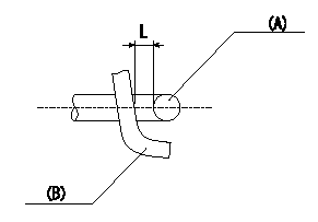
1. Adjust the actuator rod to obtain L1.
2. Apply negative pressure P1 {P2} to the actuator and confirm that it moves through its full stroke.
(A) actuator shaft
(B) Control lever
----------
L=1+1mm P1=-53.3kPa P2=-400mmHg
----------
L=1+1mm
----------
L=1+1mm P1=-53.3kPa P2=-400mmHg
----------
L=1+1mm
0000001901 V-FICD ADJUSTMENT

Adjustment of the V-FICD
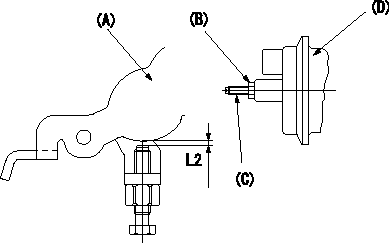
Becomes L2 when negative pressure P3 {P4} applied to the actuator.
To adjust the stroke adjust the actuator's stroke adjusting screw (C).
(A) Control lever
(B): lock nut
(C): stroke adjusting screw
(D): Actuator
----------
L2=0.56+-0.2mm P3=-53.3kPa P4=-400mmHg
----------
S=-mm L2=0.56+-0.2mm T=1.2~1.5N-m{0.12~0.15kgf-m}
----------
L2=0.56+-0.2mm P3=-53.3kPa P4=-400mmHg
----------
S=-mm L2=0.56+-0.2mm T=1.2~1.5N-m{0.12~0.15kgf-m}
0000002001 A/T PLATE ADJUSTMENT

A/T plate adjustment
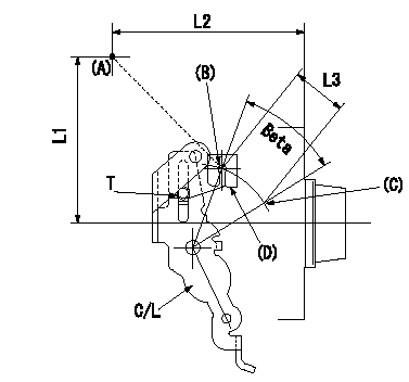
1. Turn the control lever from the idle position (B) to the Full speed position (C)
2. Adjust the A/T plate (D) so that (A)(C) - (A)(B) = L3, then fix.
----------
L3=33+-0.5mm
----------
L1=95.5mm L2=109.5mm L3=33+-0.5mm T=3.5~5N-m(0.35~0.5kgf-m)
----------
L3=33+-0.5mm
----------
L1=95.5mm L2=109.5mm L3=33+-0.5mm T=3.5~5N-m(0.35~0.5kgf-m)
Information:
start by:a) remove oil panb) remove crankshaft pulley1. Remove nuts (2) and tachometer drive cover (1). 2. Remove bolts (3) and front support (4). 3. Loosen clamp (5) and disconnect hose (6) from the timing gear cover. 4. Remove clips (8) and then disconnect three lines (7). 5. Remove clamp (9) from the water sleeve.6. Install tool (A) on the water sleeve and then push water sleeve (10) into the front cover. 7. Remove two bolts (11), connector (12) and the gasket behind it. 8. Remove bolts (13), elbow (14) and the gasket behind it. 9. Remove bolt (15) and then disconnect clamp (16) that holds the oil pump sump tube. 10. Install tooling (B) in the front cover and then fasten a hoist. Remove all the bolts that hold timing gear cover to the cylinder block. Remove the cover (17) and oil pump. The weight of the timing gear cover and oil pump is 62 kg (136 lb.).
Be extra careful not to cause damage to the crankshaft front seal during removal and installation of the timing gear cover.
Install Timing Gear Cover And Oil Pump
1. Clean the contact surfaces of the cylinder block and timing gear cover. Install the timing gear cover gasket on the cylinder block. Make sure the water sleeves are installed in the timing gear cover. Put oil on the seals on the water sleeves. 2. Install tooling (A) on timing gear cover (1).3. Put the cover in position and make an alignment of the dowels and their respective holes. Install the bolts that hold cover (1) to the cylinder block. 4. Connect clamp (3) that holds the oil pump sump tube. Install bolt (2). 5. Install gasket and elbow (4) on the timing gear cover with the bolts (5) that hold it.6. Install gasket and connector (7) in the cover and install the bolts (6) that hold it. 7. Install tool (B) on water sleeve (8), then push water sleeve into the cylinder block. 8. Install clamps (9) on the water sleeve. 9. Connect three lines (10) and install the clips (11) that hold them. 10. Install hose (13) on timing gear cover and install clamp (12). 11. Put engine support (16) in position and install the bolts (17) that hold it. 12. Put tachometer cover (15) in position and install the nuts (14) that hold it. end by:a) install crankshaft pulleyb) install oil pan