Information injection-pump assembly
ZEXEL
104740-1670
1047401670
ISUZU
8943105540
8943105540

Rating:
Cross reference number
ZEXEL
104740-1670
1047401670
ISUZU
8943105540
8943105540
Zexel num
Bosch num
Firm num
Name
Calibration Data:
Adjustment conditions
Test oil
1404 Test oil ISO4113orSAEJ967d
1404 Test oil ISO4113orSAEJ967d
Test oil temperature
degC
45
45
50
Nozzle
105000-2010
Bosch type code
NP-DN12SD12TT
Nozzle holder
105780-2080
Opening pressure
MPa
14.7
14.7
15.19
Opening pressure
kgf/cm2
150
150
155
Injection pipe
Inside diameter - outside diameter - length (mm) mm 2-6-840
Inside diameter - outside diameter - length (mm) mm 2-6-840
Transfer pump pressure
kPa
20
20
20
Transfer pump pressure
kgf/cm2
0.2
0.2
0.2
Direction of rotation (viewed from drive side)
Right R
Right R
Injection timing adjustment
Pump speed
r/min
1250
1250
1250
Boost pressure
kPa
64
62.7
65.3
Boost pressure
mmHg
480
470
490
Average injection quantity
mm3/st.
52.2
51.7
52.7
Difference in delivery
mm3/st.
4
Basic
*
Remarks
Full
Full
Injection timing adjustment_02
Pump speed
r/min
750
750
750
Boost pressure
kPa
22.85
21.7
24
Boost pressure
mmHg
170
160
180
Average injection quantity
mm3/st.
45.3
44.8
45.8
Difference in delivery
mm3/st.
3.5
Basic
*
Remarks
CBS
CBS
Injection timing adjustment_03
Pump speed
r/min
2600
2600
2600
Boost pressure
kPa
64
62.7
65.3
Boost pressure
mmHg
480
470
490
Average injection quantity
mm3/st.
15.6
14.1
17.1
Injection timing adjustment_04
Pump speed
r/min
2250
2250
2250
Boost pressure
kPa
64
62.7
65.3
Boost pressure
mmHg
480
470
490
Average injection quantity
mm3/st.
42.4
38.9
45.9
Injection timing adjustment_05
Pump speed
r/min
1250
1250
1250
Boost pressure
kPa
64
62.7
65.3
Boost pressure
mmHg
480
470
490
Average injection quantity
mm3/st.
52.2
51.2
53.2
Remarks
Full
Full
Injection timing adjustment_06
Pump speed
r/min
750
750
750
Boost pressure
kPa
22.85
21.7
24
Boost pressure
mmHg
170
160
180
Average injection quantity
mm3/st.
45.3
44.3
46.3
Remarks
CBS
CBS
Injection timing adjustment_07
Pump speed
r/min
600
600
600
Boost pressure
kPa
0
0
0
Boost pressure
mmHg
0
0
0
Average injection quantity
mm3/st.
39.7
36.2
43.2
Injection quantity adjustment
Pump speed
r/min
2600
2600
2600
Boost pressure
kPa
64
62.7
65.3
Boost pressure
mmHg
480
470
490
Average injection quantity
mm3/st.
15.6
14.6
16.6
Difference in delivery
mm3/st.
3
Basic
*
Injection quantity adjustment_02
Pump speed
r/min
2800
2800
2800
Boost pressure
kPa
64
62.7
65.3
Boost pressure
mmHg
480
470
490
Average injection quantity
mm3/st.
3
Governor adjustment
Pump speed
r/min
425
425
425
Boost pressure
kPa
0
0
0
Boost pressure
mmHg
0
0
0
Average injection quantity
mm3/st.
11.3
9.3
13.3
Difference in delivery
mm3/st.
2
Basic
*
Governor adjustment_02
Pump speed
r/min
425
425
425
Boost pressure
kPa
0
0
0
Boost pressure
mmHg
0
0
0
Average injection quantity
mm3/st.
11.3
9.3
13.3
Governor adjustment_03
Pump speed
r/min
700
700
700
Boost pressure
kPa
0
0
0
Boost pressure
mmHg
0
0
0
Average injection quantity
mm3/st.
3
Timer adjustment
Pump speed
r/min
100
100
100
Boost pressure
kPa
0
0
0
Boost pressure
mmHg
0
0
0
Average injection quantity
mm3/st.
65
55
75
Basic
*
Speed control lever angle
Pump speed
r/min
425
425
425
Boost pressure
kPa
0
0
0
Boost pressure
mmHg
0
0
0
Average injection quantity
mm3/st.
0
0
0
Remarks
Magnet OFF
Magnet OFF
0000000901
Pump speed
r/min
1250
1250
1250
Boost pressure
kPa
0
0
0
Boost pressure
mmHg
0
0
0
Overflow quantity
cm3/min
399
270
528
Stop lever angle
Pump speed
r/min
1250
1250
1250
Boost pressure
kPa
64
62.7
65.3
Boost pressure
mmHg
480
470
490
Pressure
kPa
470.5
451
490
Pressure
kgf/cm2
4.8
4.6
5
Basic
*
Stop lever angle_02
Pump speed
r/min
1250
1250
1250
Boost pressure
kPa
64
62.7
65.3
Boost pressure
mmHg
480
470
490
Pressure
kPa
470.5
451
490
Pressure
kgf/cm2
4.8
4.6
5
Stop lever angle_03
Pump speed
r/min
2100
2100
2100
Boost pressure
kPa
64
62.7
65.3
Boost pressure
mmHg
480
470
490
Pressure
kPa
676.5
647
706
Pressure
kgf/cm2
6.9
6.6
7.2
0000001101
Pump speed
r/min
1250
1250
1250
Boost pressure
kPa
64
62.7
65.3
Boost pressure
mmHg
480
470
490
Timer stroke
mm
2.7
2.5
2.9
Basic
*
_02
Pump speed
r/min
1250
1250
1250
Boost pressure
kPa
64
62.7
65.3
Boost pressure
mmHg
480
470
490
Timer stroke
mm
2.7
2.4
3
_03
Pump speed
r/min
1750
1750
1750
Boost pressure
kPa
64
62.7
65.3
Boost pressure
mmHg
480
470
490
Timer stroke
mm
4.8
4.2
5.4
_04
Pump speed
r/min
2100
2100
2100
Boost pressure
kPa
64
62.7
65.3
Boost pressure
mmHg
480
470
490
Timer stroke
mm
6.2
5.8
6.6
0000001201
Max. applied voltage
V
8
8
8
Test voltage
V
13
12
14
0000001401
Pump speed
r/min
1250
1250
1250
Boost pressure
kPa
64
62.7
65.3
Boost pressure
mmHg
480
470
490
Average injection quantity
mm3/st.
39
38.5
39.5
Timer stroke variation dT
mm
0.6
0.4
0.8
Basic
*
_02
Pump speed
r/min
1250
1250
1250
Boost pressure
kPa
64
62.7
65.3
Boost pressure
mmHg
480
470
490
Average injection quantity
mm3/st.
39
38
40
Timer stroke variation dT
mm
0.6
0.3
0.9
_03
Pump speed
r/min
1250
1250
1250
Boost pressure
kPa
64
62.7
65.3
Boost pressure
mmHg
480
470
490
Average injection quantity
mm3/st.
25
23.5
26.5
Timer stroke variation dT
mm
1.2
0.7
1.7
Timing setting
K dimension
mm
3.3
3.2
3.4
KF dimension
mm
5.8
5.7
5.9
MS dimension
mm
1.2
1.1
1.3
BCS stroke
mm
4
3.9
4.1
Control lever angle alpha
deg.
-10
-14
-6
Control lever angle beta
deg.
37
32
42
Test data Ex:
0000001801 A/T PLATE ADJUSTMENT
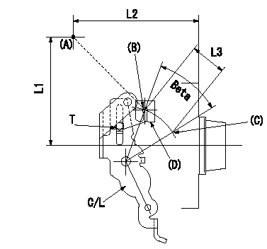
A/T plate adjustment
1. Turn the control lever from the idle position (B) to the Full speed position (C)
2. Adjust the A/T plate (D) so that (A)(C) - (A)(B) = L3, then fix.
----------
L3=33+-0.5mm
----------
L1=91.5mm L2=90.5mm L3=33+-0.5mm T=3.5~5N-m(0.35~0.5kgf-m)
----------
L3=33+-0.5mm
----------
L1=91.5mm L2=90.5mm L3=33+-0.5mm T=3.5~5N-m(0.35~0.5kgf-m)
Information:
1. Remove carbon seal dam (2) with pliers. Remove compression seal (1). 2. Install a new compression seal on the nozzle. Install a new carbon seal dam with tool (B).3. Make sure the bore in the cylinder head and the fuel inlet fittings are clean.4. Install new O-ring seals on adapter (3) and fuel injection nozzle (4).5. Install the fuel injection nozzle in the head. Turn and push the nozzle into its correct position. Never put lubricant on the nozzle or bore in the cylinder head. 6. Install the adapter in the head. Connect the nozzle and fuel injection line to the adapter. Tighten the nuts to a torque of 40 7 N m (30 5 lb.ft.).7. Install the spacer and clamp (5) that hold the nozzle to the cylinder head. end by:a) install rocker shaftsDisassemble Fuel Injection Nozzles (9N3979 & 1W5829)
start by:a) remove fuel injection nozzles Do not disassemble any nozzle until test has shown it is needed. Check each nozzle with tool (A) for leakage, the pressure, at which the nozzle opens, and the shape and amount of fuel (spray pattern) that comes out of the nozzle. Do not clean or make an adjustment to any nozzle that has a large (excessive) amount of return leakage. Excessive return leakage can be an indication of nozzle failures that cannot be corrected with an adjustment or cleaning and can cause engine damage. See TESTING 9N3979 & 1W5829 FUEL INJECTION NOZZLES in TESTING AND ADJUSTING.
Keep the work area and all tools extra clean. Be careful not to cause damage to the parts while the nozzles are disassembled and assembled.
1. Remove cap (1) from the fuel injection nozzle.2. Put the nozzle in tool (B). Put tool (B) and the nozzle in a vise. Do not put any part of a nozzle directly in a vise. Loosen locknut (2) while the lift adjustment screw is held. Turn the lift adjustment screw (3) counterclockwise one turn. Hold the lift adjustment screw (3) with a 5/64" hex wrench and remove the locknut (2).
If the lift adjustment screw is not turned counterclockwise one turn, the valve can be bent or the seat for the valve can be damaged when the pressure adjustment screw is turned.
3. Loosen the locknut (4) that holds the pressure adjustment screw. Use tool (D) to hold the pressure adjustment screw. 4. While the nozzle is held in one hand, tilt the nozzle and remove the pressure adjusting screw and locknut, spring, seat and valve. 5. If the valve does not slide out of the nozzle, install tool (C) and remove valve as follows: a) Push valve into nozzle with tool (C) until valve is against bottom of nozzle.b) Push down on body of tool (C) to engage collet on valve with tool (C). c) Turn nut counterclockwise and remove valve from the nozzle body. Put the parts in solvent to loosen carbon and deposits of foreign material. The body is assembled with an epoxy material and must