Information injection-pump assembly
ZEXEL
104740-1640
1047401640
ISUZU
8944778220
8944778220

Rating:
Cross reference number
ZEXEL
104740-1640
1047401640
ISUZU
8944778220
8944778220
Zexel num
Bosch num
Firm num
Name
Calibration Data:
Adjustment conditions
Test oil
1404 Test oil ISO4113orSAEJ967d
1404 Test oil ISO4113orSAEJ967d
Test oil temperature
degC
45
45
50
Nozzle
105000-2010
Bosch type code
NP-DN12SD12TT
Nozzle holder
105780-2080
Opening pressure
MPa
14.7
14.7
15.19
Opening pressure
kgf/cm2
150
150
155
Injection pipe
Inside diameter - outside diameter - length (mm) mm 2-6-840
Inside diameter - outside diameter - length (mm) mm 2-6-840
Transfer pump pressure
kPa
20
20
20
Transfer pump pressure
kgf/cm2
0.2
0.2
0.2
Direction of rotation (viewed from drive side)
Right R
Right R
Injection timing adjustment
Pump speed
r/min
750
750
750
Boost pressure
kPa
22.85
21.7
24
Boost pressure
mmHg
170
160
180
Average injection quantity
mm3/st.
45.3
44.8
45.8
Difference in delivery
mm3/st.
3.5
Basic
*
Remarks
CBS
CBS
Injection timing adjustment_02
Pump speed
r/min
1250
1250
1250
Boost pressure
kPa
64
62.7
65.3
Boost pressure
mmHg
480
470
490
Average injection quantity
mm3/st.
52.2
51.7
52.7
Difference in delivery
mm3/st.
4
Basic
*
Remarks
Full
Full
Injection timing adjustment_03
Pump speed
r/min
2600
2600
2600
Boost pressure
kPa
64
62.7
65.3
Boost pressure
mmHg
480
470
490
Average injection quantity
mm3/st.
15.6
14.1
17.1
Injection timing adjustment_04
Pump speed
r/min
2250
2250
2250
Boost pressure
kPa
64
62.7
65.3
Boost pressure
mmHg
480
470
490
Average injection quantity
mm3/st.
42.35
38.8
45.9
Injection timing adjustment_05
Pump speed
r/min
1250
1250
1250
Boost pressure
kPa
64
62.7
65.3
Boost pressure
mmHg
480
470
490
Average injection quantity
mm3/st.
52.2
51.2
53.2
Remarks
Full
Full
Injection timing adjustment_06
Pump speed
r/min
750
750
750
Boost pressure
kPa
22.85
21.7
24
Boost pressure
mmHg
170
160
180
Average injection quantity
mm3/st.
45.3
44.3
46.3
Remarks
CBS
CBS
Injection timing adjustment_07
Pump speed
r/min
600
600
600
Boost pressure
kPa
0
0
0
Boost pressure
mmHg
0
0
0
Average injection quantity
mm3/st.
39.75
36.2
43.3
Injection quantity adjustment
Pump speed
r/min
2600
2600
2600
Boost pressure
kPa
64
62.7
65.3
Boost pressure
mmHg
480
470
490
Average injection quantity
mm3/st.
15.6
14.6
16.6
Difference in delivery
mm3/st.
3
Basic
*
Injection quantity adjustment_02
Pump speed
r/min
2800
2800
2800
Boost pressure
kPa
64
62.7
65.3
Boost pressure
mmHg
480
470
490
Average injection quantity
mm3/st.
3.5
Governor adjustment
Pump speed
r/min
330
330
330
Boost pressure
kPa
0
0
0
Boost pressure
mmHg
0
0
0
Average injection quantity
mm3/st.
11.3
9.3
13.3
Difference in delivery
mm3/st.
2
Basic
*
Governor adjustment_02
Pump speed
r/min
330
330
330
Boost pressure
kPa
0
0
0
Boost pressure
mmHg
0
0
0
Average injection quantity
mm3/st.
11.3
9.3
13.3
Governor adjustment_03
Pump speed
r/min
400
400
400
Boost pressure
kPa
0
0
0
Boost pressure
mmHg
0
0
0
Average injection quantity
mm3/st.
3
Timer adjustment
Pump speed
r/min
100
100
100
Boost pressure
kPa
0
0
0
Boost pressure
mmHg
0
0
0
Average injection quantity
mm3/st.
65
55
75
Basic
*
Speed control lever angle
Pump speed
r/min
330
330
330
Boost pressure
kPa
0
0
0
Boost pressure
mmHg
0
0
0
Average injection quantity
mm3/st.
0
0
0
Remarks
Magnet OFF
Magnet OFF
0000000901
Pump speed
r/min
1250
1250
1250
Boost pressure
kPa
0
0
0
Boost pressure
mmHg
0
0
0
Overflow quantity
cm3/min
399
270
528
Stop lever angle
Pump speed
r/min
1250
1250
1250
Boost pressure
kPa
64
62.7
65.3
Boost pressure
mmHg
480
470
490
Pressure
kPa
470.5
451
490
Pressure
kgf/cm2
4.8
4.6
5
Basic
*
Stop lever angle_02
Pump speed
r/min
600
600
600
Boost pressure
kPa
64
62.7
65.3
Boost pressure
mmHg
480
470
490
Pressure
kPa
313.5
284
343
Pressure
kgf/cm2
3.2
2.9
3.5
Stop lever angle_03
Pump speed
r/min
1250
1250
1250
Boost pressure
kPa
64
62.7
65.3
Boost pressure
mmHg
480
470
490
Pressure
kPa
470.5
451
490
Pressure
kgf/cm2
4.8
4.6
5
Stop lever angle_04
Pump speed
r/min
2100
2100
2100
Boost pressure
kPa
64
62.7
65.3
Boost pressure
mmHg
480
470
490
Pressure
kPa
676.5
647
706
Pressure
kgf/cm2
6.9
6.6
7.2
0000001101
Pump speed
r/min
1250
1250
1250
Boost pressure
kPa
64
62.7
65.3
Boost pressure
mmHg
480
470
490
Timer stroke
mm
2.7
2.5
2.9
Basic
*
_02
Pump speed
r/min
1250
1250
1250
Boost pressure
kPa
64
62.7
65.3
Boost pressure
mmHg
480
470
490
Timer stroke
mm
2.7
2.4
3
_03
Pump speed
r/min
1750
1750
1750
Boost pressure
kPa
64
62.7
65.3
Boost pressure
mmHg
480
470
490
Timer stroke
mm
5.2
4.6
5.8
_04
Pump speed
r/min
2100
2100
2100
Boost pressure
kPa
64
62.7
65.3
Boost pressure
mmHg
480
470
490
Timer stroke
mm
6.2
5.8
6.6
0000001201
Max. applied voltage
V
8
8
8
Test voltage
V
13
12
14
0000001401
Pump speed
r/min
1250
1250
1250
Boost pressure
kPa
64
62.7
65.3
Boost pressure
mmHg
480
470
490
Average injection quantity
mm3/st.
34
33.5
34.5
Timer stroke variation dT
mm
0.6
0.4
0.8
Basic
*
_02
Pump speed
r/min
1250
1250
1250
Boost pressure
kPa
64
62.7
65.3
Boost pressure
mmHg
480
470
490
Average injection quantity
mm3/st.
34
33
35
Timer stroke variation dT
mm
0.6
0.3
0.9
_03
Pump speed
r/min
1250
1250
1250
Boost pressure
kPa
64
62.7
65.3
Boost pressure
mmHg
480
470
490
Average injection quantity
mm3/st.
20
18.5
21.5
Timer stroke variation dT
mm
1.2
0.7
1.7
Timing setting
K dimension
mm
3.3
3.2
3.4
KF dimension
mm
5.8
5.7
5.9
MS dimension
mm
1.2
1.1
1.3
BCS stroke
mm
4
3.9
4.1
Control lever angle alpha
deg.
-20.5
-24.5
-16.5
Control lever angle beta
deg.
43
38
48
Test data Ex:
0000001801 V-FICD ADJUSTMENT
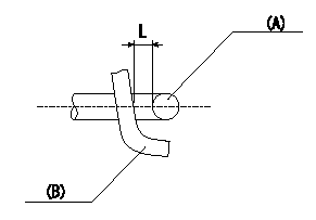
Adjustment of the V-FICD
1. Adjust the actuator rod to obtain L1.
2. Apply negative pressure P1 {P2} to the actuator and confirm that it moves through its full stroke.
(A) actuator shaft
(B) Control lever
----------
L=1+1mm P1=-53.3kPa P2=-400mmHg
----------
L=1+1mm
----------
L=1+1mm P1=-53.3kPa P2=-400mmHg
----------
L=1+1mm
0000001901 POTENTIOMETER ADJUSTMENT

Adjusting method
N = pump speed
V = output voltage
Q = injection quantity
P = boost pressure
A = adjusting point
B = target value
Vi = applied voltage
----------
----------
N1=750r/min N2=600r/min V1=2.6V V2=2.0V V3=-V Q1=31.6+-1cm3/1,000st Q2=(23.1)cm3/1,000st Q3=-cm3/1,000st P1=0kPa P2=0mmHg Vi=10V
----------
----------
N1=750r/min N2=600r/min V1=2.6V V2=2.0V V3=-V Q1=31.6+-1cm3/1,000st Q2=(23.1)cm3/1,000st Q3=-cm3/1,000st P1=0kPa P2=0mmHg Vi=10V
Information:
Before any service work is done on the fuel system, the outer surface of the injection pump housing must be clean.
Illustrations show fuel injection pump housing and governor removed from engine. Service work can be done with it installed on engine.1. Remove air bleed lines (2). 2. Remove bolts (1), flange (3), the flange assembly and the gaskets.3. Remove the bolts and the cover. 4. Remove bolts (5), solenoid (4) and the gasket.5. Remove two bolts (7) and fuel ratio control (6).6. Remove the shutoff housing from the cover. 7. Remove the bolts, lever (10) and shaft (8).8. Remove the bolts, lever (9) and shaft (11).9. Remove seal (12) from the shutoff housing. Install Shutoff Housing
1. Put 5S1454 Sealing Compound on the outside diameter of the seal and install the seal (1) with tooling (A) in the shutoff housing with the lip toward the outside. The outer face of the seal must be 1.0 mm (.039 in.) below the surface of the housing. Remove the extra sealing compound from the housing and the seal after installation. 2. Put shaft (5) in position in housing (4).3. Install lever (6) and the bolts. 4. Install shaft (2), lever (3) and the bolts. Make an alignment of the notch in shaft (2) with lever (3). 5. Put cover (7) in position on shutoff housing assembly (8) and install the bolts.6. Put fuel ratio control (10) in position and install the bolts. 7. Install the gasket, solenoid (9) and bolts on the cover.8. Put the cover in position and install the bolts.9. Install the gasket, flange assembly, gasket, flange (11) and the bolts.10. Connect air bleed lines (12).