Information injection-pump assembly
ZEXEL
104740-1601
1047401601
ISUZU
8944696831
8944696831

Rating:
Cross reference number
ZEXEL
104740-1601
1047401601
ISUZU
8944696831
8944696831
Zexel num
Bosch num
Firm num
Name
Calibration Data:
Adjustment conditions
Test oil
1404 Test oil ISO4113orSAEJ967d
1404 Test oil ISO4113orSAEJ967d
Test oil temperature
degC
45
45
50
Nozzle
105000-2010
Bosch type code
NP-DN12SD12TT
Nozzle holder
105780-2080
Opening pressure
MPa
14.7
14.7
15.19
Opening pressure
kgf/cm2
150
150
155
Injection pipe
Inside diameter - outside diameter - length (mm) mm 2-6-840
Inside diameter - outside diameter - length (mm) mm 2-6-840
Transfer pump pressure
kPa
20
20
20
Transfer pump pressure
kgf/cm2
0.2
0.2
0.2
Direction of rotation (viewed from drive side)
Right R
Right R
Injection timing adjustment
Pump speed
r/min
1250
1250
1250
Average injection quantity
mm3/st.
50.5
50
51
Difference in delivery
mm3/st.
3.5
Basic
*
Oil temperature
degC
50
48
52
Injection timing adjustment_02
Pump speed
r/min
600
600
600
Average injection quantity
mm3/st.
48.5
46.5
50.5
Oil temperature
degC
50
48
52
Injection timing adjustment_03
Pump speed
r/min
1250
1250
1250
Average injection quantity
mm3/st.
50.5
49.5
51.5
Difference in delivery
mm3/st.
3.5
Basic
*
Oil temperature
degC
50
48
52
Injection timing adjustment_04
Pump speed
r/min
2150
2150
2150
Average injection quantity
mm3/st.
40.5
38.4
42.6
Oil temperature
degC
52
50
54
Injection quantity adjustment
Pump speed
r/min
2500
2500
2500
Average injection quantity
mm3/st.
13.9
10.9
16.9
Difference in delivery
mm3/st.
4.5
Basic
*
Oil temperature
degC
55
52
58
Injection quantity adjustment_02
Pump speed
r/min
2500
2500
2500
Average injection quantity
mm3/st.
13.9
10.9
16.9
Difference in delivery
mm3/st.
4.5
Oil temperature
degC
55
52
58
Injection quantity adjustment_03
Pump speed
r/min
2850
2850
2850
Average injection quantity
mm3/st.
5
Oil temperature
degC
55
52
58
Governor adjustment
Pump speed
r/min
425
425
425
Average injection quantity
mm3/st.
10.3
8.3
12.3
Difference in delivery
mm3/st.
2
Basic
*
Oil temperature
degC
48
46
50
Governor adjustment_02
Pump speed
r/min
425
425
425
Average injection quantity
mm3/st.
10.3
8.3
12.3
Difference in delivery
mm3/st.
2
Oil temperature
degC
48
46
50
Timer adjustment
Pump speed
r/min
100
100
100
Average injection quantity
mm3/st.
50
50
70
Basic
*
Oil temperature
degC
48
46
50
Remarks
Full
Full
Timer adjustment_02
Pump speed
r/min
100
100
100
Average injection quantity
mm3/st.
50
50
70
Oil temperature
degC
48
46
50
Speed control lever angle
Pump speed
r/min
425
425
425
Average injection quantity
mm3/st.
0
0
0
Oil temperature
degC
48
46
50
Remarks
Magnet OFF at idling position
Magnet OFF at idling position
0000000901
Pump speed
r/min
1250
1250
1250
Overflow quantity
cm3/min
420
290
550
Oil temperature
degC
50
48
52
Stop lever angle
Pump speed
r/min
1250
1250
1250
Pressure
kPa
451
431
471
Pressure
kgf/cm2
4.6
4.4
4.8
Basic
*
Oil temperature
degC
50
48
52
Stop lever angle_02
Pump speed
r/min
1750
1750
1750
Pressure
kPa
588
568
608
Pressure
kgf/cm2
6
5.8
6.2
Basic
*
Oil temperature
degC
50
48
52
0000001101
Pump speed
r/min
1250
1250
1250
Timer stroke
mm
2
1.8
2.2
Basic
*
Oil temperature
degC
50
48
52
_02
Pump speed
r/min
600
600
600
Timer stroke
mm
0
0
0
Oil temperature
degC
50
48
52
_03
Pump speed
r/min
1010
1010
1010
Timer stroke
mm
0.5
0.5
Oil temperature
degC
50
48
52
_04
Pump speed
r/min
1250
1250
1250
Timer stroke
mm
2
1.6
2.4
Oil temperature
degC
50
48
52
_05
Pump speed
r/min
1750
1750
1750
Timer stroke
mm
4.2
4
4.4
Basic
*
Oil temperature
degC
50
48
52
_06
Pump speed
r/min
2150
2150
2150
Timer stroke
mm
5.9
5.4
6.4
Oil temperature
degC
52
50
54
0000001201
Max. applied voltage
V
8
8
8
Test voltage
V
13
12
14
0000001401
Pump speed
r/min
1250
1250
1250
Average injection quantity
mm3/st.
38
37.5
38.5
Timer stroke TA
mm
1.2
1.2
1.2
Timer stroke variation dT
mm
0.8
0.6
1
Basic
*
Oil temperature
degC
50
48
52
_02
Pump speed
r/min
1750
1750
1750
Average injection quantity
mm3/st.
34
33
35
Timer stroke variation dT
mm
0.8
0.5
1.1
Basic
*
Oil temperature
degC
50
48
52
_03
Pump speed
r/min
1750
1750
1750
Average injection quantity
mm3/st.
25
24
26
Timer stroke variation dT
mm
1.6
1.1
2.1
Oil temperature
degC
50
48
52
Timing setting
K dimension
mm
3.3
3.2
3.4
KF dimension
mm
5.8
5.7
5.9
MS dimension
mm
0.9
0.8
1
Control lever angle alpha
deg.
-2
-6
2
Control lever angle beta
deg.
38
33
43
Test data Ex:
0000001801 A/T PLATE ADJUSTMENT
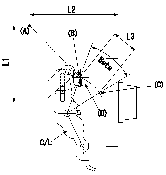
A/T plate adjustment
1. Turn (beta) so that the control lever (C/L) moves from the idle position (B) to the full speed position (C)
2. When angle beta is e, adjust A/T plate (D) so that wire stroke L3 is secured between (A) and (B), then fix.
----------
L3=33+-1mm e=38+-5deg
----------
L1=95.5mm L2=109.5mm L3=33+-1mm
----------
L3=33+-1mm e=38+-5deg
----------
L1=95.5mm L2=109.5mm L3=33+-1mm
Information:
start by:a) remove turbocharger1. Make a mark on compressor housing (1), cartridge assembly (3) and turbine housing for correct installation. 2. Loosen clamp assemblies (2). Remove compressor housing (1) and cartridge assembly (3) from the turbine housing.3. Put the cartridge assembly in tooling (A).
When nut (5) is loosened, do not put a side force on the shaft.
4. Remove nut (5) and O-ring seal (6). 5. Put the cartridge assembly in a press. Remove the shaft assembly from compressor wheel (7) and cartridge (8). 6. Remove seal ring (10) and shroud (11) from shaft assembly (9).7. Use tooling (B) to remove snap ring (12).
Do not cause damage to insert (13) when it is removed.
8. Install screwdrivers as shown. Carefully lift insert (13) out of the cartridge assembly. 9. Remove sleeve (14) and O-ring seal (15) from the insert. 10. Remove two seal rings (16) from the sleeve.11. Remove deflector (17) from the cartridge assembly. 12. Remove ring (18). 13. Remove sleeve (19) from the cartridge assembly. Make an identification of the position of bearing (20) for assembly purposes.14. Remove bearing (20) from the cartridge assembly. 15. Remove ring (21). 16. Use tooling (C) to remove snap ring (23). Remove sleeve (22) and the lower snap ring. 17. Turn the cartridge housing over. Remove snap ring (26) with tooling (C).18. Remove bearing (25), sleeve (24) and the lower snap ring. Assemble Turbocharger (Schwitzer 4TF555)
Make sure all of the oil passages in the turbocharger cartridge housing are clean and free of dirt and foreign material. Put clean engine oil on all parts of the cartridge assembly. 1. Install snap ring (4) with tooling (A) in cartridge housing (1).2. Put sleeve (3) and bearing (2) in position. Install snap ring (5) with tooling (A).3. Turn the cartridge housing over. Install snap ring (8) with tooling (A). 4. Install sleeve (6) and snap ring (7).5. Put ring (10) in position in the cartridge housing. 6. Install bearing (9) with grooved side up. Make an alignment of the dowel in the housing with the hole on the right side of the notch.7. Put sleeve (12) in position. Install ring (11). 8. Put deflector (13) in position as shown. 9. Put two seal rings (15) in position on sleeve (14).10. Put O-ring seal (17) in position on insert (16). 11. Install sleeve (14) in insert (16).12. Install insert assembly (18) with the flange down in the cartridge housing. 13. Put O-ring seal (20) in position.14. Install snap ring (19) with tooling (B). 15. Put shaft assembly (22) in tooling (D). Put 6V2055 High Vacuum Grease in the groove for seal ring (23) at assembly to one half or more of the depth of the groove all the way around the groove. 16. Put seal ring (23) in position on the shaft assembly.17. Install shround (21) on the shaft assembly (22).18. Lightly oil the wheel face that will be under the nut. Put compressor wheel (24) in position.
Do not put a side force on the shaft