Information injection-pump assembly
ZEXEL
104740-1600
1047401600
ISUZU
8944696830
8944696830

Rating:
Cross reference number
ZEXEL
104740-1600
1047401600
ISUZU
8944696830
8944696830
Zexel num
Bosch num
Firm num
Name
Calibration Data:
Adjustment conditions
Test oil
1404 Test oil ISO4113orSAEJ967d
1404 Test oil ISO4113orSAEJ967d
Test oil temperature
degC
45
45
50
Nozzle
105000-2010
Bosch type code
NP-DN12SD12TT
Nozzle holder
105780-2080
Opening pressure
MPa
14.7
14.7
15.19
Opening pressure
kgf/cm2
150
150
155
Injection pipe
Inside diameter - outside diameter - length (mm) mm 2-6-840
Inside diameter - outside diameter - length (mm) mm 2-6-840
Transfer pump pressure
kPa
20
20
20
Transfer pump pressure
kgf/cm2
0.2
0.2
0.2
Direction of rotation (viewed from drive side)
Right R
Right R
Injection timing adjustment
Pump speed
r/min
1250
1250
1250
Average injection quantity
mm3/st.
50.9
50.4
51.4
Difference in delivery
mm3/st.
3.5
Basic
*
Oil temperature
degC
50
48
52
Injection timing adjustment_02
Pump speed
r/min
600
600
600
Average injection quantity
mm3/st.
49.5
48
51
Oil temperature
degC
50
48
52
Injection timing adjustment_03
Pump speed
r/min
1250
1250
1250
Average injection quantity
mm3/st.
50.9
49.9
51.9
Difference in delivery
mm3/st.
3.5
Basic
*
Oil temperature
degC
50
48
52
Injection timing adjustment_04
Pump speed
r/min
2200
2200
2200
Average injection quantity
mm3/st.
42.7
41.1
44.3
Oil temperature
degC
52
50
54
Injection quantity adjustment
Pump speed
r/min
2500
2500
2500
Average injection quantity
mm3/st.
24.9
21.9
27.9
Difference in delivery
mm3/st.
4.5
Basic
*
Oil temperature
degC
55
52
58
Injection quantity adjustment_02
Pump speed
r/min
2500
2500
2500
Average injection quantity
mm3/st.
24.9
21.9
27.9
Difference in delivery
mm3/st.
4.5
Oil temperature
degC
55
52
58
Injection quantity adjustment_03
Pump speed
r/min
2850
2850
2850
Average injection quantity
mm3/st.
5
Oil temperature
degC
55
52
58
Governor adjustment
Pump speed
r/min
425
425
425
Average injection quantity
mm3/st.
10.3
8.3
12.3
Difference in delivery
mm3/st.
2
Basic
*
Oil temperature
degC
48
46
50
Governor adjustment_02
Pump speed
r/min
425
425
425
Average injection quantity
mm3/st.
10.3
8.3
12.3
Difference in delivery
mm3/st.
2
Oil temperature
degC
48
46
50
Timer adjustment
Pump speed
r/min
100
100
100
Average injection quantity
mm3/st.
50
50
70
Basic
*
Oil temperature
degC
48
46
50
Remarks
Full
Full
Timer adjustment_02
Pump speed
r/min
100
100
100
Average injection quantity
mm3/st.
50
50
70
Oil temperature
degC
48
46
50
Speed control lever angle
Pump speed
r/min
425
425
425
Average injection quantity
mm3/st.
0
0
0
Oil temperature
degC
48
46
50
Remarks
Magnet OFF at idling position
Magnet OFF at idling position
0000000901
Pump speed
r/min
1250
1250
1250
Overflow quantity
cm3/min
420
290
550
Oil temperature
degC
50
48
52
Stop lever angle
Pump speed
r/min
1250
1250
1250
Pressure
kPa
451
431
471
Pressure
kgf/cm2
4.6
4.4
4.8
Basic
*
Oil temperature
degC
50
48
52
Stop lever angle_02
Pump speed
r/min
1250
1250
1250
Pressure
kPa
451
431
471
Pressure
kgf/cm2
4.6
4.4
4.8
Basic
*
Oil temperature
degC
50
48
52
0000001101
Pump speed
r/min
1250
1250
1250
Timer stroke
mm
1.7
1.5
1.9
Basic
*
Oil temperature
degC
50
48
52
_02
Pump speed
r/min
930
830
1030
Timer stroke
mm
0.5
0.5
0.5
Oil temperature
degC
50
48
52
_03
Pump speed
r/min
1250
1250
1250
Timer stroke
mm
1.7
1.5
1.9
Basic
*
Oil temperature
degC
50
48
52
_04
Pump speed
r/min
2000
2000
2000
Timer stroke
mm
4.6
4.2
5
Oil temperature
degC
50
48
52
_05
Pump speed
r/min
2300
2300
2300
Timer stroke
mm
5.7
5.4
6.1
Oil temperature
degC
52
50
54
0000001201
Max. applied voltage
V
8
8
8
Test voltage
V
13
12
14
0000001401
Pump speed
r/min
1250
1250
1250
Average injection quantity
mm3/st.
28.9
28.4
29.4
Timer stroke TA
mm
1.3
1.3
1.3
Timer stroke variation dT
mm
0.4
0.2
0.6
Basic
*
Oil temperature
degC
50
48
52
_02
Pump speed
r/min
1250
1250
1250
Average injection quantity
mm3/st.
28.9
27.9
29.9
Timer stroke variation dT
mm
0.4
0.1
0.7
Basic
*
Oil temperature
degC
50
48
52
_03
Pump speed
r/min
1250
1250
1250
Average injection quantity
mm3/st.
18
17
19
Timer stroke variation dT
mm
0.8
0.3
1.3
Oil temperature
degC
50
48
52
Timing setting
K dimension
mm
3.3
3.2
3.4
KF dimension
mm
5.8
5.7
5.9
MS dimension
mm
0.9
0.8
1
Control lever angle alpha
deg.
-2
-6
2
Control lever angle beta
deg.
38
33
43
Test data Ex:
0000001801 A/T PLATE ADJUSTMENT
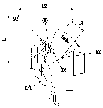
A/T plate adjustment
1. Turn (beta) so that the control lever (C/L) moves from the idle position (B) to the full speed position (C)
2. When angle beta is e, adjust A/T plate (D) so that wire stroke L3 is secured between (A) and (B), then fix.
----------
L3=33+-1mm e=(38+-5)deg
----------
L1=95.5mm L2=109.5mm L3=33+-1mm
----------
L3=33+-1mm e=(38+-5)deg
----------
L1=95.5mm L2=109.5mm L3=33+-1mm
Information:
2. Loosen clamp (5). 3. Remove three bolts (4) and elbow (6) from the turbocharger.4. Loosen clamp (7) on the inlet manifold hose. 5. Loosen clamp (8) and slide it on to the turbocharger. 6. Loosen bolts and nuts (9) and slide tubes (10) into the exhaust manifold flanges to get clearance for the removal of the turbocharger.7. Remove two bolts (12) and turbocharger (11). 8. Remove two O-ring seals (14).9. Remove three bolts (13) and mounting bracket (15). 10. Remove the two O-ring seals from the cylinder block.Install Turbocharger
1. Inspect all O-ring seals for wear or damage. Put a small amount of oil on the O-ring seals. 2. Put O-ring seals (1) and (3) in position.3. Install mounting bracket (2) and the bolts that hold it in place. 4. Put turbocharger (4) in position and install the bolts.5. Put tube (7) in position and install clamps (5). 6. Put 5P3931 Anti-Seize on the threads of bolts (6). Install bolts (6) and the nuts. 7. Put clamp (8) in position and tighten it.8. Put elbow (9) in position and install the bolts. 9. Tighten clamp (10). 10. Put hoses (12) in position and tighten clamps (11).
1. Inspect all O-ring seals for wear or damage. Put a small amount of oil on the O-ring seals. 2. Put O-ring seals (1) and (3) in position.3. Install mounting bracket (2) and the bolts that hold it in place. 4. Put turbocharger (4) in position and install the bolts.5. Put tube (7) in position and install clamps (5). 6. Put 5P3931 Anti-Seize on the threads of bolts (6). Install bolts (6) and the nuts. 7. Put clamp (8) in position and tighten it.8. Put elbow (9) in position and install the bolts. 9. Tighten clamp (10). 10. Put hoses (12) in position and tighten clamps (11).