Information injection-pump assembly
ZEXEL
104740-1591
1047401591
ISUZU
8944696821
8944696821
Rating:
Cross reference number
ZEXEL
104740-1591
1047401591
ISUZU
8944696821
8944696821
Zexel num
Bosch num
Firm num
Name
Calibration Data:
Adjustment conditions
Test oil
1404 Test oil ISO4113orSAEJ967d
1404 Test oil ISO4113orSAEJ967d
Test oil temperature
degC
45
45
50
Nozzle
105000-2010
Bosch type code
NP-DN12SD12TT
Nozzle holder
105780-2080
Opening pressure
MPa
14.7
14.7
15.19
Opening pressure
kgf/cm2
150
150
155
Injection pipe
Inside diameter - outside diameter - length (mm) mm 2-6-840
Inside diameter - outside diameter - length (mm) mm 2-6-840
Transfer pump pressure
kPa
20
20
20
Transfer pump pressure
kgf/cm2
0.2
0.2
0.2
Direction of rotation (viewed from drive side)
Right R
Right R
Injection timing adjustment
Pump speed
r/min
1250
1250
1250
Average injection quantity
mm3/st.
49.3
48.8
49.8
Difference in delivery
mm3/st.
3.5
Basic
*
Injection timing adjustment_02
Pump speed
r/min
2500
2500
2500
Average injection quantity
mm3/st.
14
10.5
17.5
Injection timing adjustment_03
Pump speed
r/min
2150
2150
2150
Average injection quantity
mm3/st.
40.7
38.2
43.2
Injection timing adjustment_04
Pump speed
r/min
1250
1250
1250
Average injection quantity
mm3/st.
49.3
48.3
50.3
Injection timing adjustment_05
Pump speed
r/min
600
600
600
Average injection quantity
mm3/st.
48.8
46.3
51.3
Injection quantity adjustment
Pump speed
r/min
2500
2500
2500
Average injection quantity
mm3/st.
14
11
17
Difference in delivery
mm3/st.
4.5
Basic
*
Injection quantity adjustment_02
Pump speed
r/min
2850
2850
2850
Average injection quantity
mm3/st.
5
Governor adjustment
Pump speed
r/min
350
350
350
Average injection quantity
mm3/st.
10.3
8.3
12.3
Difference in delivery
mm3/st.
2
Basic
*
Governor adjustment_02
Pump speed
r/min
350
350
350
Average injection quantity
mm3/st.
10.3
8.3
12.3
Governor adjustment_03
Pump speed
r/min
425
425
425
Average injection quantity
mm3/st.
3
Timer adjustment
Pump speed
r/min
100
100
100
Average injection quantity
mm3/st.
60
50
70
Basic
*
Speed control lever angle
Pump speed
r/min
350
350
350
Average injection quantity
mm3/st.
0
0
0
Remarks
Magnet OFF
Magnet OFF
0000000901
Pump speed
r/min
1250
1250
1250
Overflow quantity
cm3/min
420
288
552
Stop lever angle
Pump speed
r/min
1750
1750
1750
Pressure
kPa
588.5
569
608
Pressure
kgf/cm2
6
5.8
6.2
Basic
*
Stop lever angle_02
Pump speed
r/min
1750
1750
1750
Pressure
kPa
588.5
569
608
Pressure
kgf/cm2
6
5.8
6.2
Stop lever angle_03
Pump speed
r/min
2150
2150
2150
Pressure
kPa
666.5
637
696
Pressure
kgf/cm2
6.8
6.5
7.1
0000001101
Pump speed
r/min
1750
1750
1750
Timer stroke
mm
4.2
4
4.4
Basic
*
_02
Pump speed
r/min
1250
1250
1250
Timer stroke
mm
2
1.6
2.4
_03
Pump speed
r/min
1750
1750
1750
Timer stroke
mm
4.2
3.9
4.5
_04
Pump speed
r/min
2150
2150
2150
Timer stroke
mm
5.9
5.4
6.4
0000001201
Max. applied voltage
V
8
8
8
Test voltage
V
13
12
14
0000001401
Pump speed
r/min
1750
1750
1750
Average injection quantity
mm3/st.
34
33.5
34.5
Timer stroke variation dT
mm
0.8
0.6
1
Basic
*
_02
Pump speed
r/min
1750
1750
1750
Average injection quantity
mm3/st.
34
33
35
Timer stroke variation dT
mm
0.8
0.5
1.1
_03
Pump speed
r/min
1750
1750
1750
Average injection quantity
mm3/st.
25
23.5
26.5
Timer stroke variation dT
mm
1.6
1.1
2.1
Timing setting
K dimension
mm
3.3
3.2
3.4
KF dimension
mm
5.8
5.7
5.9
MS dimension
mm
0.9
0.8
1
Pre-stroke
mm
0.2
0.18
0.22
Control lever angle alpha
deg.
-2
-6
2
Control lever angle beta
deg.
42
37
47
Test data Ex:
0000001801 V-FICD ADJUSTMENT
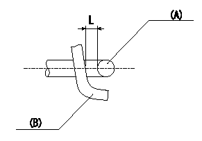
Adjustment of the V-FICD
1. Adjust the actuator rod to obtain L1.
2. Apply negative pressure P1 {P2} to the actuator and confirm that it moves through its full stroke.
(A) actuator shaft
(B) Control lever
----------
L=1+1mm P1=-53.3kPa P2=-400mmHg
----------
L=1+1mm
----------
L=1+1mm P1=-53.3kPa P2=-400mmHg
----------
L=1+1mm
Information:
1. The customer must be asked questions to determine whether his complaint is valid, or whether his diagnosis of the actual problem is correct.Some of the questions that must be asked are as follows:a. What components are vibrating?b. In what speed range does this vibration become excessive?c. Does clutch operation affect the vibration?d. What is the history of the problem?2. Run the engine through the idle speed range and note all vibrating components. Look for any loose or broken mounts, brackets and fasteners. Repair and tighten any fixtures.3. Check idle speed range with clutch disengaged. If vibrations subside, there is a balance problem with the clutch disc. The clutch disc must be repaired or replaced.4. Further analysis requires the use of a vibration instrument. Any instrument which can accurately measure the displacement of the vibration (usually in mils-inch/1000) and the frequency (cycles per minute) will be sufficient. A vibration instrument such as the IRD Mechanalysis Model 320 or an equivalent instrument can be used to analyze vibration.5. Measure vibration of cab components which have the objectionable vibration.Run engine slowly through the speed range and measure vibration with the instrument filter OUT. When peak amplitudes are found, run the engine at the speeds they occur and with the instrument filter IN, find the frequency of the vibration.If the frequency of vibration is 1/2 times of engine rpm (1/2 order), the vibration is caused by a cylinder misfiring. This must be corrected before further vibration analysis is made.If the frequency of vibration is 4 times engine rpm, no corrective action can be taken on the engine because this is the firing frequency of the 3208 Engine. The problem is in the cab or chassis resonance.If frequency is some order other than 1/2 or 4th, then further measurements must be made on the engine.6. Measurements taken on the engine must be made perpendicular to the crankshaft at the front and rear of the engine in vertical and horizontal directions.7. Record all vibrations over 4.0 mils and the engine rpm at which it occurs (100 rpm intervals are sufficient) with instrument filter OUT. Note any sudden increase and decrease in amplitudes. These occur in resonant speed ranges.If no amplitudes exceed 4.0 mils, the engine is within Caterpillar Specs.If amplitudes exceed 4.0 mils, the vibrations must be measured with the instrument filter IN to obtain the frequency of the vibrations.8. Run the engine at high idle. With the instrument filter IN, check the frequency range and record any amplitudes over 4.0 mils and the corresponding frequency. Analysis of vibrations for the possible causes is done by identifying the frequency of the vibration and where on the engine it is the greatest magnitude.9. Before vibration is rechecked, rotate the crankshaft to No. 1 cylinder top center position. Install a 3/8-16 bolt 13/4" long with a nut into the flywheel at the 9 o'clock position.10. The location on the engine at maximum vibration (front or rear) can help pinpoint the cause of the vibration.