Information injection-pump assembly
ZEXEL
104740-1590
1047401590
ISUZU
8944696820
8944696820

Rating:
Cross reference number
ZEXEL
104740-1590
1047401590
ISUZU
8944696820
8944696820
Zexel num
Bosch num
Firm num
Name
Calibration Data:
Adjustment conditions
Test oil
1404 Test oil ISO4113orSAEJ967d
1404 Test oil ISO4113orSAEJ967d
Test oil temperature
degC
45
45
50
Nozzle
105000-2010
Bosch type code
NP-DN12SD12TT
Nozzle holder
105780-2080
Opening pressure
MPa
14.7
14.7
15.19
Opening pressure
kgf/cm2
150
150
155
Injection pipe
Inside diameter - outside diameter - length (mm) mm 2-6-840
Inside diameter - outside diameter - length (mm) mm 2-6-840
Transfer pump pressure
kPa
20
20
20
Transfer pump pressure
kgf/cm2
0.2
0.2
0.2
Direction of rotation (viewed from drive side)
Right R
Right R
Injection timing adjustment
Pump speed
r/min
1250
1250
1250
Average injection quantity
mm3/st.
50.9
50.4
51.4
Difference in delivery
mm3/st.
3.5
Basic
*
Oil temperature
degC
50
48
52
Injection timing adjustment_02
Pump speed
r/min
600
600
600
Average injection quantity
mm3/st.
49.5
48
51
Oil temperature
degC
50
48
52
Injection timing adjustment_03
Pump speed
r/min
1250
1250
1250
Average injection quantity
mm3/st.
50.9
49.9
51.9
Difference in delivery
mm3/st.
3.5
Basic
*
Oil temperature
degC
50
48
52
Injection timing adjustment_04
Pump speed
r/min
2200
2200
2200
Average injection quantity
mm3/st.
42.7
41.1
44.3
Oil temperature
degC
52
50
54
Injection quantity adjustment
Pump speed
r/min
2500
2500
2500
Average injection quantity
mm3/st.
24.9
21.9
27.9
Difference in delivery
mm3/st.
4.5
Basic
*
Oil temperature
degC
55
52
58
Injection quantity adjustment_02
Pump speed
r/min
2500
2500
2500
Average injection quantity
mm3/st.
24.9
21.9
27.9
Difference in delivery
mm3/st.
4.5
Oil temperature
degC
55
52
58
Injection quantity adjustment_03
Pump speed
r/min
2850
2850
2850
Average injection quantity
mm3/st.
5
Oil temperature
degC
55
52
58
Governor adjustment
Pump speed
r/min
350
350
350
Average injection quantity
mm3/st.
10.3
8.3
12.3
Difference in delivery
mm3/st.
2
Basic
*
Oil temperature
degC
48
46
50
Governor adjustment_02
Pump speed
r/min
350
350
350
Average injection quantity
mm3/st.
10.3
8.3
12.3
Difference in delivery
mm3/st.
2
Oil temperature
degC
48
46
50
Timer adjustment
Pump speed
r/min
100
100
100
Average injection quantity
mm3/st.
50
50
70
Oil temperature
degC
48
46
50
Remarks
Full
Full
Timer adjustment_02
Pump speed
r/min
100
100
100
Average injection quantity
mm3/st.
50
50
70
Oil temperature
degC
48
46
50
Speed control lever angle
Pump speed
r/min
350
350
350
Average injection quantity
mm3/st.
0
0
0
Oil temperature
degC
48
46
50
Remarks
Magnet OFF at idling position
Magnet OFF at idling position
0000000901
Pump speed
r/min
1250
1250
1250
Overflow quantity
cm3/min
420
290
550
Oil temperature
degC
50
48
52
Stop lever angle
Pump speed
r/min
1250
1250
1250
Pressure
kPa
451
431
471
Pressure
kgf/cm2
4.6
4.4
4.8
Basic
*
Oil temperature
degC
50
48
52
Stop lever angle_02
Pump speed
r/min
1250
1250
1250
Pressure
kPa
451
431
471
Pressure
kgf/cm2
4.6
4.4
4.8
Basic
*
Oil temperature
degC
50
48
52
0000001101
Pump speed
r/min
1250
1250
1250
Timer stroke
mm
1.7
1.5
1.9
Basic
*
Oil temperature
degC
50
48
52
_02
Pump speed
r/min
930
830
1030
Timer stroke
mm
0.5
0.5
0.5
Oil temperature
degC
50
48
52
_03
Pump speed
r/min
1250
1250
1250
Timer stroke
mm
1.7
1.5
1.9
Basic
*
Oil temperature
degC
50
48
52
_04
Pump speed
r/min
2000
2000
2000
Timer stroke
mm
4.6
4.2
5
Oil temperature
degC
50
48
52
_05
Pump speed
r/min
2300
2300
2300
Timer stroke
mm
5.7
5.4
6.1
Oil temperature
degC
52
50
54
0000001201
Max. applied voltage
V
8
8
8
Test voltage
V
13
12
14
0000001401
Pump speed
r/min
1250
1250
1250
Average injection quantity
mm3/st.
28.9
28.4
29.4
Timer stroke TA
mm
1.3
1.3
1.3
Timer stroke variation dT
mm
0.4
0.2
0.6
Basic
*
Oil temperature
degC
50
48
52
_02
Pump speed
r/min
1250
1250
1250
Average injection quantity
mm3/st.
28.9
27.9
29.9
Timer stroke variation dT
mm
0.4
0.1
0.7
Basic
*
Oil temperature
degC
50
48
52
_03
Pump speed
r/min
1250
1250
1250
Average injection quantity
mm3/st.
18
17
19
Timer stroke variation dT
mm
0.8
0.3
1.3
Oil temperature
degC
50
48
52
Timing setting
K dimension
mm
3.3
3.2
3.4
KF dimension
mm
5.8
5.7
5.9
MS dimension
mm
0.9
0.8
1
Control lever angle alpha
deg.
-2
-6
2
Control lever angle beta
deg.
42
37
47
Test data Ex:
0000001801 V-FICD ADJUSTMENT
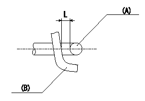
Adjustment of the V-FICD
1. Adjust the actuator rod to obtain L1.
2. Apply negative pressure P1 {P2} to the actuator and confirm that it moves through its full stroke.
(A) actuator shaft
(B) Control lever
----------
L=1+1mm P1=-53.3kPa P2=-400mmHg
----------
L=1+1mm
----------
L=1+1mm P1=-53.3kPa P2=-400mmHg
----------
L=1+1mm
Information:
Recommended Procedure
A. Outside Leaks1. Leaks in Hoses or Connections ... Check all hoses and connections for visual signs of leakage. If no leaks are seen, look for damage to hoses or loose clamps.2. Leaks in the Radiator and/or Expansion Tank ... Put pressure to the radiator and/or expansion tank with the 9S8140 Cooling System Pressurizing Pump Group and check for leaks.3. Leaks in the Heater ... Put pressure to the cooling system with the 9S8140 Cooling System pressurizing Pump Group and check the heater for leaks.4. Leaks in the Water Pump ... Check the water pump for leaks before starting the engine, then start the engine and look for leaks. If there are leaks at the water pump, repair or install a new water pump.5. Cylinder Head Gasket Leakage ... Look for leaks along the surface of the cylinder head gasket. If you see leaks, install a new head gasket.B. Coolant Leaks at the Overflow Tube6. Bad Pressure Cap or Relief Valve ... Check the sealing surfaces of the pressure cap and the radiator to be sure the cap is sealing correctly. Check the opening pressure and sealing ability of the pressure cap or relief valve with the 9S8140 Cooling System Pressurizing Pump Group.7. Engine Runs Too Hot ... If coolant temperature is too high, pressure will be high enough to move the cap off of the sealing surface in the radiator and cause coolant loss through the overflow tube. See "Above Normal Heating" in COOLING SYSTEM Chart.8. Expansion Tank Too Small or Installed Wrong ... The expansion tank can be either a part of the radiator or it can be installed separately from the radiator. The expansion tank must be large enough to hold the expansion of the coolant as it gets warm or has sudden changes in pressure. Make sure the expansion tank is installed correctly, and the size is according to the recommendations of the Truck Manufacturer.9. Cylinder Head Gasket Leakage, or Crack(s) in Cylinder Head or Cylinder Block ... Remove the radiator cap and with the engine running look for air bubbles in the coolant. Bubbles in the coolant are a sign of probable leakage at the head gasket. With the engine not running, check each cylinder with the cylinder leakage tester. Special Instruction, Form No. GMG00694 gives the test procedure. If you see air bubbles in the coolant during this test, there is a leak of combustion gas into the cooling system. Remove the cylinder heads from the engine. Check cylinder heads, cylinder walls and head gasket surface of the cylinder block for cracks. When installing heads, use new head gasket.C. Inside Leakage10. Cylinder Head Gasket Leakage ... If the cylinder head gasket leaks between a water passage and an opening into the crankcase, coolant will get into the crankcase.11. Crack(s) in Cylinder Head ... Crack(s) in the upper surface of the cylinder head, or an area between a water passage and an opening into the crankcase, can allow
A. Outside Leaks1. Leaks in Hoses or Connections ... Check all hoses and connections for visual signs of leakage. If no leaks are seen, look for damage to hoses or loose clamps.2. Leaks in the Radiator and/or Expansion Tank ... Put pressure to the radiator and/or expansion tank with the 9S8140 Cooling System Pressurizing Pump Group and check for leaks.3. Leaks in the Heater ... Put pressure to the cooling system with the 9S8140 Cooling System pressurizing Pump Group and check the heater for leaks.4. Leaks in the Water Pump ... Check the water pump for leaks before starting the engine, then start the engine and look for leaks. If there are leaks at the water pump, repair or install a new water pump.5. Cylinder Head Gasket Leakage ... Look for leaks along the surface of the cylinder head gasket. If you see leaks, install a new head gasket.B. Coolant Leaks at the Overflow Tube6. Bad Pressure Cap or Relief Valve ... Check the sealing surfaces of the pressure cap and the radiator to be sure the cap is sealing correctly. Check the opening pressure and sealing ability of the pressure cap or relief valve with the 9S8140 Cooling System Pressurizing Pump Group.7. Engine Runs Too Hot ... If coolant temperature is too high, pressure will be high enough to move the cap off of the sealing surface in the radiator and cause coolant loss through the overflow tube. See "Above Normal Heating" in COOLING SYSTEM Chart.8. Expansion Tank Too Small or Installed Wrong ... The expansion tank can be either a part of the radiator or it can be installed separately from the radiator. The expansion tank must be large enough to hold the expansion of the coolant as it gets warm or has sudden changes in pressure. Make sure the expansion tank is installed correctly, and the size is according to the recommendations of the Truck Manufacturer.9. Cylinder Head Gasket Leakage, or Crack(s) in Cylinder Head or Cylinder Block ... Remove the radiator cap and with the engine running look for air bubbles in the coolant. Bubbles in the coolant are a sign of probable leakage at the head gasket. With the engine not running, check each cylinder with the cylinder leakage tester. Special Instruction, Form No. GMG00694 gives the test procedure. If you see air bubbles in the coolant during this test, there is a leak of combustion gas into the cooling system. Remove the cylinder heads from the engine. Check cylinder heads, cylinder walls and head gasket surface of the cylinder block for cracks. When installing heads, use new head gasket.C. Inside Leakage10. Cylinder Head Gasket Leakage ... If the cylinder head gasket leaks between a water passage and an opening into the crankcase, coolant will get into the crankcase.11. Crack(s) in Cylinder Head ... Crack(s) in the upper surface of the cylinder head, or an area between a water passage and an opening into the crankcase, can allow