Information injection-pump assembly
ZEXEL
104740-1422
1047401422
ISUZU
8944542982
8944542982
Rating:
Cross reference number
ZEXEL
104740-1422
1047401422
ISUZU
8944542982
8944542982
Zexel num
Bosch num
Firm num
Name
Calibration Data:
Adjustment conditions
Test oil
1404 Test oil ISO4113orSAEJ967d
1404 Test oil ISO4113orSAEJ967d
Test oil temperature
degC
45
45
50
Nozzle
105000-2010
Bosch type code
NP-DN12SD12TT
Nozzle holder
105780-2080
Opening pressure
MPa
14.7
14.7
15.19
Opening pressure
kgf/cm2
150
150
155
Injection pipe
Inside diameter - outside diameter - length (mm) mm 2-6-840
Inside diameter - outside diameter - length (mm) mm 2-6-840
Transfer pump pressure
kPa
20
20
20
Transfer pump pressure
kgf/cm2
0.2
0.2
0.2
Direction of rotation (viewed from drive side)
Right R
Right R
Injection timing adjustment
Pump speed
r/min
900
900
900
Boost pressure
kPa
33.3
32
34.6
Boost pressure
mmHg
250
240
260
Average injection quantity
mm3/st.
43.5
43
44
Difference in delivery
mm3/st.
3.5
Basic
*
Oil temperature
degC
50
48
52
Remarks
CBS
CBS
Injection timing adjustment_02
Pump speed
r/min
1250
1250
1250
Boost pressure
kPa
80
78.7
81.3
Boost pressure
mmHg
600
590
610
Average injection quantity
mm3/st.
46.6
46.1
47.1
Difference in delivery
mm3/st.
4
Basic
*
Oil temperature
degC
50
48
52
Remarks
Full
Full
Injection timing adjustment_03
Pump speed
r/min
900
900
900
Boost pressure
kPa
33.3
32
34.6
Boost pressure
mmHg
250
240
260
Average injection quantity
mm3/st.
43.5
42.5
44.5
Difference in delivery
mm3/st.
3.5
Basic
*
Oil temperature
degC
50
48
52
Injection timing adjustment_04
Pump speed
r/min
1150
1150
1150
Boost pressure
kPa
80
78.7
81.3
Boost pressure
mmHg
600
590
610
Average injection quantity
mm3/st.
47.5
45.5
49.5
Oil temperature
degC
50
48
52
Injection timing adjustment_05
Pump speed
r/min
1250
1250
1250
Boost pressure
kPa
80
78.7
81.3
Boost pressure
mmHg
600
590
610
Average injection quantity
mm3/st.
46.6
45.6
47.6
Difference in delivery
mm3/st.
4
Basic
*
Oil temperature
degC
50
48
52
Injection timing adjustment_06
Pump speed
r/min
2000
2000
2000
Boost pressure
kPa
80
78.7
81.3
Boost pressure
mmHg
600
590
610
Average injection quantity
mm3/st.
42.6
40.6
44.6
Oil temperature
degC
50
48
52
Injection timing adjustment_07
Pump speed
r/min
2150
2150
2150
Boost pressure
kPa
80
78.7
81.3
Boost pressure
mmHg
600
590
610
Average injection quantity
mm3/st.
39.8
36.8
42.8
Oil temperature
degC
52
50
54
Injection timing adjustment_08
Pump speed
r/min
2300
2300
2300
Boost pressure
kPa
80
78.7
81.3
Boost pressure
mmHg
600
590
610
Average injection quantity
mm3/st.
33.8
30.8
36.8
Oil temperature
degC
52
50
54
Injection timing adjustment_09
Pump speed
r/min
1250
1250
1250
Boost pressure
kPa
0
0
0
Boost pressure
mmHg
0
0
0
Average injection quantity
mm3/st.
40.4
38.4
42.4
Oil temperature
degC
50
48
52
Injection quantity adjustment
Pump speed
r/min
2300
2300
2300
Boost pressure
kPa
80
78.7
81.3
Boost pressure
mmHg
600
590
610
Average injection quantity
mm3/st.
33.8
30.8
36.8
Basic
*
Oil temperature
degC
52
50
54
Injection quantity adjustment_02
Pump speed
r/min
2550
2550
2550
Boost pressure
kPa
80
78.7
81.3
Boost pressure
mmHg
600
590
610
Average injection quantity
mm3/st.
22.8
22.8
22.8
Difference in delivery
mm3/st.
7
Oil temperature
degC
55
52
58
Injection quantity adjustment_03
Pump speed
r/min
2900
2900
2900
Boost pressure
kPa
80
78.7
81.3
Boost pressure
mmHg
600
590
610
Average injection quantity
mm3/st.
7
Oil temperature
degC
55
52
58
Governor adjustment
Pump speed
r/min
375
375
375
Boost pressure
kPa
0
0
0
Boost pressure
mmHg
0
0
0
Average injection quantity
mm3/st.
11.3
9.3
13.3
Difference in delivery
mm3/st.
2
Basic
*
Oil temperature
degC
48
46
50
Governor adjustment_02
Pump speed
r/min
375
375
375
Boost pressure
kPa
0
0
0
Boost pressure
mmHg
0
0
0
Average injection quantity
mm3/st.
11.3
9.3
13.3
Difference in delivery
mm3/st.
2
Oil temperature
degC
48
46
50
Timer adjustment
Pump speed
r/min
100
100
100
Boost pressure
kPa
0
0
0
Boost pressure
mmHg
0
0
0
Average injection quantity
mm3/st.
60
60
Basic
*
Oil temperature
degC
48
46
50
Remarks
Full
Full
Timer adjustment_02
Pump speed
r/min
100
100
100
Boost pressure
kPa
0
0
0
Boost pressure
mmHg
0
0
0
Average injection quantity
mm3/st.
60
60
Oil temperature
degC
48
46
50
Speed control lever angle
Pump speed
r/min
375
375
375
Boost pressure
kPa
0
0
0
Boost pressure
mmHg
0
0
0
Average injection quantity
mm3/st.
0
0
0
Oil temperature
degC
48
46
50
Remarks
Magnet OFF at idling position
Magnet OFF at idling position
0000000901
Pump speed
r/min
1250
1250
1250
Boost pressure
kPa
0
0
0
Boost pressure
mmHg
0
0
0
Overflow quantity
cm3/min
400
270
530
Oil temperature
degC
50
48
52
Stop lever angle
Pump speed
r/min
1250
1250
1250
Boost pressure
kPa
0
0
0
Boost pressure
mmHg
0
0
0
Pressure
kPa
471
451
491
Pressure
kgf/cm2
4.8
4.6
5
Basic
*
Oil temperature
degC
50
48
52
Stop lever angle_02
Pump speed
r/min
1250
1250
1250
Boost pressure
kPa
0
0
0
Boost pressure
mmHg
0
0
0
Pressure
kPa
471
451
491
Pressure
kgf/cm2
4.8
4.6
5
Basic
*
Oil temperature
degC
50
48
52
0000001101
Pump speed
r/min
1250
1250
1250
Boost pressure
kPa
0
0
0
Boost pressure
mmHg
0
0
0
Timer stroke
mm
3.4
3.2
3.6
Basic
*
Oil temperature
degC
50
48
52
_02
Pump speed
r/min
860
760
960
Boost pressure
kPa
0
0
0
Boost pressure
mmHg
0
0
0
Timer stroke
mm
0.5
0.5
0.5
Oil temperature
degC
50
48
52
_03
Pump speed
r/min
1250
1250
1250
Boost pressure
kPa
0
0
0
Boost pressure
mmHg
0
0
0
Timer stroke
mm
3.4
3.2
3.6
Basic
*
Oil temperature
degC
50
48
52
_04
Pump speed
r/min
1700
1700
1700
Boost pressure
kPa
0
0
0
Boost pressure
mmHg
0
0
0
Timer stroke
mm
6.8
6.4
7.2
Oil temperature
degC
50
48
52
_05
Pump speed
r/min
2150
2150
2150
Boost pressure
kPa
0
0
0
Boost pressure
mmHg
0
0
0
Timer stroke
mm
9
8.7
9.4
Oil temperature
degC
52
50
54
_06
Pump speed
r/min
0
0
0
Boost pressure
kPa
0
0
0
Boost pressure
mmHg
0
0
0
Timer stroke
mm
2.5
2.3
2.7
Oil temperature
degC
48
46
50
Remarks
C.S.D. advance angle
C.S.D. advance angle
_07
Pump speed
r/min
600
500
700
Boost pressure
kPa
0
0
0
Boost pressure
mmHg
0
0
0
Oil temperature
degC
50
48
52
Remarks
C.D.. cancel speed.
C.D.. cancel speed.
0000001201
Max. applied voltage
V
8
8
8
Test voltage
V
13
12
14
Timing setting
K dimension
mm
3.3
3.2
3.4
KF dimension
mm
5.8
5.7
5.9
MS dimension
mm
1.3
1.2
1.4
BCS stroke
mm
1.9
1.7
2.1
Control lever angle alpha
deg.
17
13
21
Control lever angle beta
deg.
42
37
47
Test data Ex:
0000001801 V-FICD ADJUSTMENT
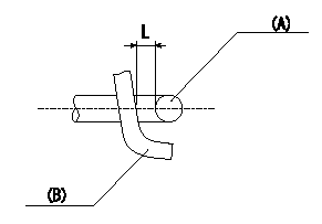
Adjustment of the V-FICD
1. Adjust the actuator rod to obtain L1.
2. Apply negative pressure P1 {P2} to the actuator and confirm that it moves through its full stroke.
(A) actuator shaft
(B) Control lever
----------
L=1+1mm P1=-53.3kPa P2=-400mmHg
----------
L=1+1mm
----------
L=1+1mm P1=-53.3kPa P2=-400mmHg
----------
L=1+1mm
0000001901 POTENTIOMETER ADJUSTMENT
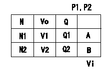
Potentiometer adjustment (oval)
Adjust at boost pressure P1 (P2).
1. At pump speed N1 and injection quantity Q1, determine the control lever position at output voltage V1. Then, hold the dummy bolt against the lever and fix.
2. In the fixed position, install the potentiometer so that the output voltage is V2.
3. After completing potentiometer installation, remove the dummy bolt.
P:Boost pressure
N:Pump speed
Vo:Output voltage
Q:Injection quantity
A:Adjusting point
Vi:Applied voltage
----------
P1=80.0(kPa) P2=600(mmHg) N1=700(r/min) Q1=25.4+-1(mm3/st) V1=4.10(V) V2=3.33(V) Vi=10(V)
----------
P1=80.0(kPa) P2=600(mmHg) N1=700(r/min) N2=500(r/min) V1=4.10(V) V2=3.33(V) Q1=25.4+-1(mm3/st) Q2=22.7(mm3/st) Vi=10(V)
----------
P1=80.0(kPa) P2=600(mmHg) N1=700(r/min) Q1=25.4+-1(mm3/st) V1=4.10(V) V2=3.33(V) Vi=10(V)
----------
P1=80.0(kPa) P2=600(mmHg) N1=700(r/min) N2=500(r/min) V1=4.10(V) V2=3.33(V) Q1=25.4+-1(mm3/st) Q2=22.7(mm3/st) Vi=10(V)
Information:
3. Remove the connecting rod caps (1) from these pistons, and push the pistons upward until the rings clear the cylinder liner. 4. Remove the two pistons.5. Repeat Step 2 through 4 for the remaining pistons.Install Pistons
1. Thoroughly lubricate the crankshaft bearing journals and cylinder liners with clean SAE 30 engine oil.2. Lubricate the piston rings and connecting rod bearings with clean SAE 30 engine oil. 3. Using compressor (A), install the pistons with "V" mark on piston aligned with "V" mark on cylinder block. Guide the lower end of the rod over the crankshaft journal to prevent damage to the crankshaft.4. Lubricate the threads of cap retaining bolts with clean SAE 30 engine oil.5. Position the caps on the connecting rods, and install retaining nuts. Tighten nuts initially to 30 3 lb. ft. (4,1 0,4 mkg). Mark the nut and end of bolt, and tighten nut an additional 90° from mark.
When installing connecting rod cap, be sure that the number marked on side of cap is adjacent to and corresponds to the number marked on side of connecting rod.
6. Rotate the crankshaft until the next two bearing journals are at bottom dead center.7. Repeat Steps 2 through 5 for the remaining two pistons.concluding steps: a) install oil pumpb) install cylinder head assemblyDisassemble Pistons
preparatory step: a) remove pistons 1. Remove piston pin retaining rings (2).2. Remove piston pin (1) and remove piston from the connecting rod. 3. Remove the piston rings using ring expander (A).Assemble Pistons
1. Using ring expander (A), install the piston rings. The two compression rings are marked "UP - 1" and "UP - 2". The rings must be installed with these marks toward the top of the piston with "UP - 1" being the top ring. After all three rings have been installed on piston, stagger the ring caps 120° apart.2. Lubricate the piston pin with clean SAE 30 engine oil. 3. Position the piston on the connecting rod with the "V" mark (2) on the piston and number (1) on the connecting rod on the same side.4. Install the piston pin retaining rings. Make certain the retaining rings are seated in their grooves.concluding step: a) install pistons