Information injection-pump assembly
ZEXEL
104740-1421
1047401421
ISUZU
8944542981
8944542981
Rating:
Cross reference number
ZEXEL
104740-1421
1047401421
ISUZU
8944542981
8944542981
Zexel num
Bosch num
Firm num
Name
Calibration Data:
Adjustment conditions
Test oil
1404 Test oil ISO4113orSAEJ967d
1404 Test oil ISO4113orSAEJ967d
Test oil temperature
degC
45
45
50
Nozzle
105000-2010
Bosch type code
NP-DN12SD12TT
Nozzle holder
105780-2080
Opening pressure
MPa
14.7
14.7
15.19
Opening pressure
kgf/cm2
150
150
155
Injection pipe
Inside diameter - outside diameter - length (mm) mm 2-6-840
Inside diameter - outside diameter - length (mm) mm 2-6-840
Transfer pump pressure
kPa
20
20
20
Transfer pump pressure
kgf/cm2
0.2
0.2
0.2
Direction of rotation (viewed from drive side)
Right R
Right R
Injection timing adjustment
Pump speed
r/min
900
900
900
Boost pressure
kPa
26.7
25.4
28
Boost pressure
mmHg
200
190
210
Average injection quantity
mm3/st.
43.5
43
44
Difference in delivery
mm3/st.
3.5
Basic
*
Oil temperature
degC
50
48
52
Remarks
CBS
CBS
Injection timing adjustment_02
Pump speed
r/min
1250
1250
1250
Boost pressure
kPa
80
78.7
81.3
Boost pressure
mmHg
600
590
610
Average injection quantity
mm3/st.
47.8
47.3
48.3
Difference in delivery
mm3/st.
4
Basic
*
Oil temperature
degC
50
48
52
Remarks
Full
Full
Injection timing adjustment_03
Pump speed
r/min
900
900
900
Boost pressure
kPa
26.7
25.4
28
Boost pressure
mmHg
200
190
210
Average injection quantity
mm3/st.
43.5
42.5
44.5
Difference in delivery
mm3/st.
3.5
Basic
*
Oil temperature
degC
50
48
52
Injection timing adjustment_04
Pump speed
r/min
1250
1250
1250
Boost pressure
kPa
80
78.7
81.3
Boost pressure
mmHg
600
590
610
Average injection quantity
mm3/st.
47.8
46.8
48.8
Difference in delivery
mm3/st.
4
Basic
*
Oil temperature
degC
50
48
52
Injection timing adjustment_05
Pump speed
r/min
2175
2175
2175
Boost pressure
kPa
80
78.7
81.3
Boost pressure
mmHg
600
590
610
Average injection quantity
mm3/st.
42.9
40.9
44.9
Oil temperature
degC
52
50
54
Injection timing adjustment_06
Pump speed
r/min
1250
1250
1250
Boost pressure
kPa
0
0
0
Boost pressure
mmHg
0
0
0
Average injection quantity
mm3/st.
41.4
39.4
43.4
Oil temperature
degC
50
48
52
Injection quantity adjustment
Pump speed
r/min
2550
2550
2550
Boost pressure
kPa
80
78.7
81.3
Boost pressure
mmHg
600
590
610
Average injection quantity
mm3/st.
22.8
19.8
25.8
Difference in delivery
mm3/st.
7
Basic
*
Oil temperature
degC
55
53
57
Injection quantity adjustment_02
Pump speed
r/min
2550
2550
2550
Boost pressure
kPa
80
78.7
81.3
Boost pressure
mmHg
600
590
610
Average injection quantity
mm3/st.
22.8
19.8
25.8
Difference in delivery
mm3/st.
7
Oil temperature
degC
55
52
58
Injection quantity adjustment_03
Pump speed
r/min
2800
2800
2800
Boost pressure
kPa
80
78.7
81.3
Boost pressure
mmHg
600
590
610
Average injection quantity
mm3/st.
7
Oil temperature
degC
55
53
57
Governor adjustment
Pump speed
r/min
375
375
375
Boost pressure
kPa
0
0
0
Boost pressure
mmHg
0
0
0
Average injection quantity
mm3/st.
11.3
9.3
13.3
Difference in delivery
mm3/st.
2
Basic
*
Oil temperature
degC
48
46
50
Governor adjustment_02
Pump speed
r/min
375
375
375
Boost pressure
kPa
0
0
0
Boost pressure
mmHg
0
0
0
Average injection quantity
mm3/st.
11.3
9.3
13.3
Difference in delivery
mm3/st.
2
Oil temperature
degC
48
46
50
Timer adjustment
Pump speed
r/min
100
100
100
Boost pressure
kPa
0
0
0
Boost pressure
mmHg
0
0
0
Average injection quantity
mm3/st.
60
60
Basic
*
Oil temperature
degC
48
46
50
Remarks
Full
Full
Timer adjustment_02
Pump speed
r/min
100
100
100
Boost pressure
kPa
0
0
0
Boost pressure
mmHg
0
0
0
Average injection quantity
mm3/st.
60
60
Oil temperature
degC
48
46
50
Speed control lever angle
Pump speed
r/min
375
375
375
Boost pressure
kPa
0
0
0
Boost pressure
mmHg
0
0
0
Average injection quantity
mm3/st.
0
0
0
Oil temperature
degC
48
46
50
Remarks
Magnet OFF at idling position
Magnet OFF at idling position
0000000901
Pump speed
r/min
1250
1250
1250
Boost pressure
kPa
0
0
0
Boost pressure
mmHg
0
0
0
Overflow quantity
cm3/min
400
270
530
Oil temperature
degC
50
48
52
Stop lever angle
Pump speed
r/min
1250
1250
1250
Boost pressure
kPa
0
0
0
Boost pressure
mmHg
0
0
0
Pressure
kPa
471
451
491
Pressure
kgf/cm2
4.8
4.6
5
Basic
*
Oil temperature
degC
50
48
52
Stop lever angle_02
Pump speed
r/min
1250
1250
1250
Boost pressure
kPa
0
0
0
Boost pressure
mmHg
0
0
0
Pressure
kPa
471
451
491
Pressure
kgf/cm2
4.8
4.6
5
Basic
*
Oil temperature
degC
50
48
52
Stop lever angle_03
Pump speed
r/min
2175
2175
2175
Boost pressure
kPa
0
0
0
Boost pressure
mmHg
0
0
0
Pressure
kPa
686
657
715
Pressure
kgf/cm2
7
6.7
7.3
Oil temperature
degC
52
50
54
0000001101
Pump speed
r/min
1250
1250
1250
Boost pressure
kPa
0
0
0
Boost pressure
mmHg
0
0
0
Timer stroke
mm
3.4
3.2
3.6
Basic
*
Oil temperature
degC
50
48
52
_02
Pump speed
r/min
860
760
960
Boost pressure
kPa
0
0
0
Boost pressure
mmHg
0
0
0
Timer stroke
mm
0.5
0.5
0.5
Oil temperature
degC
50
48
52
_03
Pump speed
r/min
1250
1250
1250
Boost pressure
kPa
0
0
0
Boost pressure
mmHg
0
0
0
Timer stroke
mm
3.4
3.2
3.6
Basic
*
Oil temperature
degC
50
48
52
_04
Pump speed
r/min
1700
1700
1700
Boost pressure
kPa
0
0
0
Boost pressure
mmHg
0
0
0
Timer stroke
mm
6.8
6.5
7.1
Oil temperature
degC
50
48
52
_05
Pump speed
r/min
2175
2175
2175
Boost pressure
kPa
0
0
0
Boost pressure
mmHg
0
0
0
Timer stroke
mm
9
8.7
9.4
Oil temperature
degC
52
50
54
_06
Pump speed
r/min
0
0
0
Boost pressure
kPa
0
0
0
Boost pressure
mmHg
0
0
0
Timer stroke
mm
2.5
2.3
2.7
Oil temperature
degC
48
46
50
Remarks
C.S.D. advance angle
C.S.D. advance angle
_07
Pump speed
r/min
600
500
700
Boost pressure
kPa
0
0
0
Boost pressure
mmHg
0
0
0
Oil temperature
degC
50
48
52
Remarks
C.D.. cancel speed.
C.D.. cancel speed.
0000001201
Max. applied voltage
V
8
8
8
Test voltage
V
13
12
14
Timing setting
K dimension
mm
3.3
3.2
3.4
KF dimension
mm
5.8
5.7
5.9
MS dimension
mm
1.4
1.3
1.5
BCS stroke
mm
1.8
1.6
2
Control lever angle alpha
deg.
17
13
21
Control lever angle beta
deg.
42
37
47
Test data Ex:
0000001801 V-FICD ADJUSTMENT
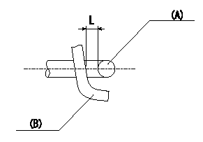
Adjustment of the V-FICD
1. Adjust the actuator rod to obtain L1.
2. Apply negative pressure P1 {P2} to the actuator and confirm that it moves through its full stroke.
(A) actuator shaft
(B) Control lever
----------
L=1+1mm P1=-53.3kPa P2=-400mmHg
----------
L=1+1mm
----------
L=1+1mm P1=-53.3kPa P2=-400mmHg
----------
L=1+1mm
0000001901 POTENTIOMETER ADJUSTMENT
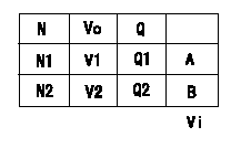
Potentiometer adjustment (oval)
N:Pump speed
Vo:Output voltage
Q:Injection quantity
A:Adjusting point
B:Target value
Vi:Applied voltage
----------
----------
N1=700(r/min) N2=500(r/min) V1=4.10(V) V2=3.33(V) Q1=22.9+-1(mm3/st) Q2=(18.6(mm3/st)) Vi=10(V)
----------
----------
N1=700(r/min) N2=500(r/min) V1=4.10(V) V2=3.33(V) Q1=22.9+-1(mm3/st) Q2=(18.6(mm3/st)) Vi=10(V)
Information:
1. Disconnect the fuel ratio control sensing line (1). Remove the sensing line clamp bolt (2).2. Disconnect the air compressor water return line (6). 3. Remove the cylinder head air inlet line (3).4. Remove the retaining bolts (4) and the fan drive mounting bracket (5).5. Remove the cylinder head retaining bolts. Attach a hoist and remove the cylinder head assembly - weight 164 lbs. (74,4 kg).Install Cylinder Head
1. Thoroughly clean the sealing surfaces of the cylinder head and cylinder block. Position a new head gasket on the engine and install the cylinder head.2. Install the push rods and rocker shaft assembly.3. Coat the threads of the cylinder head retaining bolts with 4S9416 Anti-Seize Compound. Install bolts and washers, and tighten them in the following sequence: 1 - Tighten all numbered bolts in numerical order to 115 lb. ft. (15,9 mkg).2 - Retighten all numbered bolts in numerical order to 175 5 lb. ft. (24,2 0,7 mkg).3 - Finally, retighten all numbered bolts (hand torque only) in numerical order to 175 5 lb. ft. (24,2 0,7 mkg).4 - Tighten all lettered bolts in alphabetical order to 22 lb. ft. (3,0 mkg).5 - Retighten all lettered bolts in alphabetical order to 32 5 lb. ft. (4,4 0,7 mkg).6 - Finally, retighten all lettered bolts (hand torque only) in alphabetical order to 32 5 lb. ft. (4,4 0,7 mkg).4. Adjust the inlet and exhaust valve clearance as covered in INSTALL ROCKER SHAFT ASSEMBLY AND PUSH RODS.5. Connect the air compressor water return line.6. Connect the fuel ratio control sensing line and install the sensing line clamp bolt.7. Install the fan drive mounting bracket and retaining bolts.concluding steps: a) install water temperature regulatorb) install valve coverc) install precombustion chambersd) install exhaust manifold
1. Thoroughly clean the sealing surfaces of the cylinder head and cylinder block. Position a new head gasket on the engine and install the cylinder head.2. Install the push rods and rocker shaft assembly.3. Coat the threads of the cylinder head retaining bolts with 4S9416 Anti-Seize Compound. Install bolts and washers, and tighten them in the following sequence: 1 - Tighten all numbered bolts in numerical order to 115 lb. ft. (15,9 mkg).2 - Retighten all numbered bolts in numerical order to 175 5 lb. ft. (24,2 0,7 mkg).3 - Finally, retighten all numbered bolts (hand torque only) in numerical order to 175 5 lb. ft. (24,2 0,7 mkg).4 - Tighten all lettered bolts in alphabetical order to 22 lb. ft. (3,0 mkg).5 - Retighten all lettered bolts in alphabetical order to 32 5 lb. ft. (4,4 0,7 mkg).6 - Finally, retighten all lettered bolts (hand torque only) in alphabetical order to 32 5 lb. ft. (4,4 0,7 mkg).4. Adjust the inlet and exhaust valve clearance as covered in INSTALL ROCKER SHAFT ASSEMBLY AND PUSH RODS.5. Connect the air compressor water return line.6. Connect the fuel ratio control sensing line and install the sensing line clamp bolt.7. Install the fan drive mounting bracket and retaining bolts.concluding steps: a) install water temperature regulatorb) install valve coverc) install precombustion chambersd) install exhaust manifold