Information injection-pump assembly
ZEXEL
104740-1410
1047401410
ISUZU
8944542970
8944542970
Rating:
Cross reference number
ZEXEL
104740-1410
1047401410
ISUZU
8944542970
8944542970
Zexel num
Bosch num
Firm num
Name
Calibration Data:
Adjustment conditions
Test oil
1404 Test oil ISO4113orSAEJ967d
1404 Test oil ISO4113orSAEJ967d
Test oil temperature
degC
45
45
50
Nozzle
105000-2010
Bosch type code
NP-DN12SD12TT
Nozzle holder
105780-2080
Opening pressure
MPa
14.7
14.7
15.19
Opening pressure
kgf/cm2
150
150
155
Injection pipe
Inside diameter - outside diameter - length (mm) mm 2-6-840
Inside diameter - outside diameter - length (mm) mm 2-6-840
Transfer pump pressure
kPa
20
20
20
Transfer pump pressure
kgf/cm2
0.2
0.2
0.2
Direction of rotation (viewed from drive side)
Right R
Right R
Injection timing adjustment
Pump speed
r/min
900
900
900
Boost pressure
kPa
40
38.7
41.3
Boost pressure
mmHg
300
290
310
Average injection quantity
mm3/st.
46.8
46.3
47.3
Difference in delivery
mm3/st.
3.5
Basic
*
Oil temperature
degC
50
48
52
Remarks
CBS
CBS
Injection timing adjustment_02
Pump speed
r/min
1250
1250
1250
Boost pressure
kPa
80
78.7
81.3
Boost pressure
mmHg
600
590
610
Average injection quantity
mm3/st.
49.4
48.9
49.9
Difference in delivery
mm3/st.
4
Basic
*
Oil temperature
degC
50
48
52
Remarks
Full
Full
Injection timing adjustment_03
Pump speed
r/min
900
900
900
Boost pressure
kPa
40
38.7
41.3
Boost pressure
mmHg
300
290
310
Average injection quantity
mm3/st.
46.8
45.8
47.8
Difference in delivery
mm3/st.
3.5
Basic
*
Oil temperature
degC
50
48
52
Injection timing adjustment_04
Pump speed
r/min
1150
1150
1150
Boost pressure
kPa
80
78.7
81.3
Boost pressure
mmHg
600
590
610
Average injection quantity
mm3/st.
49.5
47.5
51.5
Oil temperature
degC
50
48
52
Injection timing adjustment_05
Pump speed
r/min
1250
1250
1250
Boost pressure
kPa
80
78.7
81.3
Boost pressure
mmHg
600
590
610
Average injection quantity
mm3/st.
49.4
48.4
50.4
Difference in delivery
mm3/st.
4
Basic
*
Oil temperature
degC
50
48
52
Injection timing adjustment_06
Pump speed
r/min
2175
2175
2175
Boost pressure
kPa
80
78.7
81.3
Boost pressure
mmHg
600
590
610
Average injection quantity
mm3/st.
41.8
39.8
43.8
Oil temperature
degC
52
50
54
Injection timing adjustment_07
Pump speed
r/min
1250
1250
1250
Boost pressure
kPa
0
0
0
Boost pressure
mmHg
0
0
0
Average injection quantity
mm3/st.
40.7
38.7
42.7
Oil temperature
degC
50
48
52
Injection quantity adjustment
Pump speed
r/min
2550
2550
2550
Boost pressure
kPa
80
78.7
81.3
Boost pressure
mmHg
600
590
610
Average injection quantity
mm3/st.
22.8
19.8
25.8
Difference in delivery
mm3/st.
7
Basic
*
Oil temperature
degC
55
52
58
Injection quantity adjustment_02
Pump speed
r/min
2550
2550
2550
Boost pressure
kPa
80
78.7
81.3
Boost pressure
mmHg
600
590
610
Average injection quantity
mm3/st.
22.8
19.8
25.8
Difference in delivery
mm3/st.
7
Oil temperature
degC
55
52
58
Injection quantity adjustment_03
Pump speed
r/min
2800
2800
2800
Boost pressure
kPa
80
78.7
81.3
Boost pressure
mmHg
600
590
610
Average injection quantity
mm3/st.
7
Oil temperature
degC
55
52
58
Governor adjustment
Pump speed
r/min
375
375
375
Boost pressure
kPa
0
0
0
Boost pressure
mmHg
0
0
0
Average injection quantity
mm3/st.
11.3
9.3
13.3
Difference in delivery
mm3/st.
2
Basic
*
Oil temperature
degC
48
46
50
Governor adjustment_02
Pump speed
r/min
375
375
375
Boost pressure
kPa
0
0
0
Boost pressure
mmHg
0
0
0
Average injection quantity
mm3/st.
11.3
9.3
13.3
Difference in delivery
mm3/st.
2
Oil temperature
degC
48
46
50
Timer adjustment
Pump speed
r/min
100
100
100
Boost pressure
kPa
0
0
0
Boost pressure
mmHg
0
0
0
Average injection quantity
mm3/st.
60
60
Basic
*
Oil temperature
degC
48
46
50
Remarks
Full
Full
Timer adjustment_02
Pump speed
r/min
100
100
100
Boost pressure
kPa
0
0
0
Boost pressure
mmHg
0
0
0
Average injection quantity
mm3/st.
60
60
Oil temperature
degC
48
46
50
Speed control lever angle
Pump speed
r/min
375
375
375
Boost pressure
kPa
0
0
0
Boost pressure
mmHg
0
0
0
Average injection quantity
mm3/st.
0
0
0
Oil temperature
degC
48
46
50
Remarks
Magnet OFF at idling position
Magnet OFF at idling position
0000000901
Pump speed
r/min
1250
1250
1250
Boost pressure
kPa
0
0
0
Boost pressure
mmHg
0
0
0
Overflow quantity
cm3/min
400
270
530
Oil temperature
degC
50
48
52
Stop lever angle
Pump speed
r/min
1250
1250
1250
Boost pressure
kPa
0
0
0
Boost pressure
mmHg
0
0
0
Pressure
kPa
471
451
491
Pressure
kgf/cm2
4.8
4.6
5
Basic
*
Oil temperature
degC
50
48
52
Stop lever angle_02
Pump speed
r/min
1250
1250
1250
Boost pressure
kPa
0
0
0
Boost pressure
mmHg
0
0
0
Pressure
kPa
471
451
491
Pressure
kgf/cm2
4.8
4.6
5
Basic
*
Oil temperature
degC
50
48
52
Stop lever angle_03
Pump speed
r/min
2175
2175
2175
Boost pressure
kPa
0
0
0
Boost pressure
mmHg
0
0
0
Pressure
kPa
677
648
706
Pressure
kgf/cm2
6.9
6.6
7.2
Oil temperature
degC
52
50
54
0000001101
Pump speed
r/min
1250
1250
1250
Boost pressure
kPa
0
0
0
Boost pressure
mmHg
0
0
0
Timer stroke
mm
3.4
3.2
3.6
Basic
*
Oil temperature
degC
50
48
52
_02
Pump speed
r/min
860
760
960
Boost pressure
kPa
0
0
0
Boost pressure
mmHg
0
0
0
Timer stroke
mm
0.5
0.5
0.5
Oil temperature
degC
50
48
52
_03
Pump speed
r/min
1250
1250
1250
Boost pressure
kPa
0
0
0
Boost pressure
mmHg
0
0
0
Timer stroke
mm
3.4
3.2
3.6
Basic
*
Oil temperature
degC
50
48
52
_04
Pump speed
r/min
1700
1700
1700
Boost pressure
kPa
0
0
0
Boost pressure
mmHg
0
0
0
Timer stroke
mm
6.8
6.5
7.1
Oil temperature
degC
50
48
52
_05
Pump speed
r/min
2175
2175
2175
Boost pressure
kPa
0
0
0
Boost pressure
mmHg
0
0
0
Timer stroke
mm
9
8.7
9.4
Oil temperature
degC
52
50
54
_06
Pump speed
r/min
0
0
0
Boost pressure
kPa
0
0
0
Boost pressure
mmHg
0
0
0
Timer stroke
mm
2.5
2.3
2.7
Oil temperature
degC
48
46
50
Remarks
C.S.D. advance angle
C.S.D. advance angle
_07
Pump speed
r/min
600
500
700
Boost pressure
kPa
0
0
0
Boost pressure
mmHg
0
0
0
Oil temperature
degC
50
48
52
Remarks
C.D.. cancel speed.
C.D.. cancel speed.
0000001201
Max. applied voltage
V
8
8
8
Test voltage
V
13
12
14
Timing setting
K dimension
mm
3.3
3.2
3.4
KF dimension
mm
5.8
5.7
5.9
MS dimension
mm
1.6
1.5
1.7
BCS stroke
mm
2.2
2
2.4
Control lever angle alpha
deg.
17
13
21
Control lever angle beta
deg.
42
37
47
Test data Ex:
0000001801 POTENTIOMETER ADJUSTMENT
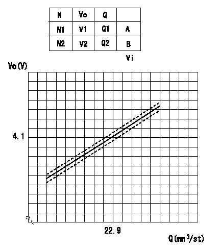
Potentiometer adjustment (oval)
At pump speed N1, measure the injection quantity when the control lever is moved a from the idle position (lever, stopper gap L). Then install the potentiometer.
N:Pump speed
Vo:Output voltage
Q:Injection quantity
A:Adjusting point
B:Checking point
Vi:Applied voltage
----------
N1=700(r/min) a=14.5(deg) L=4.8(mm) Vi=10(V)
----------
N1=700(r/min) N2=500(r/min) V1=4.10(V) V2=3.33(V) Q1=22.9+-1(mm3/st) Q2=(18.6(mm3/st)) Vi=10(V)
----------
N1=700(r/min) a=14.5(deg) L=4.8(mm) Vi=10(V)
----------
N1=700(r/min) N2=500(r/min) V1=4.10(V) V2=3.33(V) Q1=22.9+-1(mm3/st) Q2=(18.6(mm3/st)) Vi=10(V)
Information:
preparatory step: a) separate governor from fuel injection pump housing. 1. Remove the fuel injection pump as follows: a) Remove the protective cap and the felt washer (1). b) Install wrench (A) and remove retaining bushing (2) from housing.c) Remove the seal (3). d) Install extractor (B).e) Lift the fuel injection pump out of the housing.f) Remove the spacer (4). Keep the spacers (4) and pumps together, and identified as to their location in the fuel injection pump housing.2. Disassemble the fuel injection pumps as follows: a) Remove the bonnet (5), ring (6), spring (7), and check valve (8) from the barrel (9).b) Remove the plunger assembly (10), washer (11), and spring (12) from the barrel (9).
While disassembling and assembling fuel injection pump, exercise considerable care to prevent damage to plunger surfaces. The barrel and plunger assemblies are matched, and the individual parts are not interchangeable with other barrels or plunger assemblies.
3. Remove the rack (13).4. Remove the lifters (14). Keep the lifters identified and together with their respective pumps and spacers. 5. Remove the camshaft retaining plate (15), bolt and lock. 6. Remove the spring (16) and the gear assembly (17) from the camshaft. 7. Remove the camshaft (19). 8. Using tool (C), remove the camshaft bearings from the fuel injection pump housing.9. Remove the two rack bearings (18) from the fuel injection pump housing.Assemble Fuel Injection Pump Housing
1. Using tool group (C), install the camshaft bearings in the fuel injection pump housing. Install the bearing in governor end of housing so the oil hole in bearing is aligned with oil hole in housing. Install the camshaft bearings flush with outer ends of fuel injection pump housing. 2. Using tool (D), install the two rack bearings in the fuel injection pump housing. Install the bearing in governor end of housing so it will be recessed .195 .005 in. (4,953 0,127 mm) from face of housing. Install the rack bearing in accessory drive end of housing so it will be flush with face of fuel injection pump housing. 3. Lubricate the camshaft with clean SAE 30 engine oil. Install the camshaft in fuel injection pump housing. 4. Postion the governor drive gear (1) and spring (2) on the camshaft. Install the camshaft retaining plate (3), bolt, and lock. 5. Install the lifters (4) in their respective positions in housing. Lubricate the rack generously with clean SAE 30 engine oil. Install the rack (5) into fuel injection pump housing with the slot in rack toward the governor end of housing.6. Install the spacers in their respective positions in housing. If new lifters and pumps are to be installed, it will be necessary to set the fuel pump timing dimension. See FUEL INJECTION PUMP TIMING DIMENSION SETTING-OFF ENGINE in TESTING AND ADJUSTING.7. Assemble the fuel injection pumps as follows: a) Lubricate all parts generously with clean fuel oil.b) Install the spring, washer, and plunger in the barrel.c) Install the spring, check valve, bonnet, and ring on the barrel.
Do