Information injection-pump assembly
ZEXEL
104740-1320
1047401320
ISUZU
8944240821
8944240821

Rating:
Cross reference number
ZEXEL
104740-1320
1047401320
ISUZU
8944240821
8944240821
Zexel num
Bosch num
Firm num
Name
Calibration Data:
Adjustment conditions
Test oil
1404 Test oil ISO4113orSAEJ967d
1404 Test oil ISO4113orSAEJ967d
Test oil temperature
degC
45
45
50
Nozzle
105000-2010
Bosch type code
NP-DN12SD12TT
Nozzle holder
105780-2080
Opening pressure
MPa
14.7
14.7
15.19
Opening pressure
kgf/cm2
150
150
155
Injection pipe
Inside diameter - outside diameter - length (mm) mm 2-6-840
Inside diameter - outside diameter - length (mm) mm 2-6-840
Transfer pump pressure
kPa
20
20
20
Transfer pump pressure
kgf/cm2
0.2
0.2
0.2
Direction of rotation (viewed from drive side)
Right R
Right R
Injection timing adjustment
Pump speed
r/min
900
900
900
Boost pressure
kPa
40
38.7
41.3
Boost pressure
mmHg
300
290
310
Average injection quantity
mm3/st.
46.3
45.8
46.8
Difference in delivery
mm3/st.
3.5
Basic
*
Remarks
CBS
CBS
Injection timing adjustment_02
Pump speed
r/min
1250
1250
1250
Boost pressure
kPa
79.95
78.6
81.3
Boost pressure
mmHg
600
590
610
Average injection quantity
mm3/st.
48.3
47.8
48.8
Difference in delivery
mm3/st.
4
Basic
*
Remarks
Full
Full
Injection timing adjustment_03
Pump speed
r/min
900
900
900
Boost pressure
kPa
40
38.7
41.3
Boost pressure
mmHg
300
290
310
Average injection quantity
mm3/st.
46.3
45.3
47.3
Remarks
CBS
CBS
Injection timing adjustment_04
Pump speed
r/min
1150
1150
1150
Boost pressure
kPa
79.95
78.6
81.3
Boost pressure
mmHg
600
590
610
Average injection quantity
mm3/st.
49.3
46.8
51.8
Injection timing adjustment_05
Pump speed
r/min
1250
1250
1250
Boost pressure
kPa
0
0
0
Boost pressure
mmHg
0
0
0
Average injection quantity
mm3/st.
37.3
34.8
39.8
Injection timing adjustment_06
Pump speed
r/min
1250
1250
1250
Boost pressure
kPa
79.95
78.6
81.3
Boost pressure
mmHg
600
590
610
Average injection quantity
mm3/st.
48.3
47.3
49.3
Remarks
Full
Full
Injection timing adjustment_07
Pump speed
r/min
2175
2175
2175
Boost pressure
kPa
79.95
78.6
81.3
Boost pressure
mmHg
600
590
610
Average injection quantity
mm3/st.
39.1
36.6
41.6
Injection timing adjustment_08
Pump speed
r/min
2550
2550
2550
Boost pressure
kPa
79.95
78.6
81.3
Boost pressure
mmHg
600
590
610
Average injection quantity
mm3/st.
22.9
19.4
26.4
Injection quantity adjustment
Pump speed
r/min
2550
2550
2550
Boost pressure
kPa
79.95
78.6
81.3
Boost pressure
mmHg
600
590
610
Average injection quantity
mm3/st.
22.9
19.9
25.9
Difference in delivery
mm3/st.
7
Basic
*
Injection quantity adjustment_02
Pump speed
r/min
2800
2800
2800
Boost pressure
kPa
79.95
78.6
81.3
Boost pressure
mmHg
600
590
610
Average injection quantity
mm3/st.
7
Governor adjustment
Pump speed
r/min
375
375
375
Boost pressure
kPa
0
0
0
Boost pressure
mmHg
0
0
0
Average injection quantity
mm3/st.
11.3
9.3
13.3
Difference in delivery
mm3/st.
2
Basic
*
Governor adjustment_02
Pump speed
r/min
375
375
375
Boost pressure
kPa
0
0
0
Boost pressure
mmHg
0
0
0
Average injection quantity
mm3/st.
11.3
9.3
13.3
Governor adjustment_03
Pump speed
r/min
600
600
600
Boost pressure
kPa
0
0
0
Boost pressure
mmHg
0
0
0
Average injection quantity
mm3/st.
3
Timer adjustment
Pump speed
r/min
100
100
100
Boost pressure
kPa
0
0
0
Boost pressure
mmHg
0
0
0
Average injection quantity
mm3/st.
60
60
Basic
*
Speed control lever angle
Pump speed
r/min
375
375
375
Boost pressure
kPa
0
0
0
Boost pressure
mmHg
0
0
0
Average injection quantity
mm3/st.
0
0
0
Remarks
Magnet OFF
Magnet OFF
0000000901
Pump speed
r/min
1250
1250
1250
Boost pressure
kPa
0
0
0
Boost pressure
mmHg
0
0
0
Overflow quantity
cm3/min
399
270
528
Stop lever angle
Pump speed
r/min
1250
1250
1250
Boost pressure
kPa
0
0
0
Boost pressure
mmHg
0
0
0
Pressure
kPa
470.5
451
490
Pressure
kgf/cm2
4.8
4.6
5
Basic
*
Stop lever angle_02
Pump speed
r/min
250
250
250
Boost pressure
kPa
0
0
0
Boost pressure
mmHg
0
0
0
Pressure
kPa
206
177
235
Pressure
kgf/cm2
2.1
1.8
2.4
Stop lever angle_03
Pump speed
r/min
1250
1250
1250
Boost pressure
kPa
0
0
0
Boost pressure
mmHg
0
0
0
Pressure
kPa
470.5
451
490
Pressure
kgf/cm2
4.8
4.6
5
Stop lever angle_04
Pump speed
r/min
2150
2150
2150
Boost pressure
kPa
0
0
0
Boost pressure
mmHg
0
0
0
Pressure
kPa
676.5
647
706
Pressure
kgf/cm2
6.9
6.6
7.2
0000001101
Pump speed
r/min
1250
1250
1250
Boost pressure
kPa
0
0
0
Boost pressure
mmHg
0
0
0
Timer stroke
mm
3
2.8
3.2
Basic
*
_02
Pump speed
r/min
875
775
975
Boost pressure
kPa
0
0
0
Boost pressure
mmHg
0
0
0
Timer stroke
mm
0.5
0.5
0.5
_03
Pump speed
r/min
1250
1250
1250
Boost pressure
kPa
0
0
0
Boost pressure
mmHg
0
0
0
Timer stroke
mm
3
2.7
3.3
_04
Pump speed
r/min
1700
1700
1700
Boost pressure
kPa
0
0
0
Boost pressure
mmHg
0
0
0
Timer stroke
mm
6
5.5
6.5
_05
Pump speed
r/min
2150
2150
2150
Boost pressure
kPa
0
0
0
Boost pressure
mmHg
0
0
0
Timer stroke
mm
9
8.6
9.4
0000001201
Max. applied voltage
V
8
8
8
Test voltage
V
13
12
14
Timing setting
K dimension
mm
3.3
3.2
3.4
KF dimension
mm
5.8
5.7
5.9
MS dimension
mm
1.6
1.5
1.7
BCS stroke
mm
2.9
2.8
3
Control lever angle alpha
deg.
17
13
21
Control lever angle beta
deg.
42
37
47
Test data Ex:
0000001801 V-FICD ADJUSTMENT
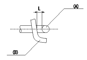
Adjustment of the V-FICD
1. Adjust the actuator rod to obtain L1.
2. Apply negative pressure P1 {P2} to the actuator and confirm that it moves through its full stroke.
(A) actuator shaft
(B) Control lever
----------
L=1+1mm P1=-53.3kPa P2=-400mmHg
----------
L=1+1mm
----------
L=1+1mm P1=-53.3kPa P2=-400mmHg
----------
L=1+1mm
Information:
Crankshaft Gear Removal
Remove the gear using an 8B7548 Push Puller, 8B7551 Bearing Pulling Attachment, 8B7561 Step Plate, and 8H684 Ratchet Box Wrench.
PULLING CRANKSHAFT GEARThe 1P820 Hydraulic Puller Group can also be used to pull gear from crankshaft. Tools required are 1P820 Hydraulic Puller Group, 8B7551 Bearing Pulling Attachment, 8B7549 Puller legs (two), 8B7561 Step Plate, 3H465 Plate (four), 1B4207 Nut (two), and 9S5800 Pump Group.
USING HYDRAULIC PULLERCrankshaft Gear Installation
1. Install the key in keyway of crankshaft. Remove all burrs from key and keyway inside of crankshaft gear.2. Heat gear to 500° F. (260° C) maximum.3. Install gear on crankshaft with timing mark on gear facing front of crankshaft.Crankshaft Wear Sleeve Removal
REMOVING WEAR SLEEVEUse the 8S7164 Wear Sleeve Puller Group to remove the wear sleeve.Crankshaft Wear Sleeve Installation
WEAR SLEEVE INSTALLATION TOOLS
1. 5P290 Pilot. 2. 5P286 Ring. 3. 9S8858 Nut. 4. 1P5515 Bolts. 5. 9S8864 Pusher Plate.To install the wear sleeve, use the following procedure:1. Install 5P290 Pilot (1) on the end of the crankshaft. Install 1P5515 Bolts (4) and tighten just enough to hold pilot (1) yet allow some side movement. Put the wear sleeve on pilot (1) with the chamfer toward the rear of the engine. Push the wear sleeve on the crankshaft to put pilot (1) in the center, then tighten bolts (4).2. Put 5P286 Ring (2) on 9S8864 Pusher Plate (5) and place this assembly on the stud of pilot (1). Install 9S8858 Nut (3) and tighten nut to push wear sleeve on to the crankshaft.Crankshaft Rear Oil Seal Removal
Use the 1P3075 Puller Group to remove the crankshaft rear seal.
REMOVING REAR OIL SEAL (Typical Example)Crankshaft Rear Oil Seal Installation
REAR OIL SEAL INSTALLATION TOOLS
1. 5P290 Pilot. 2. 1P5515 Bolts. 3. 5P285 Ring. 4. 9S8858 Nut. 5. 5P288 Ring. 6. 9S8864 Pusher Plate.To install the crankshaft rear oil seal, use the following procedure:1. Install 5P290 Pilot (1) on the crankshaft with 1P5515 Bolts (2). Install 5P288 Ring (5) on pilot (1).2. Put 7F2770 Cement on the outer diameter of the seal metal shell. Put engine oil on the lip of the seal. Install the seal on the pilot with the lip of the seal toward the front of the engine.3. Install 9S8864 Pusher Plate (6) and 5P285 Ring (3) over pilot (1). Install 9S8858 Nut (4). Tighten nut (4) until ring (5) makes contact with the flywheel housing. To prevent possible oil leakage, install a new wear sleeve each time the rear oil seal is replaced.Crankshaft Front Oil Seal (1100, 3100, and 3208 Engines 79V1-79V1407)
The crankshaft front oil seal can be removed with the timing gear cover on or off the engine. To install the seal to the proper depth, the timing gear cover must be on the engine.A new timing gear cover permits the crankshaft front oil seal to be installed to two depths.Use the 9S6030 Installation Group which includes the 8S2276 Installer and 9S6012 Spacer to install the seal. To install seal to the original depth, use only the 8S2276 Installer. To obtain an additional wear