Information injection-pump assembly
ZEXEL
104740-1250
1047401250
ISUZU
8944192650
8944192650

Rating:
Cross reference number
ZEXEL
104740-1250
1047401250
ISUZU
8944192650
8944192650
Zexel num
Bosch num
Firm num
Name
Calibration Data:
Adjustment conditions
Test oil
1404 Test oil ISO4113orSAEJ967d
1404 Test oil ISO4113orSAEJ967d
Test oil temperature
degC
45
45
50
Nozzle
105000-2010
Bosch type code
NP-DN12SD12TT
Nozzle holder
105780-2080
Opening pressure
MPa
14.7
14.7
15.19
Opening pressure
kgf/cm2
150
150
155
Injection pipe
Inside diameter - outside diameter - length (mm) mm 2-6-840
Inside diameter - outside diameter - length (mm) mm 2-6-840
Transfer pump pressure
kPa
20
20
20
Transfer pump pressure
kgf/cm2
0.2
0.2
0.2
Direction of rotation (viewed from drive side)
Right R
Right R
Injection timing adjustment
Pump speed
r/min
1250
1250
1250
Boost pressure
kPa
60
58.7
61.3
Boost pressure
mmHg
450
440
460
Average injection quantity
mm3/st.
51.1
50.6
51.6
Difference in delivery
mm3/st.
4
Basic
*
Injection timing adjustment_02
Pump speed
r/min
750
750
750
Boost pressure
kPa
24
22.7
25.3
Boost pressure
mmHg
180
170
190
Average injection quantity
mm3/st.
42.1
41.6
42.6
Difference in delivery
mm3/st.
5
Basic
*
Injection timing adjustment_03
Pump speed
r/min
2600
2600
2600
Boost pressure
kPa
60
58.7
61.3
Boost pressure
mmHg
450
440
460
Average injection quantity
mm3/st.
17.6
16.1
19.1
Injection timing adjustment_04
Pump speed
r/min
2250
2250
2250
Boost pressure
kPa
60
58.7
61.3
Boost pressure
mmHg
450
440
460
Average injection quantity
mm3/st.
41.6
38.6
44.6
Injection timing adjustment_05
Pump speed
r/min
2150
2150
2150
Boost pressure
kPa
60
58.7
61.3
Boost pressure
mmHg
450
440
460
Average injection quantity
mm3/st.
43.2
40.7
45.7
Injection timing adjustment_06
Pump speed
r/min
1250
1250
1250
Boost pressure
kPa
60
58.7
61.3
Boost pressure
mmHg
450
440
460
Average injection quantity
mm3/st.
51.1
50.1
52.1
Injection timing adjustment_07
Pump speed
r/min
1250
1250
1250
Boost pressure
kPa
0
0
0
Boost pressure
mmHg
0
0
0
Average injection quantity
mm3/st.
36.4
33.9
38.9
Injection timing adjustment_08
Pump speed
r/min
750
750
750
Boost pressure
kPa
24
22.7
25.3
Boost pressure
mmHg
180
170
190
Average injection quantity
mm3/st.
42.1
41.1
43.1
Injection timing adjustment_09
Pump speed
r/min
550
550
550
Boost pressure
kPa
0
0
0
Boost pressure
mmHg
0
0
0
Average injection quantity
mm3/st.
38.2
35.7
40.7
Injection quantity adjustment
Pump speed
r/min
2600
2600
2600
Boost pressure
kPa
60
58.7
61.3
Boost pressure
mmHg
450
440
460
Average injection quantity
mm3/st.
17.6
16.6
18.6
Difference in delivery
mm3/st.
5.5
Basic
*
Injection quantity adjustment_02
Pump speed
r/min
2800
2800
2800
Boost pressure
kPa
60
58.7
61.3
Boost pressure
mmHg
450
440
460
Average injection quantity
mm3/st.
5
Governor adjustment
Pump speed
r/min
400
400
400
Boost pressure
kPa
0
0
0
Boost pressure
mmHg
0
0
0
Average injection quantity
mm3/st.
12.2
10.2
14.2
Difference in delivery
mm3/st.
2
Basic
*
Governor adjustment_02
Pump speed
r/min
400
400
400
Boost pressure
kPa
0
0
0
Boost pressure
mmHg
0
0
0
Average injection quantity
mm3/st.
12.2
10.2
14.2
Governor adjustment_03
Pump speed
r/min
575
575
575
Boost pressure
kPa
0
0
0
Boost pressure
mmHg
0
0
0
Average injection quantity
mm3/st.
3
Timer adjustment
Pump speed
r/min
100
100
100
Boost pressure
kPa
0
0
0
Boost pressure
mmHg
0
0
0
Average injection quantity
mm3/st.
77.5
60
95
Basic
*
Speed control lever angle
Pump speed
r/min
400
400
400
Boost pressure
kPa
0
0
0
Boost pressure
mmHg
0
0
0
Average injection quantity
mm3/st.
0
0
0
Remarks
Magnet OFF
Magnet OFF
0000000901
Pump speed
r/min
1250
1250
1250
Boost pressure
kPa
0
0
0
Boost pressure
mmHg
0
0
0
Overflow quantity
cm3/min
400
270
530
Stop lever angle
Pump speed
r/min
1250
1250
1250
Boost pressure
kPa
60
58.7
61.3
Boost pressure
mmHg
450
440
460
Pressure
kPa
441.5
422
461
Pressure
kgf/cm2
4.5
4.3
4.7
Basic
*
Stop lever angle_02
Pump speed
r/min
600
600
600
Boost pressure
kPa
60
58.7
61.3
Boost pressure
mmHg
450
440
460
Pressure
kPa
255
226
284
Pressure
kgf/cm2
2.6
2.3
2.9
Stop lever angle_03
Pump speed
r/min
1250
1250
1250
Boost pressure
kPa
60
58.7
61.3
Boost pressure
mmHg
450
440
460
Pressure
kPa
441.5
422
461
Pressure
kgf/cm2
4.5
4.3
4.7
Stop lever angle_04
Pump speed
r/min
1750
1750
1750
Boost pressure
kPa
60
58.7
61.3
Boost pressure
mmHg
450
440
460
Pressure
kPa
578.5
549
608
Pressure
kgf/cm2
5.9
5.6
6.2
Stop lever angle_05
Pump speed
r/min
2250
2250
2250
Boost pressure
kPa
60
58.7
61.3
Boost pressure
mmHg
450
440
460
Pressure
kPa
730.5
686
775
Pressure
kgf/cm2
7.45
7
7.9
0000001101
Pump speed
r/min
1250
1250
1250
Boost pressure
kPa
60
58.7
61.3
Boost pressure
mmHg
450
440
460
Timer stroke
mm
2.6
2.4
2.8
Basic
*
_02
Pump speed
r/min
1250
1250
1250
Boost pressure
kPa
60
58.7
61.3
Boost pressure
mmHg
450
440
460
Timer stroke
mm
2.6
2.3
2.9
_03
Pump speed
r/min
1750
1750
1750
Boost pressure
kPa
60
58.7
61.3
Boost pressure
mmHg
450
440
460
Timer stroke
mm
5.2
4.6
5.8
_04
Pump speed
r/min
2250
2250
2250
Boost pressure
kPa
60
58.7
61.3
Boost pressure
mmHg
450
440
460
Timer stroke
mm
7.8
7.4
8.2
0000001201
Max. applied voltage
V
8
8
8
Test voltage
V
13
12
14
0000001401
Pump speed
r/min
1250
1250
1250
Boost pressure
kPa
60
58.7
61.3
Boost pressure
mmHg
450
440
460
Average injection quantity
mm3/st.
30
29
31
Timer stroke variation dT
mm
1
0.8
1.2
Basic
*
_02
Pump speed
r/min
1250
1250
1250
Boost pressure
kPa
60
58.7
61.3
Boost pressure
mmHg
450
440
460
Average injection quantity
mm3/st.
30
28.5
31.5
Timer stroke variation dT
mm
1
0.7
1.3
_03
Pump speed
r/min
1250
1250
1250
Boost pressure
kPa
60
58.7
61.3
Boost pressure
mmHg
450
440
460
Average injection quantity
mm3/st.
23
21.5
24.5
Timer stroke variation dT
mm
1.6
1.1
2.1
Timing setting
K dimension
mm
3.3
3.2
3.4
KF dimension
mm
5.8
5.7
5.9
MS dimension
mm
1.3
1.2
1.4
BCS stroke
mm
4.2
4.1
4.3
Control lever angle alpha
deg.
24.5
20.5
28.5
Control lever angle beta
deg.
40.5
35.5
45.5
Test data Ex:
0000001801 W-CSD ADJUSTMENT

Adjustment of the W-CSD
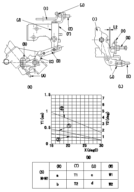
1. Adjustment of the timer stroke
Adjust using screw (A) so that the timer stroke is the value determined using the graph (M). [(K), (M)]
2. Adjustment of the position of the intermediate lever.
Insert a shim (J) L1 between the control lever (I) and the FICD screw (E).
Insert a shim L2 between the control lever (I) and the idle set screw (G).
Align the intermediate lever (F) with the aligning line. Fix the screw (E) so that it contacts the control lever (F). [(K), (L)]
3. Adjustment of the FICD
With the shim (J) inserted, insert a shim L3 between the control lever (I) and the idle set screw (G).
Use adjusting screw (B) to fix the CSD lever (C) in the position where it operates the intermediate lever (F) via the rod (D). [(K), (L), (M)]
(O) = timer stroke adjustment (mm) - (1): TA = -0.0215t+0.75
(P) = lever angle (deg) - (2): theta = -0.1925t + 7.71
(Q) = Lever position (mm): L = -0.0635t+2.52
The (Q) indicates the clearance between the control lever and the idle set screw.
(R) = cooling water temperature (deg C)
(S) = cooling water temperature: increase direction
N = pump speed
X = temperature t (deg C)
Y1 = timer stroke TA (mm)
Y2 = control lever angle theta, L (deg mm)
(K) = Figure 1
(L) = Figure 2
(M) = Figure 3
(T) = Timer piston stroke (mm)
(U) = Lever angle (deg)
(W) = Lever position (mm)
----------
L1=1.9+-0.05mm L2=1.25+-0.05mm L3=L2+-0.05mm
----------
N1=100r/min a=20degC b=-20degC c=3.9+-1deg d=(11.6+-3)deg T1=0.3+0.4-0.2mm T2=1.2+0.6-0.4mm W1=1.3+-0.3mm W2=(3.8+-1)mm
----------
L1=1.9+-0.05mm L2=1.25+-0.05mm L3=L2+-0.05mm
----------
N1=100r/min a=20degC b=-20degC c=3.9+-1deg d=(11.6+-3)deg T1=0.3+0.4-0.2mm T2=1.2+0.6-0.4mm W1=1.3+-0.3mm W2=(3.8+-1)mm
Information:
REMOVING CONNECTING ROD BEARING CAP4. Push the piston and connecting rod upward until the piston rings clear the cylinder block. Remove the piston and connecting rod from the cylinder block.
REMOVING PISTON
Do not allow the connecting rods to hit the bottom edge of the cylinder bores or crankshaft journals when removing or installing. Check the lower portion of the bores for burrs or scratches. Use crocus cloth to remove any burrs or scratches from bottom edge of the bores.
5. Keep the connecting rod bearing cap with its respective connecting rod and piston.6. Repeat Steps 2 through 5 for the remaining pistons.Install Pistons
1. Rotate the crankshaft to position bearing journal of the piston to be installed.2. Lubricate the crankshaft bearing journal, bore in cylinder block, piston, rings, and connecting rod bearings with clean engine oil (SAE 30).3. Install a 1Y7426 Ring Compressor (3), or the 4S9450 Compressor (1) and the 4S9446 Clamp (2) from the 4S9458 Teflon Seal Tool Group, on the piston to compress the rings. Install the piston and connecting rod in cylinder bore with piston crater toward vee of engine. Guide the lower end of connecting rod over the crankshaft journal to prevent damage to the crankshaft.
INSTALLING PISTON
1. 4S9450 Compressor. 2. 4S9446 Clamp.
INSTALLING PISTON ALTERNATE METHOD
3. 1Y7426 Ring Compressor.4. Install the connecting rod cap to connecting rod so numbers correspond and both numbers appear on the same side. Lubricate bolt threads, seating faces of cap and nuts, install the retaining nuts and tighten to 30 3 lb. ft. (4.1 0.4 mkg). Mark cap and nut with matching marks. Tighten additional from mark 60° 5°.5. Repeat Steps 1 thru 4 for the remaining pistons.Disassemble Piston
PISTON ASSEMBLY1. Use ring expander (1) to remove rings.
REMOVING RINGS
1. 5F9059 Ring Expander.2. Remove snap ring (5) and push piston pin (2) out of piston (4) and connecting rod (3).
PISTON DISASSEMBLED
2. Piston pin. 3. Connecting rod. 4. Piston. 5. Snap ring.Assemble Piston
1. Install connecting rod into piston with boss on rod on same side as crater in piston crown.
CONNECTING ROD AND PISTON
CONNECTING ROD AND PISTON Installation of connecting rods WITHOUT BOSS on rod; Install connecting rod into piston with cylinder identification number (as marked on the lower end of the rod and on the cap) 180° opposite the crater in piston crown.2. Install piston pin and snap rings.3. Use the 8S2304 Piston Ring Groove Cleaner to clean the piston ring grooves before installing piston rings.4. Install oil ring spring (6) before installing oil ring.
8S2304 RING GROOVE CLEANER
INSTALLING OIL RING SPRING
6. Oil ring spring.5. Use a 5F9059 Ring Expander to install piston rings. Install compression ring with side marked "TOP" toward top of piston. Install oil ring with gap 180° from oil ring spring joint and approximately 120° from compression ring gap.