Information injection-pump assembly
ZEXEL
104740-1190
1047401190
ISUZU
8941782080
8941782080
Rating:
Cross reference number
ZEXEL
104740-1190
1047401190
ISUZU
8941782080
8941782080
Zexel num
Bosch num
Firm num
Name
104740-1190
8941782080 ISUZU
INJECTION-PUMP ASSEMBLY
4FC1-J *
4FC1-J *
Calibration Data:
Adjustment conditions
Test oil
1404 Test oil ISO4113orSAEJ967d
1404 Test oil ISO4113orSAEJ967d
Test oil temperature
degC
45
45
50
Nozzle
105000-2010
Bosch type code
NP-DN12SD12TT
Nozzle holder
105780-2080
Opening pressure
MPa
14.7
14.7
15.19
Opening pressure
kgf/cm2
150
150
155
Injection pipe
Inside diameter - outside diameter - length (mm) mm 2-6-840
Inside diameter - outside diameter - length (mm) mm 2-6-840
Transfer pump pressure
kPa
20
20
20
Transfer pump pressure
kgf/cm2
0.2
0.2
0.2
Direction of rotation (viewed from drive side)
Right R
Right R
Injection timing adjustment
Pump speed
r/min
900
900
900
Boost pressure
kPa
37.3
36
38.6
Boost pressure
mmHg
280
270
290
Average injection quantity
mm3/st.
47.5
47
48
Difference in delivery
mm3/st.
4
Basic
*
Oil temperature
degC
50
48
52
Remarks
CBS
CBS
Injection timing adjustment_02
Pump speed
r/min
1250
1250
1250
Boost pressure
kPa
60
58.7
61.3
Boost pressure
mmHg
450
440
460
Average injection quantity
mm3/st.
51.3
50.8
51.8
Difference in delivery
mm3/st.
4
Basic
*
Oil temperature
degC
50
48
52
Remarks
Full
Full
Injection timing adjustment_03
Pump speed
r/min
550
550
550
Boost pressure
kPa
0
0
0
Boost pressure
mmHg
0
0
0
Average injection quantity
mm3/st.
37.4
35.4
39.4
Oil temperature
degC
50
48
52
Injection timing adjustment_04
Pump speed
r/min
900
900
900
Boost pressure
kPa
37.3
36
38.6
Boost pressure
mmHg
280
270
290
Average injection quantity
mm3/st.
47.5
46.5
48.5
Difference in delivery
mm3/st.
4
Basic
*
Oil temperature
degC
50
48
52
Injection timing adjustment_05
Pump speed
r/min
1250
1250
1250
Boost pressure
kPa
60
58.7
61.3
Boost pressure
mmHg
450
440
460
Average injection quantity
mm3/st.
51.3
50.3
52.3
Difference in delivery
mm3/st.
4
Basic
*
Oil temperature
degC
50
48
52
Injection timing adjustment_06
Pump speed
r/min
1250
1250
1250
Boost pressure
kPa
0
0
0
Boost pressure
mmHg
0
0
0
Average injection quantity
mm3/st.
39.7
37.7
41.7
Difference in delivery
mm3/st.
3.5
Oil temperature
degC
50
48
52
Injection timing adjustment_07
Pump speed
r/min
2150
2150
2150
Boost pressure
kPa
60
58.7
61.3
Boost pressure
mmHg
450
440
460
Average injection quantity
mm3/st.
45.7
43.7
47.7
Difference in delivery
mm3/st.
5.5
Oil temperature
degC
52
50
54
Injection quantity adjustment
Pump speed
r/min
2600
2600
2600
Boost pressure
kPa
60
58.7
61.3
Boost pressure
mmHg
450
440
460
Average injection quantity
mm3/st.
17.5
16.5
18.5
Difference in delivery
mm3/st.
5.5
Basic
*
Oil temperature
degC
55
52
58
Injection quantity adjustment_02
Pump speed
r/min
2800
2800
2800
Boost pressure
kPa
60
58.7
61.3
Boost pressure
mmHg
450
440
460
Average injection quantity
mm3/st.
5
Oil temperature
degC
55
52
58
Injection quantity adjustment_03
Pump speed
r/min
2600
2600
2600
Boost pressure
kPa
60
58.7
61.3
Boost pressure
mmHg
450
440
460
Average injection quantity
mm3/st.
17.5
14.5
20.5
Difference in delivery
mm3/st.
5.5
Oil temperature
degC
55
52
58
Governor adjustment
Pump speed
r/min
400
400
400
Boost pressure
kPa
0
0
0
Boost pressure
mmHg
0
0
0
Average injection quantity
mm3/st.
12.2
10.2
14.2
Difference in delivery
mm3/st.
2
Basic
*
Oil temperature
degC
48
46
50
Governor adjustment_02
Pump speed
r/min
400
400
400
Boost pressure
kPa
0
0
0
Boost pressure
mmHg
0
0
0
Average injection quantity
mm3/st.
12.2
10.2
14.2
Difference in delivery
mm3/st.
2
Oil temperature
degC
48
46
50
Timer adjustment
Pump speed
r/min
100
100
100
Boost pressure
kPa
0
0
0
Boost pressure
mmHg
0
0
0
Average injection quantity
mm3/st.
60
60
Basic
*
Oil temperature
degC
48
46
50
Remarks
Full
Full
Timer adjustment_02
Pump speed
r/min
100
100
100
Boost pressure
kPa
0
0
0
Boost pressure
mmHg
0
0
0
Average injection quantity
mm3/st.
60
60
Oil temperature
degC
48
46
50
Speed control lever angle
Pump speed
r/min
400
400
400
Boost pressure
kPa
0
0
0
Boost pressure
mmHg
0
0
0
Average injection quantity
mm3/st.
0
0
0
Oil temperature
degC
48
46
50
Remarks
Magnet OFF at idling position
Magnet OFF at idling position
0000000901
Pump speed
r/min
1250
1250
1250
Boost pressure
kPa
0
0
0
Boost pressure
mmHg
0
0
0
Overflow quantity
cm3/min
400
270
530
Oil temperature
degC
50
48
52
Stop lever angle
Pump speed
r/min
1250
1250
1250
Boost pressure
kPa
0
0
0
Boost pressure
mmHg
0
0
0
Pressure
kPa
441
421
461
Pressure
kgf/cm2
4.5
4.3
4.7
Basic
*
Oil temperature
degC
50
48
52
Stop lever angle_02
Pump speed
r/min
1250
1250
1250
Boost pressure
kPa
0
0
0
Boost pressure
mmHg
0
0
0
Pressure
kPa
441
412
470
Pressure
kgf/cm2
4.5
4.2
4.8
Basic
*
Oil temperature
degC
50
48
52
Stop lever angle_03
Pump speed
r/min
1750
1750
1750
Boost pressure
kPa
0
0
0
Boost pressure
mmHg
0
0
0
Pressure
kPa
598
569
627
Pressure
kgf/cm2
6.1
5.8
6.4
Oil temperature
degC
50
48
52
0000001101
Pump speed
r/min
1250
1250
1250
Boost pressure
kPa
0
0
0
Boost pressure
mmHg
0
0
0
Timer stroke
mm
2.6
2.4
2.8
Basic
*
Oil temperature
degC
50
48
52
_02
Pump speed
r/min
840
740
940
Boost pressure
kPa
0
0
0
Boost pressure
mmHg
0
0
0
Timer stroke
mm
0.5
0.5
0.5
Oil temperature
degC
50
48
52
_03
Pump speed
r/min
1250
1250
1250
Boost pressure
kPa
0
0
0
Boost pressure
mmHg
0
0
0
Timer stroke
mm
2.6
2.4
2.8
Basic
*
Oil temperature
degC
50
48
52
_04
Pump speed
r/min
1750
1750
1750
Boost pressure
kPa
0
0
0
Boost pressure
mmHg
0
0
0
Timer stroke
mm
5.2
4.8
5.6
Oil temperature
degC
50
48
52
_05
Pump speed
r/min
2250
2250
2250
Boost pressure
kPa
0
0
0
Boost pressure
mmHg
0
0
0
Timer stroke
mm
7.8
7.5
8.2
Oil temperature
degC
52
50
54
0000001201
Max. applied voltage
V
8
8
8
Test voltage
V
13
12
14
0000001401
Pump speed
r/min
1250
1250
1250
Boost pressure
kPa
0
0
0
Boost pressure
mmHg
0
0
0
Average injection quantity
mm3/st.
30
29
31
Timer stroke TA
mm
1.6
1.6
1.6
Timer stroke variation dT
mm
1
0.8
1.2
Basic
*
Oil temperature
degC
50
48
52
_02
Pump speed
r/min
1250
1250
1250
Boost pressure
kPa
0
0
0
Boost pressure
mmHg
0
0
0
Average injection quantity
mm3/st.
30
29
31
Timer stroke variation dT
mm
1
0.6
1.4
Basic
*
Oil temperature
degC
50
48
52
_03
Pump speed
r/min
1250
1250
1250
Boost pressure
kPa
0
0
0
Boost pressure
mmHg
0
0
0
Average injection quantity
mm3/st.
25
24
26
Timer stroke variation dT
mm
1.55
1.15
1.95
Oil temperature
degC
50
48
52
Timing setting
K dimension
mm
3.3
3.2
3.4
KF dimension
mm
5.8
5.7
5.9
MS dimension
mm
1.3
1.2
1.4
BCS stroke
mm
3.5
3.3
3.7
Control lever angle alpha
deg.
23
19
27
Control lever angle beta
deg.
45
40
50
Test data Ex:
0000001801 MICROSWITCH ADJUSTMENT
Microswitch adjustment
With the control lever 'a' from the idle position (idle stopper lever clearance L), adjust the position of the microswitch and fix it in the position where it goes OFF.
After adjustment, the microswitch must not turn OFF at lever position between idle and a.
Also, the microswitch lever must not contact the stopper.
----------
a=26+-1deg L=8.5+-0.2mm
----------
----------
a=26+-1deg L=8.5+-0.2mm
----------
0000001901 W-CSD ADJUSTMENT
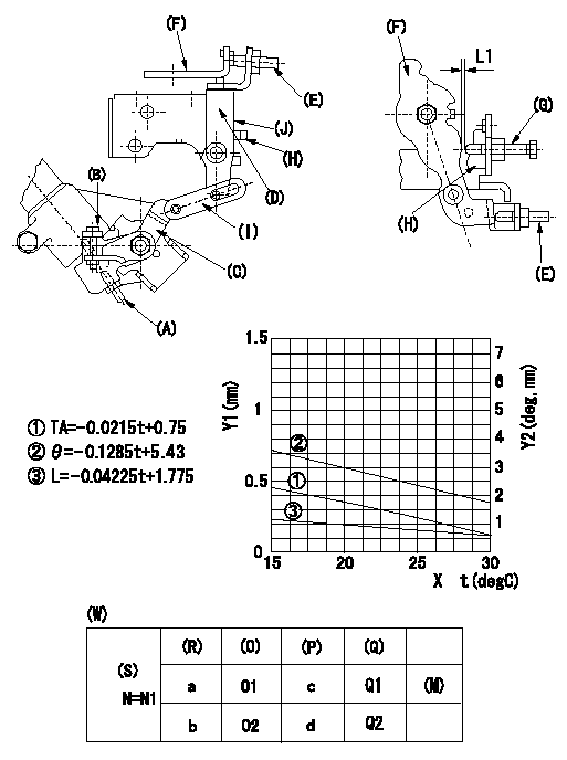
Adjustment of the W-CSD
1. Adjustment of the timer stroke
Adjust screw (A) so that the timer stroke is the value determined from the graph.
2. Adjustment of the position of the intermediate lever.
(1)Insert a shim L1 between the control lever (F) and the idle set screw (G).
(2)Set intermediate lever (D) adjusting screw (E) so that adjusting screw (E) contacts control lever, and so that when intermediate lever is at right angles to pump center, intermediate lever and idle stopper bracket (H) overlap at position (J).
3. W-CSD adjustment
Insert a shim L1+-0.05 between the control lever (F) and the idle set screw (G).
Use adjusting screw (B) to fix the CSD lever (C) in the position where it operates the intermediate lever (D) via the rod (I).
X:Temperature t (deg C)
Y1:Timer stroke TA (mm)
Y2:Control lever position at theta L (deg, mm)
(W) Cold advancer
(R) Cooling water temperature (deg C)
(S) Cooling water temperature: increase direction
(O) Timer piston stroke (mm)
(P) Lever position (deg)
(Q) lever position (mm)
(M) standard point
N:Pump speed
----------
L1=0.93+-0.05mm
----------
N1=500r/min a=20degC b=-20degC c=2.9+-1deg d=8+-3deg O1=0.3+-0.4mm O2=1.2+-0.6mm Q1=0.93+-0.3mm Q2=2.62+-1mm
----------
L1=0.93+-0.05mm
----------
N1=500r/min a=20degC b=-20degC c=2.9+-1deg d=8+-3deg O1=0.3+-0.4mm O2=1.2+-0.6mm Q1=0.93+-0.3mm Q2=2.62+-1mm
Information:
TIMING PIN HOLE PLUG (Typical Example)
1. Plug.2. Rotate the crankshaft CLOCKWISE (as viewed from front of engine) until the timing pin drops into the timing slot in the fuel injection pump camshaft.3. Disconnect wire (2) from fuel shut off solenoid.4. Remove the tachometer drive adapter housing (3).
WIRE AND HOUSING (Typical Example)
2. Wire. 3. Tachometer drive adapter housing.5. Use ratchet (4) and socket (5) to remove the tachometer drive adapter shaft.
REMOVING SHAFT
4. 8H8572 Ratchet. 5. 9S5031 Deep Well Socket.6. Using puller group (6), thread the 9S8528 Bolt Assembly into the camshaft. Do not force the bolt assembly. It should thread easily. Install the 9S8527 Bolt by threading it into the gear carrier or adapter. Then tighten the 9S8527 Bolt with a wrench until the gear carrier or adapter "pops" loose. Remove the 9S8520 Puller Group.
LOOSENING CAMSHAFT DRIVE GEAR
6. 9S8520 Puller Group.7. Remove the plug from the timing hole (8) in the front cover and insert bolt (7). The cover retaining bolt from hole (9) may be used.8. Rotate crankshaft CLOCKWISE (as viewed from front of engine) until bolt (7) threads into the timing gear and is centered in timing hole (8). With timing pin in slot in fuel pump camshaft and the bolt (7) through the front cover and threaded into the timing gear, the fuel injection pump camshaft is timed to the engine.
INSTALLING BOLT
7. 1D4539 Bolt [5/16 in. - 18 NC, 2.5 in. (63.5 mm) long]. 8. Timing hole. 9. Hole.9. Remove the fuel injection pump housing retaining bolts (10).
RETAINING BOLTS (Typical Example)
10. Retaining bolts (three).
REMOVING HOUSING (Typical Example)10. Attach a hoist and remove the fuel injection pump housing and governor as a unit, the weight is approx. 55 lbs. (23 kg).Install Fuel Injection Pump Housing and Governor
1. Attach a hoist and install the fuel injection pump housing and governor as a unit. Install the fuel injection pump housing retaining bolts.2. Install the tachometer drive adapter shaft and tighten shaft retaining nut to 32 2 lb. ft. (4.4 0.3 mkg).3. To check timing remove the timing pin and the bolt. Rotate the crankshaft two revolutions CLOCKWISE (as viewed from front of engine) and install the timing pin and bolt back in place. If the timing pin or bolt can not be installed, the fuel injection pump camshaft must be retimed.4. Remove the bolt (7) from the timing gear and install in hole (9). Install the plug into timing hole (8).5. Remove the timing pin from the timing slot in the fuel injection pump camshaft and install the plug in the timing hole.6. Install the tachometer drive adapter housing. Connect the wire to the fuel shut off solenoid.
Have questions with 104740-1190?
Group cross 104740-1190 ZEXEL
Isuzu
Isuzu
Isuzu
104740-1190
8941782080
INJECTION-PUMP ASSEMBLY
4FC1-J
4FC1-J