Information injection-pump assembly
ZEXEL
104740-1100
1047401100
ISUZU
8941323760
8941323760
Rating:
Cross reference number
ZEXEL
104740-1100
1047401100
ISUZU
8941323760
8941323760
Zexel num
Bosch num
Firm num
Name
104740-1100
8941323760 ISUZU
INJECTION-PUMP ASSEMBLY
C223T * K
C223T * K
Calibration Data:
Adjustment conditions
Test oil
1404 Test oil ISO4113orSAEJ967d
1404 Test oil ISO4113orSAEJ967d
Test oil temperature
degC
45
45
50
Nozzle
105000-2010
Bosch type code
NP-DN12SD12TT
Nozzle holder
105780-2080
Opening pressure
MPa
14.7
14.7
15.19
Opening pressure
kgf/cm2
150
150
155
Injection pipe
Inside diameter - outside diameter - length (mm) mm 2-6-840
Inside diameter - outside diameter - length (mm) mm 2-6-840
Transfer pump pressure
kPa
20
20
20
Transfer pump pressure
kgf/cm2
0.2
0.2
0.2
Direction of rotation (viewed from drive side)
Right R
Right R
Injection timing adjustment
Pump speed
r/min
900
900
900
Boost pressure
kPa
40
38.7
41.3
Boost pressure
mmHg
300
290
310
Average injection quantity
mm3/st.
43.4
42.9
43.9
Difference in delivery
mm3/st.
3.5
Basic
*
Oil temperature
degC
50
48
52
Remarks
CBS
CBS
Injection timing adjustment_02
Pump speed
r/min
1250
1250
1250
Boost pressure
kPa
80
78.7
81.3
Boost pressure
mmHg
600
590
610
Average injection quantity
mm3/st.
48
47.5
48.5
Difference in delivery
mm3/st.
4
Basic
*
Oil temperature
degC
50
48
52
Remarks
Full
Full
Injection timing adjustment_03
Pump speed
r/min
900
900
900
Boost pressure
kPa
40
38.7
41.3
Boost pressure
mmHg
300
290
310
Average injection quantity
mm3/st.
43.4
42.4
44.4
Difference in delivery
mm3/st.
3.5
Basic
*
Oil temperature
degC
50
48
52
Injection timing adjustment_04
Pump speed
r/min
1150
1150
1150
Boost pressure
kPa
80
78.7
81.3
Boost pressure
mmHg
600
590
610
Average injection quantity
mm3/st.
49
47
51
Oil temperature
degC
50
48
52
Injection timing adjustment_05
Pump speed
r/min
1250
1250
1250
Boost pressure
kPa
80
78.7
81.3
Boost pressure
mmHg
600
590
610
Average injection quantity
mm3/st.
48
47
49
Difference in delivery
mm3/st.
4
Basic
*
Oil temperature
degC
50
48
52
Injection timing adjustment_06
Pump speed
r/min
2175
2175
2175
Boost pressure
kPa
80
78.7
81.3
Boost pressure
mmHg
600
590
610
Average injection quantity
mm3/st.
38.7
36.7
40.7
Oil temperature
degC
52
50
54
Injection quantity adjustment
Pump speed
r/min
2550
2550
2550
Boost pressure
kPa
80
78.7
81.3
Boost pressure
mmHg
600
590
610
Average injection quantity
mm3/st.
22.8
19.8
25.8
Difference in delivery
mm3/st.
7
Basic
*
Oil temperature
degC
55
52
58
Injection quantity adjustment_02
Pump speed
r/min
2550
2550
2550
Boost pressure
kPa
80
78.7
81.3
Boost pressure
mmHg
600
590
610
Average injection quantity
mm3/st.
22.8
19.8
25.8
Difference in delivery
mm3/st.
7
Oil temperature
degC
55
52
58
Injection quantity adjustment_03
Pump speed
r/min
2800
2800
2800
Boost pressure
kPa
80
78.7
81.3
Boost pressure
mmHg
600
590
610
Average injection quantity
mm3/st.
7
Oil temperature
degC
55
52
58
Governor adjustment
Pump speed
r/min
375
375
375
Boost pressure
kPa
0
0
0
Boost pressure
mmHg
0
0
0
Average injection quantity
mm3/st.
11.3
9.3
13.3
Difference in delivery
mm3/st.
2
Basic
*
Oil temperature
degC
48
46
50
Governor adjustment_02
Pump speed
r/min
375
375
375
Boost pressure
kPa
0
0
0
Boost pressure
mmHg
0
0
0
Average injection quantity
mm3/st.
11.3
9.3
13.3
Difference in delivery
mm3/st.
2
Oil temperature
degC
48
46
50
Timer adjustment
Pump speed
r/min
100
100
100
Boost pressure
kPa
0
0
0
Boost pressure
mmHg
0
0
0
Average injection quantity
mm3/st.
60
60
Basic
*
Oil temperature
degC
48
46
50
Remarks
Full
Full
Timer adjustment_02
Pump speed
r/min
100
100
100
Boost pressure
kPa
0
0
0
Boost pressure
mmHg
0
0
0
Average injection quantity
mm3/st.
60
60
Oil temperature
degC
48
46
50
Speed control lever angle
Pump speed
r/min
375
375
375
Boost pressure
kPa
0
0
0
Boost pressure
mmHg
0
0
0
Average injection quantity
mm3/st.
0
0
0
Oil temperature
degC
48
46
50
Remarks
Magnet OFF at idling position
Magnet OFF at idling position
0000000901
Pump speed
r/min
1000
1000
1000
Boost pressure
kPa
0
0
0
Boost pressure
mmHg
0
0
0
Overflow quantity
cm3/min
375
245
505
Oil temperature
degC
50
48
52
Stop lever angle
Pump speed
r/min
1000
1000
1000
Boost pressure
kPa
0
0
0
Boost pressure
mmHg
0
0
0
Pressure
kPa
402
382
422
Pressure
kgf/cm2
4.1
3.9
4.3
Basic
*
Oil temperature
degC
50
48
52
Stop lever angle_02
Pump speed
r/min
1000
1000
1000
Boost pressure
kPa
0
0
0
Boost pressure
mmHg
0
0
0
Pressure
kPa
402
382
422
Pressure
kgf/cm2
4.1
3.9
4.3
Basic
*
Oil temperature
degC
50
48
52
Stop lever angle_03
Pump speed
r/min
1500
1500
1500
Boost pressure
kPa
0
0
0
Boost pressure
mmHg
0
0
0
Pressure
kPa
530
501
559
Pressure
kgf/cm2
5.4
5.1
5.7
Oil temperature
degC
50
48
52
Stop lever angle_04
Pump speed
r/min
2000
2000
2000
Boost pressure
kPa
0
0
0
Boost pressure
mmHg
0
0
0
Pressure
kPa
628
599
657
Pressure
kgf/cm2
6.4
6.1
6.7
Oil temperature
degC
50
48
52
0000001101
Pump speed
r/min
1000
1000
1000
Boost pressure
kPa
0
0
0
Boost pressure
mmHg
0
0
0
Timer stroke
mm
2.1
1.9
2.3
Basic
*
Oil temperature
degC
50
30
70
_02
Pump speed
r/min
770
670
870
Boost pressure
kPa
0
0
0
Boost pressure
mmHg
0
0
0
Timer stroke
mm
0.5
0.5
0.5
Oil temperature
degC
50
30
70
_03
Pump speed
r/min
1000
1000
1000
Boost pressure
kPa
0
0
0
Boost pressure
mmHg
0
0
0
Timer stroke
mm
2.1
1.9
2.3
Basic
*
Oil temperature
degC
50
30
70
_04
Pump speed
r/min
1500
1500
1500
Boost pressure
kPa
0
0
0
Boost pressure
mmHg
0
0
0
Timer stroke
mm
5.5
5.1
5.9
Oil temperature
degC
50
30
70
_05
Pump speed
r/min
2000
2000
2000
Boost pressure
kPa
0
0
0
Boost pressure
mmHg
0
0
0
Timer stroke
mm
9
8.7
9.4
Oil temperature
degC
50
30
70
_06
Pump speed
r/min
0
0
0
Boost pressure
kPa
0
0
0
Boost pressure
mmHg
0
0
0
Timer stroke
mm
2.9
2.7
3.1
Oil temperature
degC
50
30
70
Remarks
C.S.D. advance angle
C.S.D. advance angle
_07
Pump speed
r/min
600
500
700
Boost pressure
kPa
0
0
0
Boost pressure
mmHg
0
0
0
Oil temperature
degC
50
30
70
Remarks
C.D.. cancel speed.
C.D.. cancel speed.
0000001201
Max. applied voltage
V
8
8
8
Test voltage
V
13
12
14
Timing setting
K dimension
mm
3.3
3.2
3.4
KF dimension
mm
5.8
5.7
5.9
MS dimension
mm
1.6
1.5
1.7
BCS stroke
mm
3.5
3.3
3.7
Control lever angle alpha
deg.
17
13
21
Control lever angle beta
deg.
42
37
47
Test data Ex:
0000001801 V-FICD ADJUSTMENT
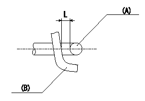
Adjustment of the V-FICD
1. Adjust the actuator rod to obtain L1.
2. Apply negative pressure P1 to the actuator and confirm the full stroke.
(A) actuator shaft
(B) Control lever
----------
L=1+1mm P1=-53.3kPa(-400mmHg)
----------
L=1+1mm
----------
L=1+1mm P1=-53.3kPa(-400mmHg)
----------
L=1+1mm
0000001901 POTENTIOMETER ADJUSTMENT
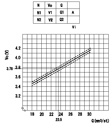
Adjustment of the potentiometer
Measure the injection quantity at pump speed N1 and control lever position a (lever, stopper clearance corresponding to L1). Install the potentiometer in accordance with the graph.
N:Pump speed
Vo:Output voltage
Q:Injection quantity
A:Adjusting point
Vi:Voltage
----------
N1=1100r/min a=20deg L1=6.6mm Vi=10V
----------
N1=1100r/min N2=800r/min V1=3.78+-0.03V V2=3.11+-0.03V Q1=23.5+-1mm3/st Q2=(25.0mm3/st) Vi=10V
----------
N1=1100r/min a=20deg L1=6.6mm Vi=10V
----------
N1=1100r/min N2=800r/min V1=3.78+-0.03V V2=3.11+-0.03V Q1=23.5+-1mm3/st Q2=(25.0mm3/st) Vi=10V
Information:
Recommended Procedure A. MISFIRING AND RUNNING ROUGHSee the chart, Misfiring and Running Rough. B. PROBLEM WITH VEHICLE or VEHICLE OPERATIONSee the chart, Problem With Vehicle or Vehicle Operation. C. LOW ENGINE RPM1. Governor Linkage Disconnect the governor linkage at the lever on the governor. Move the governor lever by hand until the linkage inside the governor is against the high idle stop. With the accelerator pedal all the way down, adjust the linkage so that the inside linkage is against the high idle stop. Some trucks are equipped with linkage which has spring force and some are equipped with a governor lever of the break over type. On engines with either of these, adjust the governor linkage .250 in. (6,35 mm) longer than necessary for the inside linkage to be against the high idle stop, this will keep tension on the spring at all times. For trucks with tilt cabs, do not make this check with the cab tilted.2. Governor High Idle Adjustment If the governor linkage moves the governor lever to the fully open position, check the high idle rpm with a good tachometer. If the high idle rpm is too low, turn the high idle adjustment screw counterclockwise until high idle rpm is correct. See the RACK SETTING INFORMATION for the correct high idle rpm. If high idle rpm can not be made correct with the high idle adjustment screw, there is a problem inside the governor. Disassemble the governor and check for damage to parts or the wrong parts installed in the governor. D. NOT ENOUGH AIR3. Inlet Restriction Air inlet restriction will cause low power and too much smoke when under load. Check for a restriction with a water manometer or a vacuum gauge (which measures in inches of water). Connect the gauge to the engine air inlet between the air cleaner and the engine. With gauge installed, run engine at full load rpm and check the restriction. Maximum restriction of the air inlet is 30 inches (762 mm) of water. If the indication is higher than the maximum permissible restriction, remove dirt from the filter element or install a new filter element and check the restriction again. If the indication is still too high, there must be a restriction in the inlet piping.4. Exhaust Restriction Make a visual inspection of the exhaust system and look for damage to piping or for a bad muffler. If no damage is found, you can also check the system by removing the exhaust pipes from the exhaust manifolds. With the exhaust pipes removed, start and run the engine to see if the problem is corrected. E. LOW QUALITY FUEL5. Water in Fuel Remove a small amount of fuel from the tank and check for water in the fuel. If there is water in the fuel, remove fuel from tank until it is free of water. Install a new fuel filter and fill the fuel tank with clean fuel. "Prime" (remove the air and/or low quality fuel
Have questions with 104740-1100?
Group cross 104740-1100 ZEXEL
Isuzu
104740-1100
8941323760
INJECTION-PUMP ASSEMBLY
C223T
C223T