Information injection-pump assembly
BOSCH
9 460 613 155
9460613155
ZEXEL
104740-0962
1047400962
MAZDA
WL8313800A
wl8313800a
Rating:
Components :
| 0. | INJECTION-PUMP ASSEMBLY | 104740-0962 |
| 1. | _ | |
| 2. | FUEL INJECTION PUMP | 104640-0962 |
| 3. | NUMBER PLATE | 146995-4100 |
| 4. | _ | |
| 5. | CAPSULE | |
| 6. | ADJUSTING DEVICE | 146679-4120 |
| 7. | NOZZLE AND HOLDER ASSY | 105148-1183 |
| 8. | Nozzle and Holder | PN40 13 H50C |
| 9. | Open Pre:MPa(Kqf/cm2) | 10.8{110} |
| 10. | NOZZLE-HOLDER | 105078-0111 |
| 11. | NOZZLE | 105007-1210 |
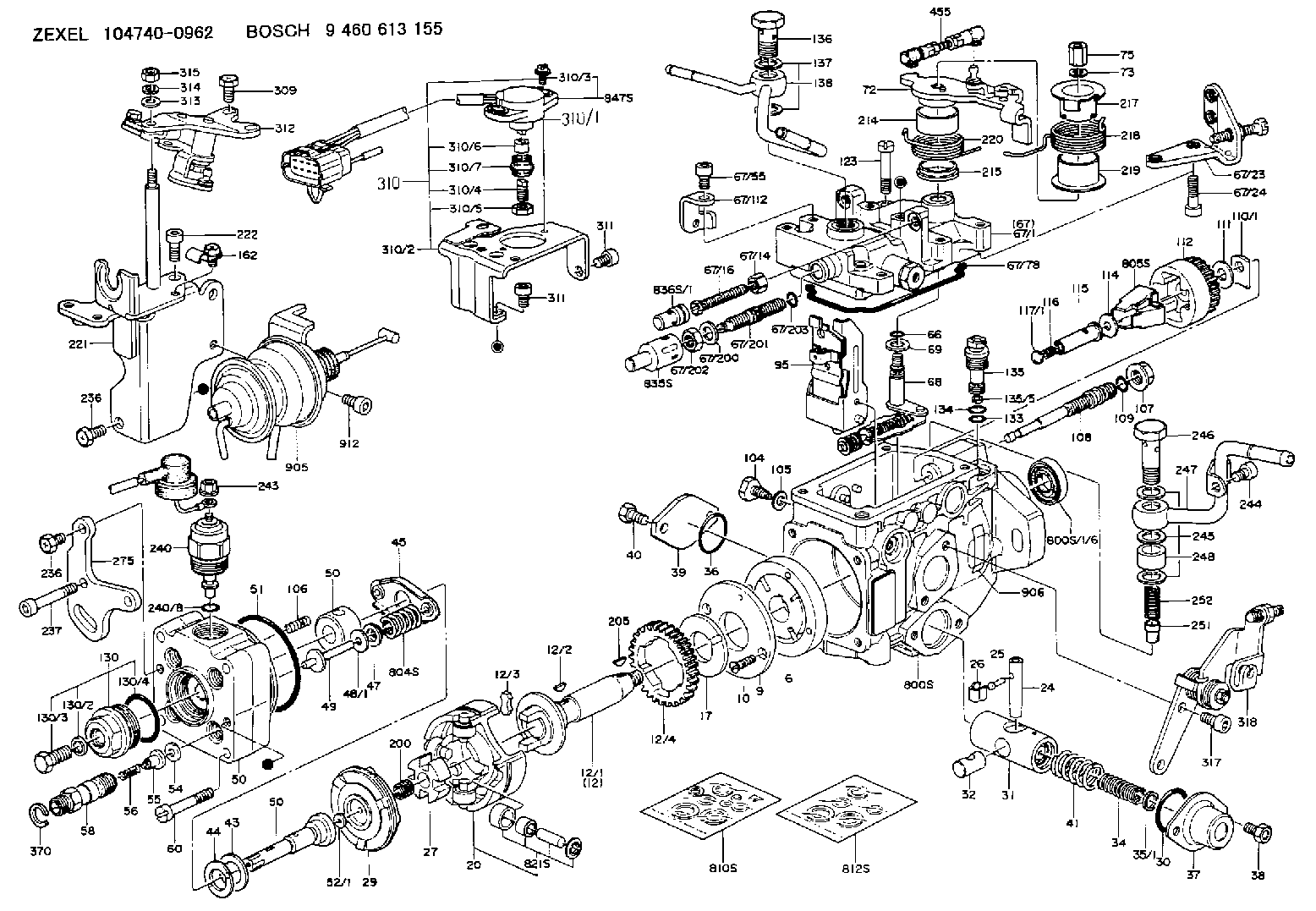
Scheme ###:
| 1/6. | [1] | 146601-0700 | PACKING RING |
| 6. | [1] | 146100-0720 | SUPPLY PUMP |
| 9. | [1] | 146103-0100 | COVER |
| 10. | [2] | 139104-0000 | FLAT-HEAD SCREW |
| 12. | [1] | 146200-0420 | DRIVE SHAFT |
| 12/1. | [1] | 146200-0400 | DRIVE SHAFT |
| 12/2. | [1] | 146201-0000 | WOODRUFF KEY |
| 12/3. | [2] | 146202-0100 | DAMPER |
| 12/4. | [1] | 146203-0000 | TOOTHED GEAR |
| 17. | [1] | 146204-0000 | PLAIN WASHER |
| 20. | [1] | 146210-5320 | ROLLER SET |
| 24. | [1] | 146303-0100 | BEARING PIN |
| 25. | [1] | 146304-0000 | BEARING PIN |
| 26. | [1] | 146305-0000 | CLAMPING BAND |
| 27. | [1] | 146205-0000 | SLOTTED WASHER |
| 29. | [1] | 146220-4720 | CAM PLATE |
| 30. | [1] | 146600-0800 | O-RING |
| 31. | [1] | 146311-8420 | PUMP PLUNGER |
| 32. | [1] | 146301-0000 | SLIDING PIECE |
| 34. | [1] | 146312-2900 | COMPRESSION SPRING |
| 34B. | [1] | 146312-2800 | COMPRESSION SPRING |
| 34C. | [1] | 146312-3000 | COMPRESSION SPRING |
| 35/1. | [1] | 146690-3200 | SHIM D11.5&9.4T0.1 |
| 35/1. | [1] | 146690-3300 | SHIM D11.5&9.4T0.2 |
| 35/1. | [1] | 146690-3400 | SHIM D11.5&9.4T0.25 |
| 35/1. | [1] | 146690-3500 | SHIM D11.5&9.4T1.0 |
| 35/1. | [1] | 146690-4100 | SHIM D11.5&9.4T2 |
| 35/1. | [1] | 146690-4200 | SHIM D11.5&9.4T0.5 |
| 35/1. | [1] | 146690-4300 | SHIM D11.5&9.4T0.75 |
| 36. | [1] | 146600-0800 | O-RING |
| 37. | [1] | 146310-4020 | COVER |
| 38. | [2] | 146620-5000 | BLEEDER SCREW |
| 39. | [1] | 146310-0100 | COVER |
| 40. | [2] | 146620-5000 | BLEEDER SCREW |
| 41. | [1] | 146312-3300 | COMPRESSION SPRING |
| 43. | [1] | 146230-0000 | SHIM |
| 44. | [1] | 146230-0100 | PLAIN WASHER |
| 45. | [1] | 146231-0001 | SLOTTED WASHER |
| 47. | [2] | 146233-0000 | SLOTTED WASHER |
| 48/1. | [1] | 146603-0000 | SHIM D17.0&5.2T0.50 |
| 48/1. | [1] | 146603-0100 | SHIM D17.0&5.2T0.80 |
| 48/1. | [1] | 146603-0200 | SHIM D17.0&5.2T1.00 |
| 48/1. | [1] | 146603-0300 | SHIM D17.0&5.2T1.20 |
| 48/1. | [1] | 146603-0400 | SHIM D17.0&5.2T1.50 |
| 48/1. | [1] | 146603-0500 | SHIM D17.0&5.2T1.80 |
| 48/1. | [1] | 146603-0600 | SHIM D17.0&5.2T2.00 |
| 48/1. | [1] | 146690-1400 | SHIM D17&5.2T0.9 |
| 48/1. | [1] | 146690-1500 | SHIM D17&5.2T1.1 |
| 48/1. | [1] | 146690-1600 | SHIM D17&5.2T1.3 |
| 48/1. | [1] | 146690-1700 | SHIM D17&5.2T1.4 |
| 48/1. | [1] | 146690-1800 | SHIM D17&5.2T1.6 |
| 48/1. | [1] | 146690-1900 | SHIM D17&5.2T1.7 |
| 48/1. | [1] | 146690-5800 | SHIM D17&5.2T2.1 |
| 48/1. | [1] | 146690-5900 | SHIM D17&5.2T2.2 |
| 48/1. | [1] | 146690-6000 | SHIM D17&5.2T2.3 |
| 48/1. | [1] | 146690-6100 | SHIM D17&5.2T2.4 |
| 48/1. | [1] | 146690-6200 | SHIM D17&5.2T2.5 |
| 48/1. | [1] | 146690-6300 | SHIM D17&5.2T2.6 |
| 48/1. | [1] | 146690-6400 | SHIM D17&5.2T2.7 |
| 48/1. | [1] | 146690-6500 | SHIM D17&5.2T2.8 |
| 48/1. | [1] | 146690-6600 | SHIM D17&5.2T2.9 |
| 48/1. | [1] | 146690-6700 | SHIM D17&5.2T3.0 |
| 48/1. | [1] | 146690-6800 | SHIM D17&5.2T3.1 |
| 48/1. | [1] | 146690-6900 | SHIM D17&5.2T3.2 |
| 48/1. | [1] | 146690-7000 | SHIM D17&5.2T3.3 |
| 48/1. | [1] | 146690-7100 | SHIM D17&5.2T3.4 |
| 48/1. | [1] | 146690-7200 | SHIM D17&5.2T0.4 |
| 48/1. | [1] | 146690-7300 | SHIM D17&5.2T0.6 |
| 48/1. | [1] | 146690-7400 | SHIM D17&5.2T0.7 |
| 48/1. | [1] | 146690-7500 | SHIM D17&5.2T1.9 |
| 48/1. | [1] | 146690-7800 | SHIM D17&5.2T0.2 |
| 49. | [2] | 146234-0600 | GUIDE PIN |
| 50. | [1] | 146403-6820 | HYDRAULIC HEAD |
| 50. | [1] | 146403-6820 | HYDRAULIC HEAD |
| 50. | [1] | 146403-6820 | HYDRAULIC HEAD |
| 51. | [1] | 146600-0000 | O-RING |
| 52/1. | [1] | 146420-0000 | SHIM D9.5&3.0T1.90 |
| 52/1. | [1] | 146420-0100 | SHIM D9.5&3.0T1.92 |
| 52/1. | [1] | 146420-0200 | SHIM D9.5&3.0T1.94 |
| 52/1. | [1] | 146420-0300 | SHIM D9.5&3.0T1.96 |
| 52/1. | [1] | 146420-0400 | SHIM D9.5&3.0T1.98 |
| 52/1. | [1] | 146420-0500 | SHIM D9.5&3.0T2.00 |
| 52/1. | [1] | 146420-0600 | SHIM D9.5&3.0T2.02 |
| 52/1. | [1] | 146420-0700 | SHIM D9.5&3.0T2.04 |
| 52/1. | [1] | 146420-0800 | SHIM D9.5&3.0T2.06 |
| 52/1. | [1] | 146420-0900 | SHIM D9.5&3.0T2.08 |
| 52/1. | [1] | 146420-1000 | SHIM D9.5&3.0T2.10 |
| 52/1. | [1] | 146420-1100 | SHIM D9.5&3.0T2.12 |
| 52/1. | [1] | 146420-1200 | SHIM D9.5&3.0T2.14 |
| 52/1. | [1] | 146420-1300 | SHIM D9.5&3.0T2.16 |
| 52/1. | [1] | 146420-1400 | SHIM D9.5&3.0T2.18 |
| 52/1. | [1] | 146420-1500 | SHIM D9.5&3.0T2.20 |
| 52/1. | [1] | 146420-1600 | SHIM D9.5&3.0T2.22 |
| 52/1. | [1] | 146420-1700 | SHIM D9.5&3.0T2.24 |
| 52/1. | [1] | 146420-1800 | SHIM D9.5&3.0T2.26 |
| 52/1. | [1] | 146420-1900 | SHIM D9.5&3.0T2.28 |
| 52/1. | [1] | 146420-2000 | SHIM D9.5&3.0T2.30 |
| 52/1. | [1] | 146420-2100 | SHIM D9.5&3.0T2.32 |
| 52/1. | [1] | 146420-2200 | SHIM D9.5&3.0T2.34 |
| 52/1. | [1] | 146420-2300 | SHIM D9.5&3.0T2.36 |
| 52/1. | [1] | 146420-2400 | SHIM D9.5&3.0T2.38 |
| 52/1. | [1] | 146420-2500 | SHIM D9.5&3.0T2.40 |
| 52/1. | [1] | 146420-2600 | SHIM D9.5&3.0T2.42 |
| 52/1. | [1] | 146420-2700 | SHIM D9.5&3.0T2.44 |
| 52/1. | [1] | 146420-2800 | SHIM D9.5&3.0T2.46 |
| 52/1. | [1] | 146420-2900 | SHIM D9.5&3.0T2.48 |
| 52/1. | [1] | 146420-3000 | SHIM D9.5&3.0T2.50 |
| 52/1. | [1] | 146420-3100 | SHIM D9.5&3.0T2.52 |
| 52/1. | [1] | 146420-3200 | SHIM D9.5&3.0T2.54 |
| 52/1. | [1] | 146420-3300 | SHIM D9.5&3.0T2.56 |
| 52/1. | [1] | 146420-3400 | SHIM D9.5&3.0T2.58 |
| 52/1. | [1] | 146420-3500 | SHIM D9.5&3.0T2.60 |
| 52/1. | [1] | 146420-3600 | SHIM D9.5&3.0T2.62 |
| 52/1. | [1] | 146420-3700 | SHIM D9.5&3.0T2.64 |
| 52/1. | [1] | 146420-3800 | SHIM D9.5&3.0T2.66 |
| 52/1. | [1] | 146420-3900 | SHIM D9.5&3.0T2.68 |
| 52/1. | [1] | 146420-4000 | SHIM D9.5&3.0T2.70 |
| 52/1. | [1] | 146420-4100 | SHIM D9.5&3.0T2.72 |
| 52/1. | [1] | 146420-4200 | SHIM D9.5&3.0T2.74 |
| 52/1. | [1] | 146420-4300 | SHIM D9.5&3.0T2.76 |
| 52/1. | [1] | 146420-4400 | SHIM D9.5&3.0T2.78 |
| 52/1. | [1] | 146420-4500 | SHIM D9.5&3.0T2.80 |
| 52/1. | [1] | 146420-4600 | SHIM D9.5&3.0T2.82 |
| 52/1. | [1] | 146420-4700 | SHIM D9.5&3.0T2.84 |
| 52/1. | [1] | 146420-4800 | SHIM D9.5&3.0T2.86 |
| 52/1. | [1] | 146420-4900 | SHIM D9.5&3.0T2.88 |
| 52/1. | [1] | 146420-5000 | SHIM D9.5&3.0T2.90 |
| 52/1. | [1] | 146420-5100 | SHIM D9.5&3.0T1.74 |
| 52/1. | [1] | 146420-5200 | SHIM D9.5&3.0T1.76 |
| 52/1. | [1] | 146420-5300 | SHIM D9.5&3.0T1.78 |
| 52/1. | [1] | 146420-5400 | SHIM D9.5&3.0T1.80 |
| 52/1. | [1] | 146420-5500 | SHIM D9.5&3.0T1.82 |
| 52/1. | [1] | 146420-5600 | SHIM D9.5&3.0T1.84 |
| 52/1. | [1] | 146420-5700 | SHIM D9.5&3.0T1.86 |
| 52/1. | [1] | 146420-5800 | SHIM D9.5&3.0T1.88 |
| 54. | [4] | 146433-0100 | GASKET D12&6.4T1.00 |
| 55. | [4] | 146430-7420 | DELIVERY-VALVE ASSEMBLY |
| 56. | [4] | 146432-0000 | COMPRESSION SPRING |
| 58. | [4] | 146440-0220 | FITTING |
| 60. | [3] | 139106-0100 | FLAT-HEAD SCREW |
| 66. | [1] | 146600-0100 | O-RING |
| 67. | [1] | 146504-1120 | GOVERNOR COVER |
| 67/1. | [1] | 146806-4020 | GOVERNOR COVER |
| 67/14. | [1] | 146621-1700 | UNION NUT |
| 67/16. | [1] | 146526-2800 | BLEEDER SCREW |
| 67/23. | [1] | 146934-3220 | BRACKET |
| 67/24. | [2] | 010206-2240 | HEX-SOCKET-HEAD CAP SCREW |
| 67/55. | [1] | 010206-1040 | HEX-SOCKET-HEAD CAP SCREW |
| 67/78. | [1] | 146600-4400 | SEAL RING |
| 67/112. | [1] | 146934-6000 | BRACKET |
| 67/200. | [1] | 139308-0300 | PLAIN WASHER |
| 67/201. | [1] | 146545-4100 | THREADED PIN |
| 67/201B. | [1] | 146545-4200 | THREADED PIN |
| 67/201C. | [1] | 146545-4300 | THREADED PIN |
| 67/202. | [1] | 139208-0900 | UNION NUT |
| 67/203. | [1] | 146600-1200 | O-RING |
| 68. | [1] | 146810-6920 | CONTROL SHAFT |
| 69. | [1] | 139310-0200 | PLAIN WASHER |
| 72. | [1] | 146832-0321 | CONTROL LEVER |
| 72B. | [1] | 146832-0421 | CONTROL LEVER |
| 72C. | [1] | 146832-1920 | CONTROL LEVER |
| 72D. | [1] | 146832-2020 | CONTROL LEVER |
| 73. | [1] | 014110-6440 | LOCKING WASHER |
| 75. | [1] | 146621-0700 | UNION NUT |
| 95. | [1] | 146865-6720 | FULCRUM LEVER |
| 104. | [2] | 146568-0000 | SLOTTED SPRING PIN |
| 105. | [2] | 026508-1140 | GASKET D11.4&8.2T1 |
| 106. | [2] | 146588-0500 | COILED SPRING |
| 107. | [1] | 146569-0300 | UNION NUT |
| 108. | [1] | 146570-0420 | GOVERNOR SHAFT |
| 109. | [1] | 146600-0400 | O-RING |
| 110/1. | [1] | 146571-0000 | SHIM D20.2&8.3T1.05 |
| 110/1. | [1] | 146571-0100 | SHIM D20.2&8.3T1.25 |
| 110/1. | [1] | 146571-0200 | SHIM D20.2&8.3T1.45 |
| 110/1. | [1] | 146571-0300 | SHIM D20.2&8.3T1.65 |
| 110/1. | [1] | 146571-0400 | SHIM D20.2&8.3T1.85 |
| 110/1. | [1] | 146571-0500 | SHIM D20.2&8.3T1.15 |
| 110/1. | [1] | 146571-0600 | SHIM D20.2&8.3T1.35 |
| 110/1. | [1] | 146571-0700 | SHIM D20.2&8.3T1.55 |
| 110/1. | [1] | 146571-0800 | SHIM D20.2&8.3T1.75 |
| 111. | [1] | 146602-0600 | PLAIN WASHER D20&8.4T1.40 |
| 112. | [1] | 146572-0020 | FLYWEIGHT ASSEMBLY |
| 114. | [1] | 146602-0500 | PLAIN WASHER D17&6.4T1.60 |
| 115. | [1] | 146975-6700 | SLIDING SLEEVE |
| 116. | [1] | 146576-0200 | CAP |
| 117/1. | [1] | 146577-1800 | PLUG L2.10 |
| 117/1. | [1] | 146577-1900 | PLUG L2.30 |
| 117/1. | [1] | 146577-2000 | PLUG L2.50 |
| 117/1. | [1] | 146577-2100 | PLUG L2.70 |
| 117/1. | [1] | 146577-2200 | PLUG L2.90 |
| 117/1. | [1] | 146577-2300 | PLUG L3.10 |
| 117/1. | [1] | 146577-2400 | PLUG L3.30 |
| 117/1. | [1] | 146577-2500 | PLUG L3.50 |
| 117/1. | [1] | 146577-2600 | PLUG L3.70 |
| 117/1. | [1] | 146577-2700 | PLUG L3.90 |
| 117/1. | [1] | 146577-2800 | PLUG L4.10 |
| 117/1. | [1] | 146577-2900 | PLUG L4.30 |
| 117/1. | [1] | 146577-3000 | PLUG L4.50 |
| 117/1. | [1] | 146577-3100 | PLUG L4.70 |
| 117/1. | [1] | 146577-3200 | PLUG L4.90 |
| 117/1. | [1] | 146577-3300 | PLUG L5.10 |
| 117/1. | [1] | 146577-6700 | PLUG L2.2 |
| 117/1. | [1] | 146577-6800 | PLUG L2.4 |
| 117/1. | [1] | 146577-6900 | PLUG L2.6 |
| 117/1. | [1] | 146577-7000 | PLUG L2.8 |
| 117/1. | [1] | 146577-7100 | PLUG L3.0 |
| 117/1. | [1] | 146577-7200 | PLUG L3.2 |
| 117/1. | [1] | 146577-7300 | PLUG L3.4 |
| 117/1. | [1] | 146577-7400 | PLUG L3.6 |
| 117/1. | [1] | 146577-7500 | PLUG L3.8 |
| 117/1. | [1] | 146577-7600 | PLUG L4.0 |
| 117/1. | [1] | 146577-7700 | PLUG L4.2 |
| 117/1. | [1] | 146577-7800 | PLUG L4.4 |
| 117/1. | [1] | 146577-7900 | PLUG L4.6 |
| 117/1. | [1] | 146577-8000 | PLUG L4.8 |
| 117/1. | [1] | 146577-8100 | PLUG L5.0 |
| 117/1. | [1] | 146877-0000 | PLUG L5.2 |
| 117/1. | [1] | 146877-0100 | PLUG L5.3 |
| 117/1. | [1] | 146877-0200 | PLUG L5.4 |
| 117/1. | [1] | 146877-0300 | PLUG L5.5 |
| 117/1. | [1] | 146877-4700 | PLUG |
| 117/1. | [1] | 146877-4800 | PLUG |
| 117/1. | [1] | 146877-4900 | PLUG |
| 117/1. | [1] | 146877-5000 | PLUG |
| 123. | [4] | 139106-0200 | FLAT-HEAD SCREW |
| 130. | [1] | 146421-0020 | CAPSULE |
| 130/2. | [1] | 026508-1140 | GASKET D11.4&8.2T1 |
| 130/3. | [1] | 146422-0000 | BLEEDER SCREW |
| 130/4. | [1] | 146600-0500 | O-RING |
| 133. | [1] | 146600-0600 | O-RING |
| 134. | [1] | 146600-0700 | O-RING |
| 135. | [1] | 146110-0920 | CONTROL VALVE |
| 135/5. | [1] | 146114-0000 | SPRING WASHER |
| 136. | [1] | 146120-0020 | OVER FLOW VALVE |
| 137. | [2] | 139512-0500 | GASKET |
| 138. | [1] | 146669-6720 | INLET UNION |
| 162. | [1] | 146625-8020 | PLATE |
| 200. | [1] | 146206-0100 | COILED SPRING |
| 205. | [1] | 146201-0100 | WOODRUFF KEY |
| 214. | [1] | 146542-1400 | BUSHING |
| 215. | [1] | 146542-1500 | BUSHING |
| 217. | [1] | 146542-2600 | SLOTTED WASHER |
| 218. | [1] | 146592-8400 | COILED SPRING |
| 219. | [1] | 146541-3000 | BUSHING |
| 220. | [1] | 146592-8500 | COILED SPRING |
| 221. | [1] | 146934-9320 | BRACKET |
| 222. | [1] | 010206-1440 | HEX-SOCKET-HEAD CAP SCREW M6P1L14 |
| 236. | [3] | 139006-4800 | BLEEDER SCREW |
| 236. | [3] | 139006-4800 | BLEEDER SCREW |
| 237. | [1] | 146620-0200 | HEX-SOCKET-HEAD CAP SCREW |
| 240. | [1] | 146650-4320 | PULLING ELECTROMAGNET |
| 240/8. | [1] | 146600-1700 | O-RING |
| 243. | [1] | 146621-1000 | UNION NUT |
| 244. | [1] | 010206-1040 | HEX-SOCKET-HEAD CAP SCREW |
| 245. | [3] | 139512-0500 | GASKET |
| 246. | [1] | 146125-0600 | EYE BOLT |
| 247. | [1] | 146667-0820 | INLET UNION |
| 248. | [1] | 146614-0200 | SPACER BUSHING |
| 251. | [1] | 146125-0101 | FILTER |
| 252. | [1] | 146125-0200 | COILED SPRING |
| 275. | [1] | 146932-8000 | BRACKET |
| 309. | [2] | 139006-5700 | BLEEDER SCREW |
| 310. | [1] | 146685-2321 | POTENTCIOMETER |
| 310/1. | [1] | 146685-2310 | POTENTCIOMETER |
| 310/2. | [1] | 146934-6121 | BRACKET |
| 310/3. | [2] | 139104-0400 | FLAT-HEAD SCREW |
| 310/4. | [1] | 146620-2900 | FLAT-HEAD SCREW |
| 310/5. | [1] | 146621-0500 | UNION NUT |
| 310/6. | [1] | 146614-2300 | JOINT CONNECTION |
| 310/7. | [1] | 146661-0401 | BOOT |
| 311. | [3] | 010206-1040 | HEX-SOCKET-HEAD CAP SCREW |
| 311. | [3] | 010206-1040 | HEX-SOCKET-HEAD CAP SCREW |
| 312. | [1] | 146934-9420 | BRACKET |
| 313. | [1] | 014010-5140 | PLAIN WASHER D12&5.5T0.8 |
| 314. | [1] | 014110-5440 | LOCKING WASHER |
| 315. | [1] | 013020-5240 | UNION NUT M5P0.8H4 |
| 317. | [2] | 010206-1040 | HEX-SOCKET-HEAD CAP SCREW |
| 318. | [1] | 146932-8320 | BRACKET |
| 370. | [1] | 146663-2720 | SPACER RING |
| 455. | [1] | 146849-3220 | RACK |
| 800S. | [1] | 146018-8420 | PUMP HOUSING |
| 800S/1/6. | [1] | 146601-0700 | PACKING RING |
| 804S. | [1] | 146232-0720 | COMPRESSION SPRING |
| 805S. | [1] | 146574-0120 | PARTS SET |
| 810S. | [1] | 146600-2420 | REPAIR SET |
| 812S. | [1] | 146600-1920 | PARTS SET |
| 821S. | [1] | 146210-5820 | ROLLER SET |
| 835S. | [1] | 146598-1000 | CAP |
| 836S/1. | [1] | 146598-0600 | CAP L18 |
| 836S/1. | [1] | 146598-0700 | CAP L21 |
| 836S/1. | [1] | 146598-0800 | CAP L24 |
| 836S/1. | [1] | 146598-0900 | CAP L27 |
| 847S. | [1] | 146685-2410 | POTENTCIOMETER |
| 905. | [1] | 146679-4120 | ACTUATOR |
| 906. | [1] | 146995-4100 | NAMEPLATE |
| 912. | [2] | 010206-1440 | HEX-SOCKET-HEAD CAP SCREW M6P1L14 |
Include in #2:
104740-0962
as INJECTION-PUMP ASSEMBLY
Cross reference number
BOSCH
9 460 613 155
9460613155
ZEXEL
104740-0962
1047400962
MAZDA
WL8313800A
wl8313800a
Zexel num
Bosch num
Firm num
Name
Calibration Data:
Adjustment conditions
Test oil
1404 Test oil ISO4113orSAEJ967d
1404 Test oil ISO4113orSAEJ967d
Test oil temperature
degC
45
45
50
Nozzle
105780-0060
Bosch type code
NP-DN0SD1510
Nozzle holder
105780-2150
Opening pressure
MPa
13
13
13.3
Opening pressure
kgf/cm2
133
133
136
Injection pipe
157805-7320
Injection pipe
Inside diameter - outside diameter - length (mm) mm 2-6-450
Inside diameter - outside diameter - length (mm) mm 2-6-450
Joint assembly
157641-4720
Tube assembly
157641-4020
Transfer pump pressure
kPa
20
20
20
Transfer pump pressure
kgf/cm2
0.2
0.2
0.2
Direction of rotation (viewed from drive side)
Left L
Left L
Injection timing adjustment
Pump speed
r/min
1250
1250
1250
Average injection quantity
mm3/st.
48.7
48.2
49.2
Difference in delivery
mm3/st.
4
Basic
*
Oil temperature
degC
50
48
52
Injection timing adjustment_02
Pump speed
r/min
500
500
500
Average injection quantity
mm3/st.
44.8
41.8
47.8
Oil temperature
degC
48
46
50
Injection timing adjustment_03
Pump speed
r/min
1250
1250
1250
Average injection quantity
mm3/st.
48.7
47.7
49.7
Difference in delivery
mm3/st.
4.5
Basic
*
Oil temperature
degC
50
48
52
Injection timing adjustment_04
Pump speed
r/min
2100
2100
2100
Average injection quantity
mm3/st.
44.3
40.8
47.8
Oil temperature
degC
52
50
54
Injection quantity adjustment
Pump speed
r/min
2450
2450
2450
Average injection quantity
mm3/st.
15.7
12.7
18.7
Difference in delivery
mm3/st.
5
Basic
*
Oil temperature
degC
55
52
58
Injection quantity adjustment_02
Pump speed
r/min
2450
2450
2450
Average injection quantity
mm3/st.
15.7
5.7
25.7
Difference in delivery
mm3/st.
5.5
Basic
*
Oil temperature
degC
55
52
58
Injection quantity adjustment_03
Pump speed
r/min
2800
2800
2800
Average injection quantity
mm3/st.
5
Oil temperature
degC
55
52
58
Governor adjustment
Pump speed
r/min
360
360
360
Average injection quantity
mm3/st.
9
8
10
Difference in delivery
mm3/st.
1.7
Basic
*
Oil temperature
degC
48
46
50
Governor adjustment_02
Pump speed
r/min
360
360
360
Average injection quantity
mm3/st.
9
7.5
10.5
Difference in delivery
mm3/st.
2.2
Basic
*
Oil temperature
degC
48
46
50
Boost compensator adjustment
Pump speed
r/min
400
400
400
Average injection quantity
mm3/st.
17
15
19
Difference in delivery
mm3/st.
3
Oil temperature
degC
48
46
50
Timer adjustment
Pump speed
r/min
150
150
150
Average injection quantity
mm3/st.
70
55
90
Basic
*
Oil temperature
degC
48
46
50
Timer adjustment_02
Pump speed
r/min
150
150
150
Average injection quantity
mm3/st.
70
50
90
Oil temperature
degC
48
46
50
Speed control lever angle
Pump speed
r/min
360
360
360
Average injection quantity
mm3/st.
0
0
0
Oil temperature
degC
48
46
50
Remarks
Magnet OFF
Magnet OFF
0000000901
Pump speed
r/min
1250
1250
1250
Overflow quantity
cm3/min
420
290
550
Oil temperature
degC
50
48
52
Stop lever angle
Pump speed
r/min
1250
1250
1250
Pressure
kPa
569
540
598
Pressure
kgf/cm2
5.8
5.5
6.1
Basic
*
Oil temperature
degC
50
48
52
Stop lever angle_02
Pump speed
r/min
1250
1250
1250
Pressure
kPa
569
530
608
Pressure
kgf/cm2
5.8
5.4
6.2
Basic
*
Oil temperature
degC
50
48
52
0000001101
Pump speed
r/min
1250
1250
1250
Timer stroke
mm
5.7
5.5
5.9
Basic
*
Oil temperature
degC
50
48
52
_02
Pump speed
r/min
500
500
500
Timer stroke
mm
1.8
1
2.6
Oil temperature
degC
48
46
50
_03
Pump speed
r/min
1250
1250
1250
Timer stroke
mm
5.7
5.3
6.1
Basic
*
Oil temperature
degC
50
48
52
_04
Pump speed
r/min
2000
2000
2000
Timer stroke
mm
9.2
8.4
10
Oil temperature
degC
50
48
52
0000001201
Max. applied voltage
V
8
8
8
Test voltage
V
13
12
14
0000001401
Pump speed
r/min
1250
1250
1250
Average injection quantity
mm3/st.
33.6
33.1
34.1
Timer stroke TA
mm
5.2
5
5.4
Timer stroke variation dT
mm
0.5
0.5
0.5
Basic
*
Oil temperature
degC
50
48
52
_02
Pump speed
r/min
1250
1250
1250
Average injection quantity
mm3/st.
33.6
32.6
34.6
Timer stroke TA
mm
5.2
4.8
5.6
Timer stroke variation dT
mm
0.5
0.5
0.5
Basic
*
Oil temperature
degC
50
48
52
_03
Pump speed
r/min
1250
1250
1250
Average injection quantity
mm3/st.
25
23.5
26.5
Timer stroke TA
mm
4.1
3.5
4.7
Timer stroke variation dT
mm
1.6
1.6
1.6
Oil temperature
degC
50
48
52
Timing setting
K dimension
mm
3.3
3.2
3.4
KF dimension
mm
6.01
5.91
6.11
MS dimension
mm
0.9
0.8
1
Pre-stroke
mm
0.03
0.01
0.05
Control lever angle alpha
deg.
12.5
8.5
16.5
Control lever angle beta
deg.
40
37
43
Test data Ex:
0000001801 CONTROL STANDARD AT IDLING
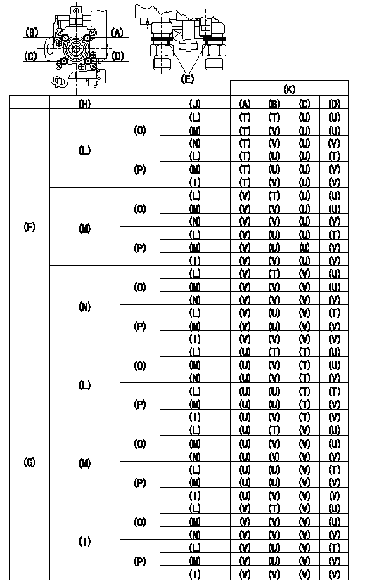
Standards for idle difference in delivery control
After idle adjustment, measure the idle injection quantities of (A) to (D).
Install the colored rings to the delivery valve holders (A) to (D) in accordance with the table.
(A): A cylinder (B) :B cylinder (C) : C cylinder (D): D cylinder
(E): Collar ring
(F): (A) >= (C)
(G): (C) > (A)
(H): (A) - (C) or (C) - (A)
(I): 0.2, 0.1(mm3/st)
(J): (B) - (D) or (D) - (B)
(K): Ring color
(L): At least 0.6 mm3/st
(M): 0.3, 0.4, 0.5 (mm3/st)
(N): 0.2, 0.1, 0.0 (mm3/st)
(O): (B) >= (D)
(P): (D) > (B)
(T): Yellow
(U): White
(V): Red
----------
----------
----------
----------
0000001901 POTENTIOMETER ADJUSTMENT
Confirm potentiometer output voltage
Control lever (1) Full position: V1 (Adjusting point)
(2)Idle position: V2 (checking point)
----------
V1=8.40+-0.03V V2=1.73+-0.7V
----------
----------
V1=8.40+-0.03V V2=1.73+-0.7V
----------
0000002001 A/T PLATE ADJUSTMENT
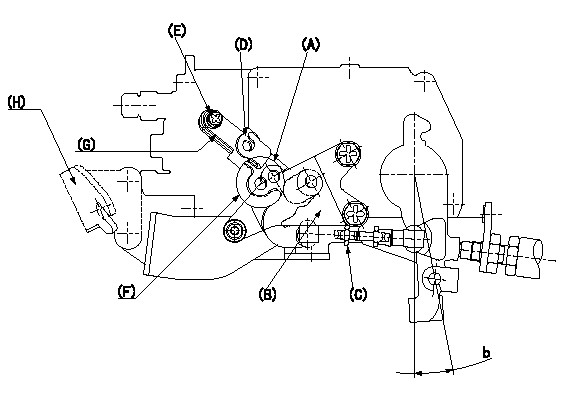
A/T link lever initial position setting
With the control lever at position a, adjust the length of connecting rod (C) so that the pin L1 can pass through the A/T link lever (A) and the bracket (B) at X. Then fix at torque T1.
A/T wire stroke adjustment
Mount the A/T wire stroke measuring apparatus and the mounting jig Y (bracket).
Slide the plate (D) so that the stroke becomes L2 and fix the bolt (E) to torque T2.
Remove jigs after adjustment.
(A): A/T link lever
(B): Bracket
(C): Rod
(D): Plate
(E): Bolt
(F): X
(G): Marking line
(H): Jig Y
----------
a=0deg L1=Dia.5.8-0.2mm L2=30+-2mm T1=2.5~2.9N-m(0.25~0.31kgf-m) T2=3.4~4.9N-m(0.35~0.5kgf-m)
----------
b=(12.5deg)
----------
a=0deg L1=Dia.5.8-0.2mm L2=30+-2mm T1=2.5~2.9N-m(0.25~0.31kgf-m) T2=3.4~4.9N-m(0.35~0.5kgf-m)
----------
b=(12.5deg)
0000002101 WIRE
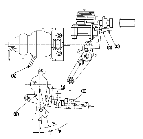
(1)Confirmation of the wire length:
Accelerator wire: Idle-full stroke: L1
(2)Confirmation on the idle SW
Confirm that the switch is ON at the idle lever position.
(3)Adjustment of the double stage actuator:
1. Apply negative pressure P1 to the actuator through the negative pressure suction inlet.
2. Under the conditions in 1. above, adjust using screw (C) so that the control lever () position is angle a [clearance L2+-0.5mm from idle switch (E)], and fix using the nut (D). (Tightening torque T)
b:Angle alpha
----------
L1=34.1+-3.5mm L2=3.3mm P1=-66.6kPa(-500mmHg) T=6~9N-m(0.6~0.9kgf-m) a=8.0deg b=12.5deg
----------
L2=(3.3mm) a=8.0deg b=12.5deg
----------
L1=34.1+-3.5mm L2=3.3mm P1=-66.6kPa(-500mmHg) T=6~9N-m(0.6~0.9kgf-m) a=8.0deg b=12.5deg
----------
L2=(3.3mm) a=8.0deg b=12.5deg
Information:
2. Remove "V" clamp (3). Remove the cartridge housing (5) from the turbine housing (4). 3. Install tool (C) in tool (B) and put the cartridge assembly in tool (C) as shown. Use tool (D) to remove the nut that holds compressor wheel (6).
When the nut is loosened, do not put a side force on the shaft.
The oil used to heat the compressor wheel must have a flash point (the temperature at which the oil will burn) above 400°F (204°C).
4. Install tool (H) on tool (E). Heat tool (E) to a temperature of 350°F (177°C). Install the cartridge assembly on tool (H) so that only the compressor wheel is in the oil. Heat the compressor wheel for no more than 10 minutes.
Do not let the turbine wheel hit the bottom of the press.
5. Install tool (H) on tool (G). Put the cartridge assembly in tool (H) as shown. Remove compressor wheel (6) with an arbor press and tool (F). Step 5 must be done before the compressor wheel becomes cooler. 6. Put the turbine wheel in tool (C). Remove seal ring (8) and shroud (7) from the shaft. 7. Bend the tabs of the locks from bolts (10) and remove the bolts and locks.8. Remove backplate assembly (11) from the cartridge housing. Remove spacer (9) from backplate assembly (11). Remove the seal rings from spacer (9).9. Remove the collar from behind backplate assembly (11). 10. Remove thrust bearing (13) and O-ring seal (12) from the cartridge housing. 11. Remove top bearing (14) and the washer from the cartridge housing. Put a long dye mark on the top face of bearing (14). 12. Use tool (J) and remove the two rings that hold top and bottom bearings in position. Remove the bottom bearing and washer. Put a short dye mark on the bearing. The dye marks are used for identification of the bearings when they are installed.13. Use tool (J) and remove the last ring that holds the bottom bearing in position from the cartridge housing.14. Check all the parts of the turbocharger for damage. If the parts have damage, use new parts for replacement. See SPECIAL INSTRUCTION FORM NO. SMHS6854 for TURBOCHARGER RECONDITIONING. Also see GUIDELINE FOR REUSABLE PARTS FORM NO. SEBF8018.Assemble Turbocharger (Airesearch TV81)
1. Make sure that all of the oil passages in the turbocharger cartridge housing are clean and free of dirt and foreign material.2. Put clean engine oil on all parts of the cartridge assembly.
Rings (1), (4) and (5) must be installed with the round edge of the rings toward the bearings.
3. Install ring (4) in the cartridge housing with tool (A).4. Install washer (3) and bearing (2) in the cartridge housing. Make sure the short dye mark on bearing (2) is up. 5. Install rings (1) and (5) in the cartridge housing with tool (A). Put 6V2055 High Vacuum Grease in the groove for seal ring (7) at assembly to one half or more of the depth of the groove all the way around.6.