Information injection-pump assembly
ZEXEL
104740-0940
1047400940

Rating:
Cross reference number
ZEXEL
104740-0940
1047400940
Zexel num
Bosch num
Firm num
Name
104740-0940
INJECTION-PUMP ASSEMBLY
Calibration Data:
Adjustment conditions
Test oil
1404 Test oil ISO4113orSAEJ967d
1404 Test oil ISO4113orSAEJ967d
Test oil temperature
degC
45
45
50
Nozzle
105780-0060
Bosch type code
NP-DN0SD1510
Nozzle holder
105780-2150
Opening pressure
MPa
13
13
13.3
Opening pressure
kgf/cm2
133
133
136
Injection pipe
157805-7320
Injection pipe
Inside diameter - outside diameter - length (mm) mm 2-6-450
Inside diameter - outside diameter - length (mm) mm 2-6-450
Joint assembly
157641-4720
Tube assembly
157641-4020
Transfer pump pressure
kPa
20
20
20
Transfer pump pressure
kgf/cm2
0.2
0.2
0.2
Direction of rotation (viewed from drive side)
Left L
Left L
Injection timing adjustment
Pump speed
r/min
1250
1250
1250
Average injection quantity
mm3/st.
50.2
49.7
50.7
Difference in delivery
mm3/st.
4
Basic
*
Oil temperature
degC
50
48
52
Injection timing adjustment_02
Pump speed
r/min
500
500
500
Average injection quantity
mm3/st.
45.9
42.9
48.9
Oil temperature
degC
48
46
50
Injection timing adjustment_03
Pump speed
r/min
1250
1250
1250
Average injection quantity
mm3/st.
50.2
49.2
51.2
Difference in delivery
mm3/st.
4.5
Basic
*
Oil temperature
degC
50
48
52
Injection timing adjustment_04
Pump speed
r/min
2100
2100
2100
Average injection quantity
mm3/st.
44.8
41.3
48.3
Oil temperature
degC
52
50
54
Injection quantity adjustment
Pump speed
r/min
2450
2450
2450
Average injection quantity
mm3/st.
15.7
12.7
18.7
Difference in delivery
mm3/st.
5
Basic
*
Oil temperature
degC
55
52
58
Injection quantity adjustment_02
Pump speed
r/min
2800
2800
2800
Average injection quantity
mm3/st.
5
Oil temperature
degC
55
52
58
Injection quantity adjustment_03
Pump speed
r/min
2450
2450
2450
Average injection quantity
mm3/st.
15.7
5.7
25.7
Difference in delivery
mm3/st.
5.5
Basic
*
Oil temperature
degC
55
52
58
Governor adjustment
Pump speed
r/min
360
360
360
Average injection quantity
mm3/st.
9
8
10
Difference in delivery
mm3/st.
1.7
Basic
*
Oil temperature
degC
48
46
50
Governor adjustment_02
Pump speed
r/min
360
360
360
Average injection quantity
mm3/st.
9
7.5
10.5
Difference in delivery
mm3/st.
2.2
Basic
*
Oil temperature
degC
48
46
50
Boost compensator adjustment
Pump speed
r/min
400
400
400
Average injection quantity
mm3/st.
17
15
19
Difference in delivery
mm3/st.
3
Oil temperature
degC
48
46
50
Timer adjustment
Pump speed
r/min
150
150
150
Average injection quantity
mm3/st.
70
55
90
Basic
*
Oil temperature
degC
48
46
50
Timer adjustment_02
Pump speed
r/min
150
150
150
Average injection quantity
mm3/st.
70
50
90
Oil temperature
degC
48
46
50
Speed control lever angle
Pump speed
r/min
360
360
360
Average injection quantity
mm3/st.
0
0
0
Oil temperature
degC
48
46
50
Remarks
Magnet OFF
Magnet OFF
0000000901
Pump speed
r/min
1250
1250
1250
Overflow quantity
cm3/min
420
290
550
Oil temperature
degC
50
48
52
Stop lever angle
Pump speed
r/min
1250
1250
1250
Pressure
kPa
569
540
598
Pressure
kgf/cm2
5.8
5.5
6.1
Basic
*
Oil temperature
degC
50
48
52
Stop lever angle_02
Pump speed
r/min
1250
1250
1250
Pressure
kPa
569
530
608
Pressure
kgf/cm2
5.8
5.4
6.2
Basic
*
Oil temperature
degC
50
48
52
0000001101
Pump speed
r/min
1250
1250
1250
Timer stroke
mm
5.5
5.3
5.7
Basic
*
Oil temperature
degC
50
48
52
_02
Pump speed
r/min
500
500
500
Timer stroke
mm
1.8
1
2.6
Oil temperature
degC
48
46
50
_03
Pump speed
r/min
1250
1250
1250
Timer stroke
mm
5.5
5.1
5.9
Basic
*
Oil temperature
degC
50
48
52
_04
Pump speed
r/min
2100
2100
2100
Timer stroke
mm
9
8.2
9.8
Oil temperature
degC
50
48
52
0000001201
Max. applied voltage
V
8
8
8
Test voltage
V
13
12
14
0000001401
Pump speed
r/min
1250
1250
1250
Average injection quantity
mm3/st.
33.6
33.1
34.1
Timer stroke TA
mm
5
4.8
5.2
Timer stroke variation dT
mm
0.5
0.5
0.5
Basic
*
Oil temperature
degC
50
48
52
_02
Pump speed
r/min
1250
1250
1250
Average injection quantity
mm3/st.
33.6
32.6
34.6
Timer stroke TA
mm
5
4.6
5.4
Timer stroke variation dT
mm
0.5
0.5
0.5
Basic
*
Oil temperature
degC
50
48
52
_03
Pump speed
r/min
1250
1250
1250
Average injection quantity
mm3/st.
25
23.5
26.5
Timer stroke TA
mm
3.9
3.3
4.5
Timer stroke variation dT
mm
1.6
1.6
1.6
Oil temperature
degC
50
48
52
Timing setting
K dimension
mm
3.3
3.2
3.4
KF dimension
mm
6.01
5.91
6.11
MS dimension
mm
0.9
0.8
1
Pre-stroke
mm
0.03
0.01
0.05
Control lever angle alpha
deg.
12.5
8.5
16.5
Control lever angle beta
deg.
40
37
43
Test data Ex:
0000001801 CONTROL STANDARD AT IDLING

Standards for idle difference in delivery control
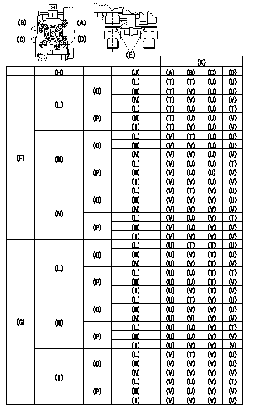
After idle adjustment, measure the idle injection quantities of (A) to (D).
Install the colored rings to the delivery valve holders (A) to (D) in accordance with the table.
(A): A cylinder (B) :B cylinder (C) : C cylinder (D): D cylinder
(E): Collar ring
(F): (A) >= (C)
(G): (C) > (A)
(H): (A) - (C) or (C) - (A)
(I): 0.2, 0.1(mm3/st)
(J): (B) - (D) or (D) - (B)
(K): Ring color
(L): At least 0.6 mm3/st
(M): 0.3, 0.4, 0.5 (mm3/st)
(N): 0.2, 0.1, 0.0 (mm3/st)
(O): (B) >= (D)
(P): (D) > (B)
(T): Yellow
(U): White
(V): Red
----------
----------
----------
----------
0000001901 WIRE

Confirmation of the wire length:
Accelerator wire: Idle-full stroke: L1
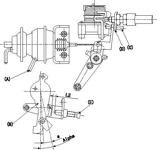
Adjustment of the double stage actuator:
(1)Apply negative pressure P1 {P2} to the actuator through the negative pressure inlet port (A).
(2)In status (1) above, adjust screw (C) so that the control lever (B) position is a [ie, the gap between the control lever and the idle switch (E) is (L2)]. Fix by tightening the nut (D).
TT
----------
L1=34.1+-3.5mm L2=2.7+-0.5mm a=7deg P1=-66.6kPa P2=-500mmHg T=6~9N-m(0.6~0.9kgf-m)
----------
L2=2.7+-0.5mm a=7deg Alpha=12.5deg
----------
L1=34.1+-3.5mm L2=2.7+-0.5mm a=7deg P1=-66.6kPa P2=-500mmHg T=6~9N-m(0.6~0.9kgf-m)
----------
L2=2.7+-0.5mm a=7deg Alpha=12.5deg
Information:
43. Install inner fuel injection lines (27). Use tool (H) and (J) and tighten the fuel injection line nuts to a torque of 30 5 lb. ft. (40 7 N m). 44. Make sure seals (28) are in position on the valve cover bases. Put valve cover bases (29) in position on the cylinder head. 45. Install bolts (32) that hold the valve cover bases in place. Tighten the bolts to a torque of 120 24 lb.in. (13.6 2.8 N m).46. Make sure seals (30) are in position on the valve covers. Put valve covers (31) in position on the valve cover bases. Install bolts (33) that hold the valve covers in place. Tighten the bolts to a torque of 120 24 lb.in. (13.6 2.8 N m).47. If the fan drive group was not removed, install bolts (34) that hold the bracket on the head to the timing gear cover. 48. Put breather (35) and breather tube (36) in position on the valve cover. Install the three clamps that hold them in place.49. Connect hose (37) to the cylinder head. 50. Connect air compressor water line (38) to the air compressor. 51. Connect outer fuel injection lines (39). Tighten the nuts to a torque of 30 5 lb.ft. (40 7 N m). 52. Install water temperature sensing units (42) and (43). Connect wires (40) and (41) to the water temperature sensing units. Install turbocharger tube (47), elbow (45) and inlet manifold (44) as a unit.53. Put the inlet manifold gaskets in place on the cylinder head. Put SAE 30W oil on O-ring seals (46). Slide turbocharger tube (47) into the turbocharger. Put 9S3263 Thread Lock on the threads of the bolts and install the twelve bolts that hold the inlet manifold to the cylinder head. 54. Connect oil line (48) for the fuel ratio control to the inlet manifold.55. Connect fuel lines (49), (50) and (51) to the fuel block. 56. Connect fuel line (52) to the fuel filter base. 57. Make sure the gasket is in place and put priming pump (55) in position. Install bolts (54).58. Install brackets (53) on the inlet manifold. 59. Put the gasket in place and install two bolts (57) that hold the oil drain tube to the turbocharger.60. Put the gasket in position for the oil supply tube. Install oil supply tube (56).61. If the fan drive group was removed, install the fan drive. See DISASSEMBLY AND ASSEMBLY section. 62. Put air conditioning compressor (58) in position on bracket (59). Install the four bolts that hold the compressor to the bracket. 63. Put gasket (60) in position. Install water temperature regulator (61) in the water temperature regulator housing. Install the water temperature regulator housing (62) on the cylinder head. 64. Connect the water vent line to the head. Put upper radiator hose (63) in position on the water temperature regulator housing and the radiator. Tighten the clamps that hold the upper radiator hose
Have questions with 104740-0940?
Group cross 104740-0940 ZEXEL
104740-0940
INJECTION-PUMP ASSEMBLY