Information injection-pump assembly
BOSCH
9 460 610 979
9460610979
ZEXEL
104740-0731
1047400731
Rating:
Components :
| 0. | INJECTION-PUMP ASSEMBLY | 104740-0731 |
| 1. | _ | |
| 2. | FUEL INJECTION PUMP | 104640-0731 |
| 3. | NUMBER PLATE | 146990-2500 |
| 4. | _ | |
| 5. | CAPSULE | 146620-0120 |
| 6. | ADJUSTING DEVICE | 146679-4120 |
| 7. | NOZZLE AND HOLDER ASSY | 105148-1183 |
| 8. | Nozzle and Holder | PN40 13 H50C |
| 9. | Open Pre:MPa(Kqf/cm2) | 10.8{110} |
| 10. | NOZZLE-HOLDER | 105078-0111 |
| 11. | NOZZLE | 105007-1210 |
Scheme ###:
| 1/6. | [1] | 146601-0700 | PACKING RING |
| 6. | [1] | 146100-0720 | SUPPLY PUMP |
| 9. | [1] | 146103-0100 | COVER |
| 10. | [2] | 139104-0000 | FLAT-HEAD SCREW |
| 12. | [1] | 146200-0420 | DRIVE SHAFT |
| 12/1. | [1] | 146200-0400 | DRIVE SHAFT |
| 12/2. | [1] | 146201-0000 | WOODRUFF KEY |
| 12/3. | [2] | 146202-0100 | DAMPER |
| 12/4. | [1] | 146203-0000 | TOOTHED GEAR |
| 17. | [1] | 146204-0000 | PLAIN WASHER |
| 20. | [1] | 146210-5320 | ROLLER SET |
| 24. | [1] | 146303-0100 | BEARING PIN |
| 25. | [1] | 146304-0000 | BEARING PIN |
| 26. | [1] | 146305-0000 | CLAMPING BAND |
| 27. | [1] | 146205-0000 | SLOTTED WASHER |
| 29. | [1] | 146220-4720 | CAM PLATE |
| 30. | [1] | 146600-0800 | O-RING |
| 31. | [1] | 146311-7020 | PUMP PLUNGER |
| 32. | [1] | 146301-0000 | SLIDING PIECE |
| 34. | [1] | 146312-2800 | COMPRESSION SPRING |
| 34B. | [1] | 146312-2700 | COMPRESSION SPRING |
| 34C. | [1] | 146312-2900 | COMPRESSION SPRING |
| 35/1. | [1] | 146690-3200 | SHIM D11.5&9.4T0.1 |
| 35/1. | [1] | 146690-3300 | SHIM D11.5&9.4T0.2 |
| 35/1. | [1] | 146690-3400 | SHIM D11.5&9.4T0.25 |
| 35/1. | [1] | 146690-3500 | SHIM D11.5&9.4T1.0 |
| 35/1. | [1] | 146690-4100 | SHIM D11.5&9.4T2 |
| 35/1. | [1] | 146690-4200 | SHIM D11.5&9.4T0.5 |
| 35/1. | [1] | 146690-4300 | SHIM D11.5&9.4T0.75 |
| 36. | [1] | 146600-0800 | O-RING |
| 37. | [1] | 146310-1600 | COVER |
| 38. | [2] | 146620-5000 | BLEEDER SCREW |
| 39. | [1] | 146310-0100 | COVER |
| 40. | [2] | 146620-5000 | BLEEDER SCREW |
| 41. | [1] | 146312-3300 | COMPRESSION SPRING |
| 42. | [1] | 146602-8500 | PLAIN WASHER |
| 43. | [1] | 146230-0000 | SHIM |
| 44. | [1] | 146230-0100 | PLAIN WASHER |
| 45. | [1] | 146231-0001 | SLOTTED WASHER |
| 47. | [2] | 146233-0000 | SLOTTED WASHER |
| 48/1. | [1] | 146603-0000 | SHIM D17.0&5.2T0.50 |
| 48/1. | [1] | 146603-0100 | SHIM D17.0&5.2T0.80 |
| 48/1. | [1] | 146603-0200 | SHIM D17.0&5.2T1.00 |
| 48/1. | [1] | 146603-0300 | SHIM D17.0&5.2T1.20 |
| 48/1. | [1] | 146603-0400 | SHIM D17.0&5.2T1.50 |
| 48/1. | [1] | 146603-0500 | SHIM D17.0&5.2T1.80 |
| 48/1. | [1] | 146603-0600 | SHIM D17.0&5.2T2.00 |
| 48/1. | [1] | 146690-1400 | SHIM D17&5.2T0.9 |
| 48/1. | [1] | 146690-1500 | SHIM D17&5.2T1.1 |
| 48/1. | [1] | 146690-1600 | SHIM D17&5.2T1.3 |
| 48/1. | [1] | 146690-1700 | SHIM D17&5.2T1.4 |
| 48/1. | [1] | 146690-1800 | SHIM D17&5.2T1.6 |
| 48/1. | [1] | 146690-1900 | SHIM D17&5.2T1.7 |
| 48/1. | [1] | 146690-5800 | SHIM |
| 48/1. | [1] | 146690-5900 | SHIM |
| 48/1. | [1] | 146690-6000 | SHIM |
| 48/1. | [1] | 146690-6100 | SHIM |
| 48/1. | [1] | 146690-6200 | SHIM |
| 48/1. | [1] | 146690-6300 | SHIM |
| 48/1. | [1] | 146690-6400 | SHIM |
| 48/1. | [1] | 146690-6500 | SHIM |
| 48/1. | [1] | 146690-6600 | SHIM |
| 48/1. | [1] | 146690-6700 | SHIM |
| 48/1. | [1] | 146690-6800 | SHIM |
| 48/1. | [1] | 146690-6900 | SHIM |
| 48/1. | [1] | 146690-7000 | SHIM |
| 48/1. | [1] | 146690-7100 | SHIM |
| 48/1. | [1] | 146690-7200 | SHIM |
| 48/1. | [1] | 146690-7300 | SHIM |
| 48/1. | [1] | 146690-7400 | SHIM |
| 48/1. | [1] | 146690-7500 | SHIM |
| 48/1. | [1] | 146690-7800 | SHIM |
| 49. | [2] | 146234-0120 | GUIDE PIN |
| 50. | [1] | 146403-6820 | HYDRAULIC HEAD |
| 50. | [1] | 146403-6820 | HYDRAULIC HEAD |
| 50. | [1] | 146403-6820 | HYDRAULIC HEAD |
| 51. | [1] | 146600-0000 | O-RING |
| 52/1. | [1] | 146420-0000 | SHIM D9.5&3.0T1.90 |
| 52/1. | [1] | 146420-0100 | SHIM D9.5&3.0T1.92 |
| 52/1. | [1] | 146420-0200 | SHIM D9.5&3.0T1.94 |
| 52/1. | [1] | 146420-0300 | SHIM D9.5&3.0T1.96 |
| 52/1. | [1] | 146420-0400 | SHIM D9.5&3.0T1.98 |
| 52/1. | [1] | 146420-0500 | SHIM D9.5&3.0T2.00 |
| 52/1. | [1] | 146420-0600 | SHIM D9.5&3.0T2.02 |
| 52/1. | [1] | 146420-0700 | SHIM D9.5&3.0T2.04 |
| 52/1. | [1] | 146420-0800 | SHIM D9.5&3.0T2.06 |
| 52/1. | [1] | 146420-0900 | SHIM D9.5&3.0T2.08 |
| 52/1. | [1] | 146420-1000 | SHIM D9.5&3.0T2.10 |
| 52/1. | [1] | 146420-1100 | SHIM D9.5&3.0T2.12 |
| 52/1. | [1] | 146420-1200 | SHIM D9.5&3.0T2.14 |
| 52/1. | [1] | 146420-1300 | SHIM D9.5&3.0T2.16 |
| 52/1. | [1] | 146420-1400 | SHIM D9.5&3.0T2.18 |
| 52/1. | [1] | 146420-1500 | SHIM D9.5&3.0T2.20 |
| 52/1. | [1] | 146420-1600 | SHIM D9.5&3.0T2.22 |
| 52/1. | [1] | 146420-1700 | SHIM D9.5&3.0T2.24 |
| 52/1. | [1] | 146420-1800 | SHIM D9.5&3.0T2.26 |
| 52/1. | [1] | 146420-1900 | SHIM D9.5&3.0T2.28 |
| 52/1. | [1] | 146420-2000 | SHIM D9.5&3.0T2.30 |
| 52/1. | [1] | 146420-2100 | SHIM D9.5&3.0T2.32 |
| 52/1. | [1] | 146420-2200 | SHIM D9.5&3.0T2.34 |
| 52/1. | [1] | 146420-2300 | SHIM D9.5&3.0T2.36 |
| 52/1. | [1] | 146420-2400 | SHIM D9.5&3.0T2.38 |
| 52/1. | [1] | 146420-2500 | SHIM D9.5&3.0T2.40 |
| 52/1. | [1] | 146420-2600 | SHIM D9.5&3.0T2.42 |
| 52/1. | [1] | 146420-2700 | SHIM D9.5&3.0T2.44 |
| 52/1. | [1] | 146420-2800 | SHIM D9.5&3.0T2.46 |
| 52/1. | [1] | 146420-2900 | SHIM D9.5&3.0T2.48 |
| 52/1. | [1] | 146420-3000 | SHIM D9.5&3.0T2.50 |
| 52/1. | [1] | 146420-3100 | SHIM D9.5&3.0T2.52 |
| 52/1. | [1] | 146420-3200 | SHIM D9.5&3.0T2.54 |
| 52/1. | [1] | 146420-3300 | SHIM D9.5&3.0T2.56 |
| 52/1. | [1] | 146420-3400 | SHIM D9.5&3.0T2.58 |
| 52/1. | [1] | 146420-3500 | SHIM D9.5&3.0T2.60 |
| 52/1. | [1] | 146420-3600 | SHIM D9.5&3.0T2.62 |
| 52/1. | [1] | 146420-3700 | SHIM D9.5&3.0T2.64 |
| 52/1. | [1] | 146420-3800 | SHIM D9.5&3.0T2.66 |
| 52/1. | [1] | 146420-3900 | SHIM D9.5&3.0T2.68 |
| 52/1. | [1] | 146420-4000 | SHIM D9.5&3.0T2.70 |
| 52/1. | [1] | 146420-4100 | SHIM D9.5&3.0T2.72 |
| 52/1. | [1] | 146420-4200 | SHIM D9.5&3.0T2.74 |
| 52/1. | [1] | 146420-4300 | SHIM D9.5&3.0T2.76 |
| 52/1. | [1] | 146420-4400 | SHIM D9.5&3.0T2.78 |
| 52/1. | [1] | 146420-4500 | SHIM D9.5&3.0T2.80 |
| 52/1. | [1] | 146420-4600 | SHIM D9.5&3.0T2.82 |
| 52/1. | [1] | 146420-4700 | SHIM D9.5&3.0T2.84 |
| 52/1. | [1] | 146420-4800 | SHIM D9.5&3.0T2.86 |
| 52/1. | [1] | 146420-4900 | SHIM D9.5&3.0T2.88 |
| 52/1. | [1] | 146420-5000 | SHIM D9.5&3.0T2.90 |
| 52/1. | [1] | 146420-5100 | SHIM D9.5&3.0T1.74 |
| 52/1. | [1] | 146420-5200 | SHIM D9.5&3.0T1.76 |
| 52/1. | [1] | 146420-5300 | SHIM D9.5&3.0T1.78 |
| 52/1. | [1] | 146420-5400 | SHIM D9.5&3.0T1.80 |
| 52/1. | [1] | 146420-5500 | SHIM D9.5&3.0T1.82 |
| 52/1. | [1] | 146420-5600 | SHIM D9.5&3.0T1.84 |
| 52/1. | [1] | 146420-5700 | SHIM D9.5&3.0T1.86 |
| 52/1. | [1] | 146420-5800 | SHIM D9.5&3.0T1.88 |
| 54. | [4] | 146433-0100 | GASKET D12&6.4T1.00 |
| 55. | [4] | 146430-5720 | DELIVERY-VALVE ASSEMBLY |
| 56. | [4] | 146432-0000 | COMPRESSION SPRING |
| 58. | [4] | 146440-0220 | FITTING |
| 60. | [3] | 139106-0100 | FLAT-HEAD SCREW |
| 66. | [1] | 146600-0100 | O-RING |
| 67. | [1] | 146703-7320 | COMPENSATOR,MANIFOLD-PRES |
| 67/1. | [1] | 146806-1820 | GOVERNOR COVER |
| 67/14. | [1] | 146621-1800 | UNION NUT |
| 67/16. | [1] | 146526-3500 | BLEEDER SCREW |
| 67/23. | [1] | 146933-0200 | BRACKET |
| 67/24. | [2] | 010206-2240 | HEX-SOCKET-HEAD CAP SCREW |
| 67/26. | [1] | 146507-0300 | ADAPTOR |
| 67/31. | [1] | 146710-0700 | BUSHING |
| 67/32. | [1] | 146711-0000 | PLATE |
| 67/33. | [1] | 139218-0400 | UNION NUT |
| 67/34. | [1] | 146712-1700 | BEARING PIN |
| 67/35. | [1] | 146621-0300 | UNION NUT |
| 67/36. | [1] | 146600-1400 | O-RING |
| 67/37. | [1] | 146710-0100 | BUSHING |
| 67/38. | [1] | 139506-0200 | GASKET D8.9&6.8T1.00 |
| 67/39. | [1] | 146620-0300 | CAPSULE |
| 67/40. | [1] | 026512-1540 | GASKET D15.4&12.2T1.50 |
| 67/41. | [1] | 146713-4500 | ADJUSTING PIN |
| 67/42. | [2] | 146714-0200 | PLATE |
| 67/43. | [1] | 146715-0300 | DIAPHRAGM |
| 67/44. | [1] | 139306-0100 | LOCKING WASHER |
| 67/45. | [1] | 013030-6040 | UNION NUT M6P1H3.6 |
| 67/46. | [1] | 146716-0000 | UNION NUT |
| 67/47. | [1] | 146717-2900 | COILED SPRING |
| 67/48/1. | [1] | 146720-3000 | SPACER BUSHING L3.7 |
| 67/48/1. | [1] | 146720-3100 | SPACER BUSHING L3.9 |
| 67/48/1. | [1] | 146720-3200 | SPACER BUSHING L4.1 |
| 67/48/1. | [1] | 146720-3300 | SPACER BUSHING L4.3 |
| 67/48/1. | [1] | 146720-3400 | SPACER BUSHING L4.5 |
| 67/48/1. | [1] | 146720-3500 | SPACER BUSHING L4.7 |
| 67/48/1. | [1] | 146720-3600 | SPACER BUSHING L4.9 |
| 67/48/1. | [1] | 146720-3700 | SPACER BUSHING L5.1 |
| 67/48/1. | [1] | 146720-3800 | SPACER BUSHING L5.3 |
| 67/48/1. | [1] | 146720-3900 | SPACER BUSHING L5.5 |
| 67/48/1. | [1] | 146720-4000 | SPACER BUSHING L5.7 |
| 67/48/1. | [1] | 146720-4100 | SPACER BUSHING L5.9 |
| 67/48/1. | [1] | 146720-4200 | SPACER BUSHING L6.1 |
| 67/48/1. | [1] | 146720-4300 | SPACER BUSHING L6.3 |
| 67/48/1. | [1] | 146720-4400 | SPACER BUSHING L6.5 |
| 67/48/1. | [1] | 146720-8900 | SPACER BUSHING L6.7 |
| 67/48/1. | [1] | 146720-9000 | SPACER BUSHING L6.9 |
| 67/48/1. | [1] | 146720-9100 | SPACER BUSHING L7.1 |
| 67/48/1. | [1] | 146720-9200 | SPACER BUSHING L7.3 |
| 67/48/1. | [1] | 146720-9300 | SPACER BUSHING L7.5 |
| 67/48/1. | [1] | 146720-9400 | SPACER BUSHING L7.7 |
| 67/48/1. | [1] | 146720-9500 | SPACER BUSHING L7.9 |
| 67/48/1. | [1] | 146720-9600 | SPACER BUSHING L8.1 |
| 67/48/1. | [1] | 146720-9700 | SPACER BUSHING L8.3 |
| 67/48/1. | [1] | 146720-9800 | SPACER BUSHING L8.5 |
| 67/48/1. | [1] | 146720-9900 | SPACER BUSHING L3.6 |
| 67/48/1. | [1] | 146725-0000 | SPACER BUSHING L3.8 |
| 67/48/1. | [1] | 146725-0100 | SPACER BUSHING L4.0 |
| 67/48/1. | [1] | 146725-0200 | SPACER BUSHING L4.2 |
| 67/48/1. | [1] | 146725-0300 | SPACER BUSHING L4.4 |
| 67/48/1. | [1] | 146725-0400 | SPACER BUSHING L4.6 |
| 67/48/1. | [1] | 146725-0500 | SPACER BUSHING L4.8 |
| 67/48/1. | [1] | 146725-0600 | SPACER BUSHING L5.0 |
| 67/48/1. | [1] | 146725-0700 | SPACER BUSHING L5.2 |
| 67/48/1. | [1] | 146725-0800 | SPACER BUSHING L5.4 |
| 67/48/1. | [1] | 146725-0900 | SPACER BUSHING L5.6 |
| 67/48/1. | [1] | 146725-1000 | SPACER BUSHING L5.8 |
| 67/48/1. | [1] | 146725-1100 | SPACER BUSHING L6.0 |
| 67/48/1. | [1] | 146725-1200 | SPACER BUSHING L6.2 |
| 67/48/1. | [1] | 146725-1300 | SPACER BUSHING L6.4 |
| 67/48/1. | [1] | 146725-1400 | SPACER BUSHING L6.6 |
| 67/48/1. | [1] | 146725-1500 | SPACER BUSHING L6.8 |
| 67/48/1. | [1] | 146725-1600 | SPACER BUSHING L7.0 |
| 67/48/1. | [1] | 146725-1700 | SPACER BUSHING L7.2 |
| 67/48/1. | [1] | 146725-1800 | SPACER BUSHING L7.4 |
| 67/48/1. | [1] | 146725-1900 | SPACER BUSHING L7.6 |
| 67/48/1. | [1] | 146725-2000 | SPACER BUSHING L7.8 |
| 67/48/1. | [1] | 146725-2100 | SPACER BUSHING L8.0 |
| 67/48/1. | [1] | 146725-2200 | SPACER BUSHING L8.2 |
| 67/48/1. | [1] | 146725-2300 | SPACER BUSHING L8.4 |
| 67/48/1. | [1] | 146725-2400 | SPACER BUSHING L8.6 |
| 67/49. | [1] | 146721-4120 | COVER |
| 67/50. | [1] | 146722-0200 | FLAT-HEAD SCREW |
| 67/51. | [1] | 146600-0300 | O-RING |
| 67/52. | [1] | 013020-6040 | UNION NUT M6P1H5 |
| 67/53. | [1] | 146620-9400 | BLEEDER SCREW |
| 67/54. | [1] | 146620-4600 | BLEEDER SCREW |
| 67/55. | [2] | 139006-4500 | BLEEDER SCREW |
| 67/56. | [1] | 146723-0200 | CONTROL LEVER |
| 67/57. | [1] | 146712-0100 | BEARING PIN |
| 67/58. | [2] | 146620-0600 | CAPSULE |
| 67/59. | [2] | 026506-1040 | GASKET D9.9&6.2T1 |
| 67/60. | [1] | 146724-0300 | ELEMENT |
| 67/61. | [1] | 146724-0600 | CAPSULE |
| 67/64. | [1] | 146933-6300 | BRACKET |
| 67/78. | [1] | 146600-4400 | SEAL RING |
| 67/98. | [1] | 146648-2800 | SPACER BUSHING |
| 67/100. | [1] | 146932-7500 | BRACKET |
| 67/108. | [1] | 146932-4001 | BRACKET |
| 67/109. | [1] | 010206-1240 | HEX-SOCKET-HEAD CAP SCREW M6P1L12 |
| 67/110. | [1] | 014020-6140 | PLAIN WASHER |
| 67/111. | [1] | 139006-4400 | BLEEDER SCREW |
| 67/112. | [1] | 014010-6140 | PLAIN WASHER D13&6.5T1 |
| 67/200. | [1] | 139308-0300 | PLAIN WASHER |
| 67/201. | [1] | 146545-4100 | THREADED PIN |
| 67/201B. | [1] | 146545-4200 | THREADED PIN |
| 67/201C. | [1] | 146545-4300 | THREADED PIN |
| 67/202. | [1] | 139208-0900 | UNION NUT |
| 67/203. | [1] | 146600-1200 | O-RING |
| 68. | [1] | 146810-2820 | CONTROL SHAFT |
| 69. | [1] | 139310-0200 | PLAIN WASHER |
| 72. | [1] | 146831-6520 | CONTROL LEVER |
| 72B. | [1] | 146831-6620 | CONTROL LEVER |
| 73. | [1] | 014110-6440 | LOCKING WASHER |
| 75. | [1] | 146621-0700 | UNION NUT |
| 95. | [1] | 146861-7720 | FULCRUM LEVER |
| 104. | [2] | 146568-0000 | SLOTTED SPRING PIN |
| 105. | [2] | 026508-1140 | GASKET D11.4&8.2T1 |
| 106. | [2] | 146588-0500 | COILED SPRING |
| 107. | [1] | 146569-0300 | UNION NUT |
| 108. | [1] | 146570-0420 | GOVERNOR SHAFT |
| 109. | [1] | 146600-0400 | O-RING |
| 110/1. | [1] | 146571-0000 | SHIM D20.2&8.3T1.05 |
| 110/1. | [1] | 146571-0100 | SHIM D20.2&8.3T1.25 |
| 110/1. | [1] | 146571-0200 | SHIM D20.2&8.3T1.45 |
| 110/1. | [1] | 146571-0300 | SHIM D20.2&8.3T1.65 |
| 110/1. | [1] | 146571-0400 | SHIM D20.2&8.3T1.85 |
| 110/1. | [1] | 146571-0500 | SHIM D20.2&8.3T1.15 |
| 110/1. | [1] | 146571-0600 | SHIM D20.2&8.3T1.35 |
| 110/1. | [1] | 146571-0700 | SHIM D20.2&8.3T1.55 |
| 110/1. | [1] | 146571-0800 | SHIM D20.2&8.3T1.75 |
| 111. | [1] | 146602-0600 | PLAIN WASHER D20&8.4T1.40 |
| 112. | [1] | 146572-0020 | FLYWEIGHT ASSEMBLY |
| 114. | [1] | 146602-0500 | PLAIN WASHER D17&6.4T1.60 |
| 115. | [1] | 146975-5000 | SLIDING SLEEVE |
| 116. | [1] | 146576-0200 | CAP |
| 117/1. | [1] | 146577-1800 | PLUG L2.10 |
| 117/1. | [1] | 146577-1900 | PLUG L2.30 |
| 117/1. | [1] | 146577-2000 | PLUG L2.50 |
| 117/1. | [1] | 146577-2100 | PLUG L2.70 |
| 117/1. | [1] | 146577-2200 | PLUG L2.90 |
| 117/1. | [1] | 146577-2300 | PLUG L3.10 |
| 117/1. | [1] | 146577-2400 | PLUG L3.30 |
| 117/1. | [1] | 146577-2500 | PLUG L3.50 |
| 117/1. | [1] | 146577-2600 | PLUG L3.70 |
| 117/1. | [1] | 146577-2700 | PLUG L3.90 |
| 117/1. | [1] | 146577-2800 | PLUG L4.10 |
| 117/1. | [1] | 146577-2900 | PLUG L4.30 |
| 117/1. | [1] | 146577-3000 | PLUG L4.50 |
| 117/1. | [1] | 146577-3100 | PLUG L4.70 |
| 117/1. | [1] | 146577-3200 | PLUG L4.90 |
| 117/1. | [1] | 146577-3300 | PLUG L5.10 |
| 117/1. | [1] | 146577-6700 | PLUG L2.2 |
| 117/1. | [1] | 146577-6800 | PLUG L2.4 |
| 117/1. | [1] | 146577-6900 | PLUG L2.6 |
| 117/1. | [1] | 146577-7000 | PLUG L2.8 |
| 117/1. | [1] | 146577-7100 | PLUG L3.0 |
| 117/1. | [1] | 146577-7200 | PLUG L3.2 |
| 117/1. | [1] | 146577-7300 | PLUG L3.4 |
| 117/1. | [1] | 146577-7400 | PLUG L3.6 |
| 117/1. | [1] | 146577-7500 | PLUG L3.8 |
| 117/1. | [1] | 146577-7600 | PLUG L4.0 |
| 117/1. | [1] | 146577-7700 | PLUG L4.2 |
| 117/1. | [1] | 146577-7800 | PLUG L4.4 |
| 117/1. | [1] | 146577-7900 | PLUG L4.6 |
| 117/1. | [1] | 146577-8000 | PLUG L4.8 |
| 117/1. | [1] | 146577-8100 | PLUG L5.0 |
| 117/1. | [1] | 146877-0000 | PLUG L5.2 |
| 117/1. | [1] | 146877-0100 | PLUG L5.3 |
| 117/1. | [1] | 146877-0200 | PLUG L5.4 |
| 117/1. | [1] | 146877-0300 | PLUG L5.5 |
| 117/1. | [1] | 146877-4700 | PLUG |
| 117/1. | [1] | 146877-4800 | PLUG |
| 117/1. | [1] | 146877-4900 | PLUG |
| 117/1. | [1] | 146877-5000 | PLUG |
| 123. | [4] | 146620-0500 | HEX-SOCKET-HEAD CAP SCREW |
| 130. | [1] | 146421-0020 | CAPSULE |
| 130/2. | [1] | 026508-1140 | GASKET D11.4&8.2T1 |
| 130/3. | [1] | 146422-0000 | BLEEDER SCREW |
| 130/4. | [1] | 146600-0500 | O-RING |
| 133. | [1] | 146600-0600 | O-RING |
| 134. | [1] | 146600-0700 | O-RING |
| 135. | [1] | 146110-0920 | CONTROL VALVE |
| 135/5. | [1] | 146114-0000 | SPRING WASHER |
| 136. | [1] | 146120-0020 | OVER FLOW VALVE |
| 137. | [2] | 139512-0500 | GASKET |
| 138. | [1] | 146667-0520 | INLET UNION |
| 162. | [1] | 146625-8020 | PLATE |
| 200. | [1] | 146206-0100 | COILED SPRING |
| 205. | [1] | 146201-0100 | WOODRUFF KEY |
| 214. | [1] | 146542-1400 | BUSHING |
| 215. | [1] | 146542-1500 | BUSHING |
| 217. | [1] | 146542-2600 | SLOTTED WASHER |
| 218. | [1] | 146592-8500 | COILED SPRING |
| 219. | [1] | 146541-3000 | BUSHING |
| 220. | [1] | 146592-8300 | COILED SPRING |
| 221. | [1] | 146933-1120 | BRACKET |
| 222. | [1] | 010206-1440 | HEX-SOCKET-HEAD CAP SCREW M6P1L14 |
| 223. | [1] | 146670-9620 | SWITCH |
| 236. | [3] | 139006-4800 | BLEEDER SCREW |
| 236. | [3] | 139006-4800 | BLEEDER SCREW |
| 237. | [1] | 146620-0200 | HEX-SOCKET-HEAD CAP SCREW |
| 240. | [1] | 146650-4320 | PULLING ELECTROMAGNET |
| 240/8. | [1] | 146600-1700 | O-RING |
| 243. | [1] | 146621-1000 | UNION NUT |
| 244. | [1] | 010206-1040 | HEX-SOCKET-HEAD CAP SCREW |
| 245. | [3] | 139512-0500 | GASKET |
| 246. | [1] | 139812-1900 | EYE BOLT |
| 247. | [1] | 146667-0820 | INLET UNION |
| 248. | [1] | 146614-0200 | SPACER BUSHING |
| 251. | [1] | 146125-0101 | FILTER |
| 252. | [1] | 146125-0200 | COILED SPRING |
| 275. | [1] | 146932-8000 | BRACKET |
| 310. | [1] | 146684-6920 | POTENTCIOMETER |
| 310/2. | [2] | 139104-0400 | FLAT-HEAD SCREW |
| 310/3. | [1] | 146620-1500 | FLAT-HEAD SCREW |
| 310/4. | [1] | 013020-6040 | UNION NUT M6P1H5 |
| 310/5. | [1] | 146614-2300 | JOINT CONNECTION |
| 310/6. | [1] | 146661-0401 | BOOT |
| 312. | [1] | 146932-8120 | BRACKET |
| 313. | [2] | 010006-0840 | BLEEDER SCREW M6P1L8 |
| 317. | [2] | 010206-1040 | HEX-SOCKET-HEAD CAP SCREW |
| 318. | [1] | 146932-8320 | BRACKET |
| 800S. | [1] | 146018-6920 | PUMP HOUSING |
| 800S/1/6. | [1] | 146601-0700 | PACKING RING |
| 804S. | [1] | 146232-0720 | COMPRESSION SPRING |
| 805S. | [1] | 146574-0120 | PARTS SET |
| 810S. | [1] | 146600-2420 | REPAIR SET |
| 812S. | [1] | 146600-1920 | PARTS SET |
| 821S. | [1] | 146210-5820 | ROLLER SET |
| 835S. | [1] | 146598-1000 | CAP |
| 836S/1. | [1] | 146598-0600 | CAP L18 |
| 836S/1. | [1] | 146598-0700 | CAP L21 |
| 836S/1. | [1] | 146598-0800 | CAP L24 |
| 836S/1. | [1] | 146598-0900 | CAP L27 |
| 847S. | [1] | 146684-7010 | POTENTCIOMETER |
| 903. | [1] | 146620-0120 | CAPSULE |
| 903/2. | [1] | 146600-1300 | O-RING &13W1.9 |
| 905. | [1] | 146679-4120 | ACTUATOR |
| 906. | [1] | 146990-2500 | NAMEPLATE |
| 912. | [2] | 010206-1440 | HEX-SOCKET-HEAD CAP SCREW M6P1L14 |
| 924. | [1] | 146680-5620 | DAMPER |
| 925. | [2] | 020146-1270 | BLEEDER SCREW |
Include in #2:
104740-0731
as INJECTION-PUMP ASSEMBLY
Cross reference number
BOSCH
9 460 610 979
9460610979
ZEXEL
104740-0731
1047400731
Zexel num
Bosch num
Firm num
Name
Calibration Data:
Adjustment conditions
Test oil
1404 Test oil ISO4113orSAEJ967d
1404 Test oil ISO4113orSAEJ967d
Test oil temperature
degC
45
45
50
Nozzle
105780-0060
Bosch type code
NP-DN0SD1510
Nozzle holder
105780-2150
Opening pressure
MPa
13
13
13.3
Opening pressure
kgf/cm2
133
133
136
Injection pipe
157805-7320
Injection pipe
Inside diameter - outside diameter - length (mm) mm 2-6-450
Inside diameter - outside diameter - length (mm) mm 2-6-450
Joint assembly
157641-4720
Tube assembly
157641-4020
Transfer pump pressure
kPa
20
20
20
Transfer pump pressure
kgf/cm2
0.2
0.2
0.2
Direction of rotation (viewed from drive side)
Left L
Left L
Injection timing adjustment
Pump speed
r/min
750
750
750
Boost pressure
kPa
0
0
0
Boost pressure
mmHg
0
0
0
Average injection quantity
mm3/st.
47.9
47.4
48.4
Difference in delivery
mm3/st.
4
Basic
*
Oil temperature
degC
50
48
52
Remarks
NA
NA
Injection timing adjustment_02
Pump speed
r/min
750
750
750
Boost pressure
kPa
43.3
42
44.6
Boost pressure
mmHg
325
315
335
Average injection quantity
mm3/st.
64.1
63.6
64.6
Difference in delivery
mm3/st.
5.5
Basic
*
Oil temperature
degC
50
48
52
Remarks
CBS
CBS
Injection timing adjustment_03
Pump speed
r/min
1000
1000
1000
Boost pressure
kPa
80
78.7
81.3
Boost pressure
mmHg
600
590
610
Average injection quantity
mm3/st.
76.3
75.8
76.8
Difference in delivery
mm3/st.
6.5
Basic
*
Oil temperature
degC
50
48
52
Remarks
Full
Full
Injection timing adjustment_04
Pump speed
r/min
750
750
750
Boost pressure
kPa
0
0
0
Boost pressure
mmHg
0
0
0
Average injection quantity
mm3/st.
47.9
46.9
48.9
Difference in delivery
mm3/st.
4.5
Basic
*
Oil temperature
degC
50
48
52
Remarks
NA
NA
Injection timing adjustment_05
Pump speed
r/min
750
750
750
Boost pressure
kPa
43.3
42
44.6
Boost pressure
mmHg
325
315
335
Average injection quantity
mm3/st.
64.1
63.1
65.1
Difference in delivery
mm3/st.
6
Basic
*
Oil temperature
degC
50
48
52
Remarks
CBS
CBS
Injection timing adjustment_06
Pump speed
r/min
1000
1000
1000
Boost pressure
kPa
80
78.7
81.3
Boost pressure
mmHg
600
590
610
Average injection quantity
mm3/st.
76.3
75.3
77.3
Difference in delivery
mm3/st.
7
Basic
*
Oil temperature
degC
50
48
52
Remarks
Full
Full
Injection timing adjustment_07
Pump speed
r/min
2000
2000
2000
Boost pressure
kPa
80
78.7
81.3
Boost pressure
mmHg
600
590
610
Average injection quantity
mm3/st.
67.8
64.3
71.3
Oil temperature
degC
50
48
52
Injection quantity adjustment
Pump speed
r/min
2450
2450
2450
Boost pressure
kPa
80
78.7
81.3
Boost pressure
mmHg
600
590
610
Average injection quantity
mm3/st.
23.5
20.5
26.5
Difference in delivery
mm3/st.
7
Basic
*
Oil temperature
degC
55
52
58
Injection quantity adjustment_02
Pump speed
r/min
2800
2800
2800
Boost pressure
kPa
80
78.7
81.3
Boost pressure
mmHg
600
590
610
Average injection quantity
mm3/st.
6
Oil temperature
degC
55
52
58
Injection quantity adjustment_03
Pump speed
r/min
2450
2450
2450
Boost pressure
kPa
80
78.7
81.3
Boost pressure
mmHg
600
590
610
Average injection quantity
mm3/st.
23.5
13.5
33.5
Difference in delivery
mm3/st.
7.5
Basic
*
Oil temperature
degC
55
52
58
Governor adjustment
Pump speed
r/min
370
370
370
Boost pressure
kPa
0
0
0
Boost pressure
mmHg
0
0
0
Average injection quantity
mm3/st.
10.5
9.5
11.5
Difference in delivery
mm3/st.
1.7
Basic
*
Oil temperature
degC
48
46
50
Governor adjustment_02
Pump speed
r/min
370
370
370
Boost pressure
kPa
0
0
0
Boost pressure
mmHg
0
0
0
Average injection quantity
mm3/st.
10.5
9
12
Difference in delivery
mm3/st.
2.5
Basic
*
Oil temperature
degC
48
46
50
Boost compensator adjustment
Pump speed
r/min
400
400
400
Boost pressure
kPa
0
0
0
Boost pressure
mmHg
0
0
0
Average injection quantity
mm3/st.
17
15
19
Difference in delivery
mm3/st.
3
Oil temperature
degC
48
46
50
Timer adjustment
Pump speed
r/min
150
150
150
Boost pressure
kPa
0
0
0
Boost pressure
mmHg
0
0
0
Average injection quantity
mm3/st.
70
55
90
Basic
*
Oil temperature
degC
48
46
50
Remarks
Full
Full
Timer adjustment_02
Pump speed
r/min
150
150
150
Boost pressure
kPa
0
0
0
Boost pressure
mmHg
0
0
0
Average injection quantity
mm3/st.
70
50
90
Oil temperature
degC
48
46
50
Remarks
Full
Full
Speed control lever angle
Pump speed
r/min
370
370
370
Boost pressure
kPa
0
0
0
Boost pressure
mmHg
0
0
0
Average injection quantity
mm3/st.
0
0
0
Oil temperature
degC
48
46
50
Remarks
Magnet OFF
Magnet OFF
0000000901
Pump speed
r/min
1000
1000
1000
Boost pressure
kPa
80
78.7
81.3
Boost pressure
mmHg
600
590
610
Overflow quantity
cm3/min
400
270
530
Oil temperature
degC
50
48
52
Stop lever angle
Pump speed
r/min
1000
1000
1000
Boost pressure
kPa
80
78.7
81.3
Boost pressure
mmHg
600
590
610
Pressure
kPa
510
481
539
Pressure
kgf/cm2
5.2
4.9
5.5
Basic
*
Oil temperature
degC
50
48
52
Stop lever angle_02
Pump speed
r/min
500
500
500
Boost pressure
kPa
80
78.7
81.3
Boost pressure
mmHg
600
590
610
Pressure
kPa
373
324
422
Pressure
kgf/cm2
3.8
3.3
4.3
Oil temperature
degC
48
46
50
Stop lever angle_03
Pump speed
r/min
1000
1000
1000
Boost pressure
kPa
80
78.7
81.3
Boost pressure
mmHg
600
590
610
Pressure
kPa
510
471
549
Pressure
kgf/cm2
5.2
4.8
5.6
Basic
*
Oil temperature
degC
50
48
52
Stop lever angle_04
Pump speed
r/min
2000
2000
2000
Boost pressure
kPa
80
78.7
81.3
Boost pressure
mmHg
600
590
610
Pressure
kPa
755
706
804
Pressure
kgf/cm2
7.7
7.2
8.2
Oil temperature
degC
50
48
52
0000001101
Pump speed
r/min
1000
1000
1000
Boost pressure
kPa
80
78.7
81.3
Boost pressure
mmHg
600
590
610
Timer stroke
mm
4.4
4.2
4.6
Basic
*
Oil temperature
degC
50
48
52
_02
Pump speed
r/min
500
500
500
Boost pressure
kPa
80
78.7
81.3
Boost pressure
mmHg
600
590
610
Timer stroke
mm
1.8
1
2.6
Oil temperature
degC
48
46
50
_03
Pump speed
r/min
1000
1000
1000
Boost pressure
kPa
80
78.7
81.3
Boost pressure
mmHg
600
590
610
Timer stroke
mm
4.4
4
4.8
Basic
*
Oil temperature
degC
50
48
52
_04
Pump speed
r/min
2000
2000
2000
Boost pressure
kPa
80
78.7
81.3
Boost pressure
mmHg
600
590
610
Timer stroke
mm
9
8.2
9.8
Oil temperature
degC
50
48
52
0000001201
Max. applied voltage
V
8
8
8
Test voltage
V
13
12
14
0000001401
Pump speed
r/min
750
750
750
Boost pressure
kPa
80
78.7
81.3
Boost pressure
mmHg
600
590
610
Average injection quantity
mm3/st.
49
48.5
49.5
Timer stroke TA
mm
2.5
2.3
2.7
Timer stroke variation dT
mm
0.7
0.7
0.7
Basic
*
Oil temperature
degC
50
48
52
_02
Pump speed
r/min
750
750
750
Boost pressure
kPa
80
78.7
81.3
Boost pressure
mmHg
600
590
610
Average injection quantity
mm3/st.
49
48
50
Timer stroke TA
mm
2.5
2.1
2.9
Basic
*
Oil temperature
degC
50
48
52
_03
Pump speed
r/min
750
750
750
Boost pressure
kPa
80
78.7
81.3
Boost pressure
mmHg
600
590
610
Average injection quantity
mm3/st.
30
28.5
31.5
Timer stroke TA
mm
1.5
0.7
2.3
Oil temperature
degC
50
48
52
Timing setting
K dimension
mm
3.3
3.2
3.4
KF dimension
mm
6.01
5.91
6.11
MS dimension
mm
0.9
0.8
1
BCS stroke
mm
6.8
6.6
7
Pre-stroke
mm
0.03
0.01
0.05
Control lever angle alpha
deg.
12.5
8.5
16.5
Control lever angle beta
deg.
40
34
43
Test data Ex:
0000001601 BOOST COMPENSATOR ADJUSTMENT
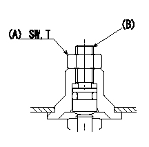
BCS adjustment procedure
1. At full boost pressure, set so that the full injection quantity is within the specifications (adjusting point).
2. Perform boost compensator intermediate operation point adjustment (pump speed N1, boost pressure P1).
3. When injection quantity at boost pressure P2 and pump speed N2 is not as specified, loosen nut (A) and adjust position of screw (B) so that injection quantity is as specified. The screw position should be within +-1 turn of initial position.
4. The nut tightening torque is T.
----------
N1=750r/min N2=750r/min P1=43.3kPa(325mmHg) P2=0kPa(0mmHg) T=6~9N-m(0.6~0.9kgf-m)
----------
SW=10mm T=6~9N-m(0.6~0.9kgf-m)
----------
N1=750r/min N2=750r/min P1=43.3kPa(325mmHg) P2=0kPa(0mmHg) T=6~9N-m(0.6~0.9kgf-m)
----------
SW=10mm T=6~9N-m(0.6~0.9kgf-m)
0000001801 CONTROL STANDARD AT IDLING
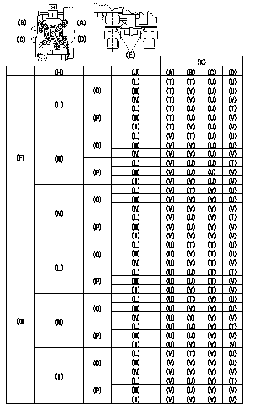
Standards for idle difference in delivery control
After idle adjustment, measure the idle injection quantities of (A) to (D).
Install the colored rings to the delivery valve holders (A) to (D) in accordance with the table.
(A): A cylinder (B) :B cylinder (C) : C cylinder (D): D cylinder
(E): Collar ring
(F): (A) >= (C)
(G): (C) > (A)
(H): (A) - (C) or (C) - (A)
(I): 0.2, 0.1(mm3/st)
(J): (B) - (D) or (D) - (B)
(K): Ring color
(L): At least 0.6 mm3/st
(M): 0.3, 0.4, 0.5 (mm3/st)
(N): 0.2, 0.1, 0.0 (mm3/st)
(O): (B) >= (D)
(P): (D) > (B)
(T): Yellow
(U): White
(V): Red
----------
----------
----------
----------
0000001901 POTENTIOMETER ADJUSTMENT
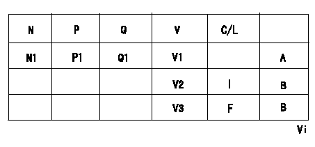
Adjustment of the potentiometer
Dummy bolt method
1. Hold the dummy bolt against the control lever at position N = N1 and Q = Q1 and fix using the lock nut.
2. At potentiometer adjustment, with the control lever contacting the dummy bolt, adjust the potentiometer so that the output voltage is V1.
3. After adjustment, remove the dummy bolt and confirm that the potentiometer output voltage at the control lever's idling and full speed positions is as specified above.
N:Pump speed
P:Boost pressure
Q:Injection quantity
V:Output voltage
A:Adjusting point
B:Checking point
C/L: control lever position
I:Idling
F:Full speed
Vi:Applied voltage
----------
N1=1000r/min Q1=24.6+-1.0mm3/st V1=4.81+-0.03V
----------
N1=1000r/min Q1=24.6+-1.0mm3/st P1=80.0kPa(600mmHg) V1=4.81+-0.03V V2=(2.0+-0.43V) V3=(8.50+-0.48V) Vi=10V
----------
N1=1000r/min Q1=24.6+-1.0mm3/st V1=4.81+-0.03V
----------
N1=1000r/min Q1=24.6+-1.0mm3/st P1=80.0kPa(600mmHg) V1=4.81+-0.03V V2=(2.0+-0.43V) V3=(8.50+-0.48V) Vi=10V
0000002001 WIRE
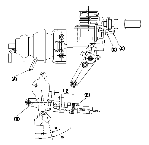
(1)Confirmation of the wire length:
Accelerator wire: Idle-full stroke: L1
(2)Confirmation on the idle SW
Confirm that the switch is ON at the idle lever position.
(3)Adjustment of the double stage actuator:
1. Apply negative pressure P1 to the actuator through the negative pressure suction inlet.
2. Under the conditions in 1. above, adjust using screw (C) so that the control lever () position is angle a [clearance L2+-0.5mm from idle switch (E)], and fix using the nut (D). (Tightening torque T)
b:Angle alpha
----------
L1=34.1+3.5-5.5mm L2=3.8mm P1=-66.6kPa(-500mmHg) a=9deg b=12.5+-4deg T=6~9N-m(0.6~0.9kgf-m)
----------
a=9deg b=12.5+-4deg L2=(3.8mm)
----------
L1=34.1+3.5-5.5mm L2=3.8mm P1=-66.6kPa(-500mmHg) a=9deg b=12.5+-4deg T=6~9N-m(0.6~0.9kgf-m)
----------
a=9deg b=12.5+-4deg L2=(3.8mm)
0000002101 DASHPOT ADJUSTMENT
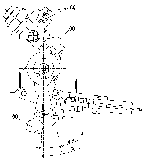
Adjustment of the dash pot
1. Hold the control lever (A) at position a (clearance L).
2. In the above condition, adjust the position of the dash pot so that the end of the dash pot (B) contacts the control lever (A) and fix using the nut (C). (Tightening torque T)
D:Dash pot contact position
b:Angle alpha
----------
L=8.1+-0.05mm T=6~9N-m(0.6~0.9kgf-m) a=14.1deg b=12.5+-4deg
----------
L=8.1+-0.05mm a=14.1deg b=12.5+-4deg
----------
L=8.1+-0.05mm T=6~9N-m(0.6~0.9kgf-m) a=14.1deg b=12.5+-4deg
----------
L=8.1+-0.05mm a=14.1deg b=12.5+-4deg
Information:
b. Operate vehicle at 60% of rated speed with moderate load until oil and coolant temperatures reach their normal range for operation. If there is a heavy vibration, drive shaft whip, tire bounce, etc., do not continue with dynamometer test until cause of the problem is corrected. Engines that have had new internal parts installed should be operated on a run-in schedule before operation at full load. For run-in schedule information, make reference to General Instructions section of this Service Manual.2. Put transmission in direct gear and the differential in the highest speed ratio. Operate vehicle at maximum engine speed and increase chassis dynamometer load until a speed of 50 rpm less than rated speed is reached (continuity light should be on). Maintain this speed for one minute and record the engine speed and wheel horsepower. If horsepower is low and poor maintenance is suspected, remove air cleaner or inlet piping to turbocharger and check horsepower again to see if a plugged air cleaner could be the problem.3a. If the wheel horsepower is correct, find the balance point of the engine (speed at which the load stop pin just touches the torque spring or stop bar). At this point the continuity light should flicker (go off and on dimly). If the balance point is correct, then the low power complaint can not be validated. No further test or repairs are necessary.If the balance point is low, see Procedure No. 5.3b. If the wheel horsepower is below the correct value, find the balance point of the engine (speed at which the load stop pin just touches the torque spring or stop bar). At this point the continuity light should flicker (go off and on dimly). If the balance point is correct, see Procedure No. 6.If the balance point is low, see Procedure No. 4.4. Stop the engine. Remove the AFRC (air-fuel ratio control). Put a cover over the hole where the AFRC was installed. Start the engine and check the balance point and horsepower again. If both of these are now correct, the problem is in AFRC. Repair or replace the AFRC. If, with the AFRC removed, horsepower is now acceptable and balance point is low, the problem is still with AFRC. Repair or replace the AFRC. Then adjust balance point according to Procedure No. 5.5. If the balance point is low, the high idle will have to be increased to raise the balance point to the correct rpm (the point at which the continuity light just comes on). If the balance point is still low and high idle has been adjusted to maximum, disengage clutch while maximum throttle position is maintained. Now observe high idle rpm and, if lower than previously adjusted, check frame-to-engine-mount. A damaged or loose engine mount may put the linkage in a bind and thus prevent maximum governor position at load conditions.6. If the balance point was correct and the wheel horsepower was low, install the 4S6553 Engine Test Group and do the wheel