Information injection-pump assembly
BOSCH
9 460 611 111
9460611111
ZEXEL
104740-0694
1047400694
MAZDA
WL0413800C
wl0413800c
Rating:
Components :
| 0. | INJECTION-PUMP ASSEMBLY | 104740-0694 |
| 1. | _ | |
| 2. | FUEL INJECTION PUMP | 104640-0694 |
| 3. | NUMBER PLATE | 146965-9100 |
| 4. | _ | |
| 5. | CAPSULE | 146620-0120 |
| 6. | ADJUSTING DEVICE | 146679-4120 |
| 7. | NOZZLE AND HOLDER ASSY | 105148-1183 |
| 8. | Nozzle and Holder | PN40 13 H50C |
| 9. | Open Pre:MPa(Kqf/cm2) | 10.8{110} |
| 10. | NOZZLE-HOLDER | 105078-0111 |
| 11. | NOZZLE | 105007-1210 |
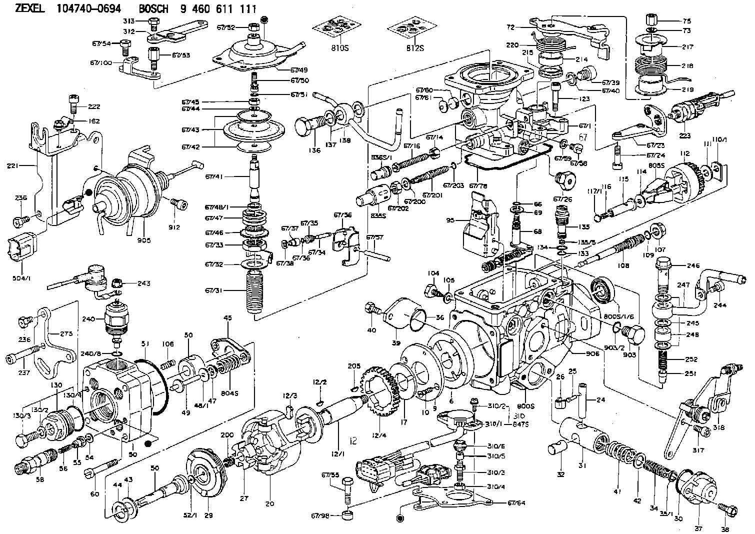
Scheme ###:
| 1/6. | [1] | 146601-0700 | PACKING RING |
| 6. | [1] | 146100-0720 | SUPPLY PUMP |
| 9. | [1] | 146103-0100 | COVER |
| 10. | [2] | 139104-0000 | FLAT-HEAD SCREW |
| 12. | [1] | 146200-0420 | DRIVE SHAFT |
| 12/1. | [1] | 146200-0400 | DRIVE SHAFT |
| 12/2. | [1] | 146201-0000 | WOODRUFF KEY |
| 12/3. | [2] | 146202-0100 | DAMPER |
| 12/4. | [1] | 146203-0000 | TOOTHED GEAR |
| 17. | [1] | 146204-0000 | PLAIN WASHER |
| 20. | [1] | 146210-5320 | ROLLER SET |
| 24. | [1] | 146303-0100 | BEARING PIN |
| 25. | [1] | 146304-0000 | BEARING PIN |
| 26. | [1] | 146305-0000 | CLAMPING BAND |
| 27. | [1] | 146205-0000 | SLOTTED WASHER |
| 29. | [1] | 146220-4720 | CAM PLATE |
| 30. | [1] | 146600-0800 | O-RING |
| 31. | [1] | 146311-7020 | PUMP PLUNGER |
| 32. | [1] | 146301-0400 | SLIDING PIECE |
| 34. | [1] | 146312-2800 | COMPRESSION SPRING |
| 34B. | [1] | 146312-2700 | COMPRESSION SPRING |
| 34C. | [1] | 146312-2900 | COMPRESSION SPRING |
| 35/1. | [1] | 146690-3200 | SHIM D11.5&9.4T0.1 |
| 35/1. | [1] | 146690-3300 | SHIM D11.5&9.4T0.2 |
| 35/1. | [1] | 146690-3400 | SHIM D11.5&9.4T0.25 |
| 35/1. | [1] | 146690-3500 | SHIM D11.5&9.4T1.0 |
| 35/1. | [1] | 146690-4100 | SHIM D11.5&9.4T2 |
| 35/1. | [1] | 146690-4200 | SHIM D11.5&9.4T0.5 |
| 35/1. | [1] | 146690-4300 | SHIM D11.5&9.4T0.75 |
| 36. | [1] | 146600-0800 | O-RING |
| 37. | [1] | 146310-1600 | COVER |
| 38. | [2] | 146620-5000 | BLEEDER SCREW |
| 39. | [1] | 146310-0100 | COVER |
| 40. | [2] | 146620-5000 | BLEEDER SCREW |
| 41. | [1] | 146312-3300 | COMPRESSION SPRING |
| 42. | [1] | 146602-8500 | PLAIN WASHER |
| 43. | [1] | 146230-0000 | SHIM |
| 44. | [1] | 146230-0100 | PLAIN WASHER |
| 45. | [1] | 146231-0001 | SLOTTED WASHER |
| 47. | [2] | 146233-0000 | SLOTTED WASHER |
| 48/1. | [1] | 146603-0000 | SHIM D17.0&5.2T0.50 |
| 48/1. | [1] | 146603-0100 | SHIM D17.0&5.2T0.80 |
| 48/1. | [1] | 146603-0200 | SHIM D17.0&5.2T1.00 |
| 48/1. | [1] | 146603-0300 | SHIM D17.0&5.2T1.20 |
| 48/1. | [1] | 146603-0400 | SHIM D17.0&5.2T1.50 |
| 48/1. | [1] | 146603-0500 | SHIM D17.0&5.2T1.80 |
| 48/1. | [1] | 146603-0600 | SHIM D17.0&5.2T2.00 |
| 48/1. | [1] | 146690-1400 | SHIM D17&5.2T0.9 |
| 48/1. | [1] | 146690-1500 | SHIM D17&5.2T1.1 |
| 48/1. | [1] | 146690-1600 | SHIM D17&5.2T1.3 |
| 48/1. | [1] | 146690-1700 | SHIM D17&5.2T1.4 |
| 48/1. | [1] | 146690-1800 | SHIM D17&5.2T1.6 |
| 48/1. | [1] | 146690-1900 | SHIM D17&5.2T1.7 |
| 48/1. | [1] | 146690-5800 | SHIM |
| 48/1. | [1] | 146690-5900 | SHIM |
| 48/1. | [1] | 146690-6000 | SHIM |
| 48/1. | [1] | 146690-6100 | SHIM |
| 48/1. | [1] | 146690-6200 | SHIM |
| 48/1. | [1] | 146690-6300 | SHIM |
| 48/1. | [1] | 146690-6400 | SHIM |
| 48/1. | [1] | 146690-6500 | SHIM |
| 48/1. | [1] | 146690-6600 | SHIM |
| 48/1. | [1] | 146690-6700 | SHIM |
| 48/1. | [1] | 146690-6800 | SHIM |
| 48/1. | [1] | 146690-6900 | SHIM |
| 48/1. | [1] | 146690-7000 | SHIM |
| 48/1. | [1] | 146690-7100 | SHIM |
| 48/1. | [1] | 146690-7200 | SHIM |
| 48/1. | [1] | 146690-7300 | SHIM |
| 48/1. | [1] | 146690-7400 | SHIM |
| 48/1. | [1] | 146690-7500 | SHIM |
| 48/1. | [1] | 146690-7800 | SHIM |
| 49. | [2] | 146234-0120 | GUIDE PIN |
| 50. | [1] | 146403-6820 | HYDRAULIC HEAD |
| 50. | [1] | 146403-6820 | HYDRAULIC HEAD |
| 50. | [1] | 146403-6820 | HYDRAULIC HEAD |
| 51. | [1] | 146600-0000 | O-RING |
| 52/1. | [1] | 146420-0000 | SHIM D9.5&3.0T1.90 |
| 52/1. | [1] | 146420-0100 | SHIM D9.5&3.0T1.92 |
| 52/1. | [1] | 146420-0200 | SHIM D9.5&3.0T1.94 |
| 52/1. | [1] | 146420-0300 | SHIM D9.5&3.0T1.96 |
| 52/1. | [1] | 146420-0400 | SHIM D9.5&3.0T1.98 |
| 52/1. | [1] | 146420-0500 | SHIM D9.5&3.0T2.00 |
| 52/1. | [1] | 146420-0600 | SHIM D9.5&3.0T2.02 |
| 52/1. | [1] | 146420-0700 | SHIM D9.5&3.0T2.04 |
| 52/1. | [1] | 146420-0800 | SHIM D9.5&3.0T2.06 |
| 52/1. | [1] | 146420-0900 | SHIM D9.5&3.0T2.08 |
| 52/1. | [1] | 146420-1000 | SHIM D9.5&3.0T2.10 |
| 52/1. | [1] | 146420-1100 | SHIM D9.5&3.0T2.12 |
| 52/1. | [1] | 146420-1200 | SHIM D9.5&3.0T2.14 |
| 52/1. | [1] | 146420-1300 | SHIM D9.5&3.0T2.16 |
| 52/1. | [1] | 146420-1400 | SHIM D9.5&3.0T2.18 |
| 52/1. | [1] | 146420-1500 | SHIM D9.5&3.0T2.20 |
| 52/1. | [1] | 146420-1600 | SHIM D9.5&3.0T2.22 |
| 52/1. | [1] | 146420-1700 | SHIM D9.5&3.0T2.24 |
| 52/1. | [1] | 146420-1800 | SHIM D9.5&3.0T2.26 |
| 52/1. | [1] | 146420-1900 | SHIM D9.5&3.0T2.28 |
| 52/1. | [1] | 146420-2000 | SHIM D9.5&3.0T2.30 |
| 52/1. | [1] | 146420-2100 | SHIM D9.5&3.0T2.32 |
| 52/1. | [1] | 146420-2200 | SHIM D9.5&3.0T2.34 |
| 52/1. | [1] | 146420-2300 | SHIM D9.5&3.0T2.36 |
| 52/1. | [1] | 146420-2400 | SHIM D9.5&3.0T2.38 |
| 52/1. | [1] | 146420-2500 | SHIM D9.5&3.0T2.40 |
| 52/1. | [1] | 146420-2600 | SHIM D9.5&3.0T2.42 |
| 52/1. | [1] | 146420-2700 | SHIM D9.5&3.0T2.44 |
| 52/1. | [1] | 146420-2800 | SHIM D9.5&3.0T2.46 |
| 52/1. | [1] | 146420-2900 | SHIM D9.5&3.0T2.48 |
| 52/1. | [1] | 146420-3000 | SHIM D9.5&3.0T2.50 |
| 52/1. | [1] | 146420-3100 | SHIM D9.5&3.0T2.52 |
| 52/1. | [1] | 146420-3200 | SHIM D9.5&3.0T2.54 |
| 52/1. | [1] | 146420-3300 | SHIM D9.5&3.0T2.56 |
| 52/1. | [1] | 146420-3400 | SHIM D9.5&3.0T2.58 |
| 52/1. | [1] | 146420-3500 | SHIM D9.5&3.0T2.60 |
| 52/1. | [1] | 146420-3600 | SHIM D9.5&3.0T2.62 |
| 52/1. | [1] | 146420-3700 | SHIM D9.5&3.0T2.64 |
| 52/1. | [1] | 146420-3800 | SHIM D9.5&3.0T2.66 |
| 52/1. | [1] | 146420-3900 | SHIM D9.5&3.0T2.68 |
| 52/1. | [1] | 146420-4000 | SHIM D9.5&3.0T2.70 |
| 52/1. | [1] | 146420-4100 | SHIM D9.5&3.0T2.72 |
| 52/1. | [1] | 146420-4200 | SHIM D9.5&3.0T2.74 |
| 52/1. | [1] | 146420-4300 | SHIM D9.5&3.0T2.76 |
| 52/1. | [1] | 146420-4400 | SHIM D9.5&3.0T2.78 |
| 52/1. | [1] | 146420-4500 | SHIM D9.5&3.0T2.80 |
| 52/1. | [1] | 146420-4600 | SHIM D9.5&3.0T2.82 |
| 52/1. | [1] | 146420-4700 | SHIM D9.5&3.0T2.84 |
| 52/1. | [1] | 146420-4800 | SHIM D9.5&3.0T2.86 |
| 52/1. | [1] | 146420-4900 | SHIM D9.5&3.0T2.88 |
| 52/1. | [1] | 146420-5000 | SHIM D9.5&3.0T2.90 |
| 52/1. | [1] | 146420-5100 | SHIM D9.5&3.0T1.74 |
| 52/1. | [1] | 146420-5200 | SHIM D9.5&3.0T1.76 |
| 52/1. | [1] | 146420-5300 | SHIM D9.5&3.0T1.78 |
| 52/1. | [1] | 146420-5400 | SHIM D9.5&3.0T1.80 |
| 52/1. | [1] | 146420-5500 | SHIM D9.5&3.0T1.82 |
| 52/1. | [1] | 146420-5600 | SHIM D9.5&3.0T1.84 |
| 52/1. | [1] | 146420-5700 | SHIM D9.5&3.0T1.86 |
| 52/1. | [1] | 146420-5800 | SHIM D9.5&3.0T1.88 |
| 54. | [4] | 146433-0100 | GASKET D12&6.4T1.00 |
| 55. | [4] | 146430-5520 | DELIVERY-VALVE ASSEMBLY |
| 56. | [4] | 146432-0000 | COMPRESSION SPRING |
| 58. | [4] | 146440-0220 | FITTING |
| 60. | [3] | 139106-0100 | FLAT-HEAD SCREW |
| 66. | [1] | 146600-0100 | O-RING |
| 67. | [1] | 146703-5521 | COMPENSATOR,MANIFOLD-PRES |
| 67/1. | [1] | 146806-0920 | GOVERNOR COVER |
| 67/14. | [1] | 146621-1800 | UNION NUT |
| 67/16. | [1] | 146526-3500 | BLEEDER SCREW |
| 67/23. | [1] | 146933-0200 | BRACKET |
| 67/24. | [2] | 010206-2240 | HEX-SOCKET-HEAD CAP SCREW |
| 67/26. | [1] | 146507-0300 | ADAPTOR |
| 67/31. | [1] | 146710-0700 | BUSHING |
| 67/32. | [1] | 146711-0000 | PLATE |
| 67/33. | [1] | 139218-0400 | UNION NUT |
| 67/34. | [1] | 146712-1700 | BEARING PIN |
| 67/35. | [1] | 146621-0300 | UNION NUT |
| 67/36. | [1] | 146600-1400 | O-RING |
| 67/37. | [1] | 146710-0100 | BUSHING |
| 67/38. | [1] | 139506-0200 | GASKET D8.9&6.8T1.00 |
| 67/39. | [1] | 146620-0300 | CAPSULE |
| 67/40. | [1] | 026512-1540 | GASKET D15.4&12.2T1.50 |
| 67/41. | [1] | 146713-4500 | ADJUSTING PIN |
| 67/42. | [2] | 146714-0200 | PLATE |
| 67/43. | [1] | 146715-0300 | DIAPHRAGM |
| 67/44. | [1] | 139306-0100 | LOCKING WASHER |
| 67/45. | [1] | 013030-6040 | UNION NUT M6P1H3.6 |
| 67/46. | [1] | 146716-0000 | UNION NUT |
| 67/47. | [1] | 146717-2900 | COILED SPRING |
| 67/48/1. | [1] | 146720-3000 | SPACER BUSHING L3.7 |
| 67/48/1. | [1] | 146720-3100 | SPACER BUSHING L3.9 |
| 67/48/1. | [1] | 146720-3200 | SPACER BUSHING L4.1 |
| 67/48/1. | [1] | 146720-3300 | SPACER BUSHING L4.3 |
| 67/48/1. | [1] | 146720-3400 | SPACER BUSHING L4.5 |
| 67/48/1. | [1] | 146720-3500 | SPACER BUSHING L4.7 |
| 67/48/1. | [1] | 146720-3600 | SPACER BUSHING L4.9 |
| 67/48/1. | [1] | 146720-3700 | SPACER BUSHING L5.1 |
| 67/48/1. | [1] | 146720-3800 | SPACER BUSHING L5.3 |
| 67/48/1. | [1] | 146720-3900 | SPACER BUSHING L5.5 |
| 67/48/1. | [1] | 146720-4000 | SPACER BUSHING L5.7 |
| 67/48/1. | [1] | 146720-4100 | SPACER BUSHING L5.9 |
| 67/48/1. | [1] | 146720-4200 | SPACER BUSHING L6.1 |
| 67/48/1. | [1] | 146720-4300 | SPACER BUSHING L6.3 |
| 67/48/1. | [1] | 146720-4400 | SPACER BUSHING L6.5 |
| 67/48/1. | [1] | 146720-8900 | SPACER BUSHING L6.7 |
| 67/48/1. | [1] | 146720-9000 | SPACER BUSHING L6.9 |
| 67/48/1. | [1] | 146720-9100 | SPACER BUSHING L7.1 |
| 67/48/1. | [1] | 146720-9200 | SPACER BUSHING L7.3 |
| 67/48/1. | [1] | 146720-9300 | SPACER BUSHING L7.5 |
| 67/48/1. | [1] | 146720-9400 | SPACER BUSHING L7.7 |
| 67/48/1. | [1] | 146720-9500 | SPACER BUSHING L7.9 |
| 67/48/1. | [1] | 146720-9600 | SPACER BUSHING L8.1 |
| 67/48/1. | [1] | 146720-9700 | SPACER BUSHING L8.3 |
| 67/48/1. | [1] | 146720-9800 | SPACER BUSHING L8.5 |
| 67/48/1. | [1] | 146720-9900 | SPACER BUSHING L3.6 |
| 67/48/1. | [1] | 146725-0000 | SPACER BUSHING L3.8 |
| 67/48/1. | [1] | 146725-0100 | SPACER BUSHING L4.0 |
| 67/48/1. | [1] | 146725-0200 | SPACER BUSHING L4.2 |
| 67/48/1. | [1] | 146725-0300 | SPACER BUSHING L4.4 |
| 67/48/1. | [1] | 146725-0400 | SPACER BUSHING L4.6 |
| 67/48/1. | [1] | 146725-0500 | SPACER BUSHING L4.8 |
| 67/48/1. | [1] | 146725-0600 | SPACER BUSHING L5.0 |
| 67/48/1. | [1] | 146725-0700 | SPACER BUSHING L5.2 |
| 67/48/1. | [1] | 146725-0800 | SPACER BUSHING L5.4 |
| 67/48/1. | [1] | 146725-0900 | SPACER BUSHING L5.6 |
| 67/48/1. | [1] | 146725-1000 | SPACER BUSHING L5.8 |
| 67/48/1. | [1] | 146725-1100 | SPACER BUSHING L6.0 |
| 67/48/1. | [1] | 146725-1200 | SPACER BUSHING L6.2 |
| 67/48/1. | [1] | 146725-1300 | SPACER BUSHING L6.4 |
| 67/48/1. | [1] | 146725-1400 | SPACER BUSHING L6.6 |
| 67/48/1. | [1] | 146725-1500 | SPACER BUSHING L6.8 |
| 67/48/1. | [1] | 146725-1600 | SPACER BUSHING L7.0 |
| 67/48/1. | [1] | 146725-1700 | SPACER BUSHING L7.2 |
| 67/48/1. | [1] | 146725-1800 | SPACER BUSHING L7.4 |
| 67/48/1. | [1] | 146725-1900 | SPACER BUSHING L7.6 |
| 67/48/1. | [1] | 146725-2000 | SPACER BUSHING L7.8 |
| 67/48/1. | [1] | 146725-2100 | SPACER BUSHING L8.0 |
| 67/48/1. | [1] | 146725-2200 | SPACER BUSHING L8.2 |
| 67/48/1. | [1] | 146725-2300 | SPACER BUSHING L8.4 |
| 67/48/1. | [1] | 146725-2400 | SPACER BUSHING L8.6 |
| 67/49. | [1] | 146721-4120 | COVER |
| 67/50. | [1] | 146722-0200 | FLAT-HEAD SCREW |
| 67/51. | [1] | 146600-0300 | O-RING |
| 67/52. | [1] | 013020-6040 | UNION NUT M6P1H5 |
| 67/53. | [2] | 146620-4600 | BLEEDER SCREW |
| 67/54. | [1] | 139006-4500 | BLEEDER SCREW |
| 67/55. | [1] | 139006-4800 | BLEEDER SCREW |
| 67/56. | [1] | 146723-0200 | CONTROL LEVER |
| 67/57. | [1] | 146712-0100 | BEARING PIN |
| 67/58. | [2] | 146620-0600 | CAPSULE |
| 67/59. | [2] | 026506-1040 | GASKET D9.9&6.2T1 |
| 67/60. | [1] | 146724-0300 | ELEMENT |
| 67/61. | [1] | 146724-0600 | CAPSULE |
| 67/64. | [1] | 146932-7400 | BRACKET |
| 67/78. | [1] | 146600-4400 | SEAL RING |
| 67/98. | [1] | 146648-2800 | SPACER BUSHING |
| 67/100. | [1] | 146932-7500 | BRACKET |
| 67/200. | [1] | 139308-0300 | PLAIN WASHER |
| 67/201. | [1] | 146545-4100 | THREADED PIN |
| 67/201B. | [1] | 146545-4200 | THREADED PIN |
| 67/201C. | [1] | 146545-4300 | THREADED PIN |
| 67/202. | [1] | 139208-0900 | UNION NUT |
| 67/203. | [1] | 146600-1200 | O-RING |
| 68. | [1] | 146810-2820 | CONTROL SHAFT |
| 69. | [1] | 139310-0200 | PLAIN WASHER |
| 72. | [1] | 146831-4320 | CONTROL LEVER |
| 72B. | [1] | 146831-4420 | CONTROL LEVER |
| 73. | [1] | 014110-6440 | LOCKING WASHER |
| 75. | [1] | 146621-0700 | UNION NUT |
| 95. | [1] | 146861-7120 | FULCRUM LEVER |
| 104. | [2] | 146568-0000 | SLOTTED SPRING PIN |
| 105. | [2] | 026508-1140 | GASKET D11.4&8.2T1 |
| 106. | [2] | 146588-0500 | COILED SPRING |
| 107. | [1] | 146569-0300 | UNION NUT |
| 108. | [1] | 146570-0420 | GOVERNOR SHAFT |
| 109. | [1] | 146600-0400 | O-RING |
| 110/1. | [1] | 146571-0000 | SHIM D20.2&8.3T1.05 |
| 110/1. | [1] | 146571-0100 | SHIM D20.2&8.3T1.25 |
| 110/1. | [1] | 146571-0200 | SHIM D20.2&8.3T1.45 |
| 110/1. | [1] | 146571-0300 | SHIM D20.2&8.3T1.65 |
| 110/1. | [1] | 146571-0400 | SHIM D20.2&8.3T1.85 |
| 110/1. | [1] | 146571-0500 | SHIM D20.2&8.3T1.15 |
| 110/1. | [1] | 146571-0600 | SHIM D20.2&8.3T1.35 |
| 110/1. | [1] | 146571-0700 | SHIM D20.2&8.3T1.55 |
| 110/1. | [1] | 146571-0800 | SHIM D20.2&8.3T1.75 |
| 111. | [1] | 146602-0600 | PLAIN WASHER D20&8.4T1.40 |
| 112. | [1] | 146572-0020 | FLYWEIGHT ASSEMBLY |
| 114. | [1] | 146602-0500 | PLAIN WASHER D17&6.4T1.60 |
| 115. | [1] | 146975-4600 | SLIDING SLEEVE |
| 116. | [1] | 146576-0200 | CAP |
| 117/1. | [1] | 146577-1800 | PLUG L2.10 |
| 117/1. | [1] | 146577-1900 | PLUG L2.30 |
| 117/1. | [1] | 146577-2000 | PLUG L2.50 |
| 117/1. | [1] | 146577-2100 | PLUG L2.70 |
| 117/1. | [1] | 146577-2200 | PLUG L2.90 |
| 117/1. | [1] | 146577-2300 | PLUG L3.10 |
| 117/1. | [1] | 146577-2400 | PLUG L3.30 |
| 117/1. | [1] | 146577-2500 | PLUG L3.50 |
| 117/1. | [1] | 146577-2600 | PLUG L3.70 |
| 117/1. | [1] | 146577-2700 | PLUG L3.90 |
| 117/1. | [1] | 146577-2800 | PLUG L4.10 |
| 117/1. | [1] | 146577-2900 | PLUG L4.30 |
| 117/1. | [1] | 146577-3000 | PLUG L4.50 |
| 117/1. | [1] | 146577-3100 | PLUG L4.70 |
| 117/1. | [1] | 146577-3200 | PLUG L4.90 |
| 117/1. | [1] | 146577-3300 | PLUG L5.10 |
| 117/1. | [1] | 146577-6700 | PLUG L2.2 |
| 117/1. | [1] | 146577-6800 | PLUG L2.4 |
| 117/1. | [1] | 146577-6900 | PLUG L2.6 |
| 117/1. | [1] | 146577-7000 | PLUG L2.8 |
| 117/1. | [1] | 146577-7100 | PLUG L3.0 |
| 117/1. | [1] | 146577-7200 | PLUG L3.2 |
| 117/1. | [1] | 146577-7300 | PLUG L3.4 |
| 117/1. | [1] | 146577-7400 | PLUG L3.6 |
| 117/1. | [1] | 146577-7500 | PLUG L3.8 |
| 117/1. | [1] | 146577-7600 | PLUG L4.0 |
| 117/1. | [1] | 146577-7700 | PLUG L4.2 |
| 117/1. | [1] | 146577-7800 | PLUG L4.4 |
| 117/1. | [1] | 146577-7900 | PLUG L4.6 |
| 117/1. | [1] | 146577-8000 | PLUG L4.8 |
| 117/1. | [1] | 146577-8100 | PLUG L5.0 |
| 117/1. | [1] | 146877-0000 | PLUG L5.2 |
| 117/1. | [1] | 146877-0100 | PLUG L5.3 |
| 117/1. | [1] | 146877-0200 | PLUG L5.4 |
| 117/1. | [1] | 146877-0300 | PLUG L5.5 |
| 117/1. | [1] | 146877-4700 | PLUG |
| 117/1. | [1] | 146877-4800 | PLUG |
| 117/1. | [1] | 146877-4900 | PLUG |
| 117/1. | [1] | 146877-5000 | PLUG |
| 123. | [4] | 146620-0500 | HEX-SOCKET-HEAD CAP SCREW |
| 130. | [1] | 146421-0020 | CAPSULE |
| 130/2. | [1] | 026508-1140 | GASKET D11.4&8.2T1 |
| 130/3. | [1] | 146422-0000 | BLEEDER SCREW |
| 130/4. | [1] | 146600-0500 | O-RING |
| 133. | [1] | 146600-0600 | O-RING |
| 134. | [1] | 146600-0700 | O-RING |
| 135. | [1] | 146110-0920 | CONTROL VALVE |
| 135/5. | [1] | 146114-0000 | SPRING WASHER |
| 136. | [1] | 146120-0020 | OVER FLOW VALVE |
| 137. | [2] | 139512-0500 | GASKET |
| 138. | [1] | 146667-0520 | INLET UNION |
| 162. | [1] | 146625-8020 | PLATE |
| 200. | [1] | 146206-0100 | COILED SPRING |
| 205. | [1] | 146201-0100 | WOODRUFF KEY |
| 214. | [1] | 146542-1400 | BUSHING |
| 215. | [1] | 146542-1500 | BUSHING |
| 217. | [1] | 146542-2600 | SLOTTED WASHER |
| 218. | [1] | 146592-8500 | COILED SPRING |
| 219. | [1] | 146541-3000 | BUSHING |
| 220. | [1] | 146592-8300 | COILED SPRING |
| 221. | [1] | 146933-1020 | BRACKET |
| 222. | [1] | 010206-1440 | HEX-SOCKET-HEAD CAP SCREW M6P1L14 |
| 223. | [1] | 146670-9620 | SWITCH |
| 236. | [3] | 139006-4800 | BLEEDER SCREW |
| 236. | [3] | 139006-4800 | BLEEDER SCREW |
| 237. | [1] | 146620-0200 | HEX-SOCKET-HEAD CAP SCREW |
| 240. | [1] | 146650-4320 | PULLING ELECTROMAGNET |
| 240/8. | [1] | 146600-1700 | O-RING |
| 243. | [1] | 146621-1000 | UNION NUT |
| 244. | [1] | 010206-1040 | HEX-SOCKET-HEAD CAP SCREW |
| 245. | [3] | 139512-0500 | GASKET |
| 246. | [1] | 139812-1900 | EYE BOLT |
| 247. | [1] | 146667-0820 | INLET UNION |
| 248. | [1] | 146614-0200 | SPACER BUSHING |
| 251. | [1] | 146125-0101 | FILTER |
| 252. | [1] | 146125-0200 | COILED SPRING |
| 275. | [1] | 146932-8000 | BRACKET |
| 310. | [1] | 146684-6620 | POTENTCIOMETER |
| 310/1. | [1] | 146684-6610 | POTENTCIOMETER |
| 310/2. | [2] | 139104-0400 | FLAT-HEAD SCREW |
| 310/3. | [1] | 146620-1500 | FLAT-HEAD SCREW |
| 310/4. | [1] | 013020-6040 | UNION NUT M6P1H5 |
| 310/5. | [1] | 146614-2300 | JOINT CONNECTION |
| 310/6. | [1] | 146661-0401 | BOOT |
| 312. | [1] | 146932-8120 | BRACKET |
| 313. | [2] | 010006-0840 | BLEEDER SCREW M6P1L8 |
| 317. | [2] | 010206-1040 | HEX-SOCKET-HEAD CAP SCREW |
| 318. | [1] | 146932-8320 | BRACKET |
| 504/1. | [1] | 146649-4500 | RESISTER |
| 504/1. | [1] | 146649-4600 | RESISTER |
| 504/1. | [1] | 146649-4700 | RESISTER |
| 504/1. | [1] | 146649-4800 | RESISTER |
| 504/1. | [1] | 146649-4900 | RESISTER |
| 504/1. | [1] | 146649-5000 | RESISTER |
| 504/1. | [1] | 146649-5100 | RESISTER |
| 504/1. | [1] | 146649-5200 | RESISTER |
| 504/1. | [1] | 146649-5300 | RESISTER |
| 504/1. | [1] | 146649-5400 | RESISTER |
| 504/1. | [1] | 146649-5500 | RESISTER |
| 504/1. | [1] | 146649-5600 | RESISTER |
| 504/1. | [1] | 146649-5700 | RESISTER |
| 800S. | [1] | 146018-6920 | PUMP HOUSING |
| 800S/1/6. | [1] | 146601-0700 | PACKING RING |
| 804S. | [1] | 146232-0720 | COMPRESSION SPRING |
| 805S. | [1] | 146574-0120 | PARTS SET |
| 810S. | [1] | 146600-2420 | REPAIR SET |
| 812S. | [1] | 146600-1920 | PARTS SET |
| 835S. | [1] | 146598-1000 | CAP |
| 836S/1. | [1] | 146598-0600 | CAP L18 |
| 836S/1. | [1] | 146598-0700 | CAP L21 |
| 836S/1. | [1] | 146598-0800 | CAP L24 |
| 836S/1. | [1] | 146598-0900 | CAP L27 |
| 847S. | [1] | 146684-6710 | POTENTCIOMETER |
| 903. | [1] | 146620-0120 | CAPSULE |
| 903/2. | [1] | 146600-1300 | O-RING &13W1.9 |
| 905. | [1] | 146679-4120 | ACTUATOR |
| 906. | [1] | 146965-9100 | NAMEPLATE |
| 912. | [2] | 010206-1440 | HEX-SOCKET-HEAD CAP SCREW M6P1L14 |
Include in #2:
104740-0694
as INJECTION-PUMP ASSEMBLY
Cross reference number
BOSCH
9 460 611 111
9460611111
ZEXEL
104740-0694
1047400694
MAZDA
WL0413800C
wl0413800c
Zexel num
Bosch num
Firm num
Name
Calibration Data:
Adjustment conditions
Test oil
1404 Test oil ISO4113orSAEJ967d
1404 Test oil ISO4113orSAEJ967d
Test oil temperature
degC
45
45
50
Nozzle
105780-0060
Bosch type code
NP-DN0SD1510
Nozzle holder
105780-2150
Opening pressure
MPa
13
13
13.3
Opening pressure
kgf/cm2
133
133
136
Injection pipe
157805-7320
Injection pipe
Inside diameter - outside diameter - length (mm) mm 2-6-450
Inside diameter - outside diameter - length (mm) mm 2-6-450
Joint assembly
157641-4720
Tube assembly
157641-4020
Transfer pump pressure
kPa
20
20
20
Transfer pump pressure
kgf/cm2
0.2
0.2
0.2
Direction of rotation (viewed from drive side)
Left L
Left L
Injection timing adjustment
Pump speed
r/min
750
750
750
Boost pressure
kPa
0
0
0
Boost pressure
mmHg
0
0
0
Average injection quantity
mm3/st.
47.9
47.4
48.4
Difference in delivery
mm3/st.
4
Basic
*
Oil temperature
degC
50
48
52
Remarks
NA
NA
Injection timing adjustment_02
Pump speed
r/min
750
750
750
Boost pressure
kPa
43.3
42
44.6
Boost pressure
mmHg
325
315
335
Average injection quantity
mm3/st.
64.1
63.6
64.6
Difference in delivery
mm3/st.
5.5
Basic
*
Oil temperature
degC
50
48
52
Remarks
CBS
CBS
Injection timing adjustment_03
Pump speed
r/min
1000
1000
1000
Boost pressure
kPa
80
78.7
81.3
Boost pressure
mmHg
600
590
610
Average injection quantity
mm3/st.
76.3
75.8
76.8
Difference in delivery
mm3/st.
6.5
Basic
*
Oil temperature
degC
50
48
52
Remarks
Full
Full
Injection timing adjustment_04
Pump speed
r/min
750
750
750
Boost pressure
kPa
0
0
0
Boost pressure
mmHg
0
0
0
Average injection quantity
mm3/st.
47.9
46.9
48.9
Difference in delivery
mm3/st.
4.5
Basic
*
Oil temperature
degC
50
48
52
Remarks
NA
NA
Injection timing adjustment_05
Pump speed
r/min
750
750
750
Boost pressure
kPa
43.3
42
44.6
Boost pressure
mmHg
325
315
335
Average injection quantity
mm3/st.
64.1
63.1
65.1
Difference in delivery
mm3/st.
6
Basic
*
Oil temperature
degC
50
48
52
Remarks
CBS
CBS
Injection timing adjustment_06
Pump speed
r/min
1000
1000
1000
Boost pressure
kPa
80
78.7
81.3
Boost pressure
mmHg
600
590
610
Average injection quantity
mm3/st.
76.3
75.3
77.3
Difference in delivery
mm3/st.
7
Basic
*
Oil temperature
degC
50
48
52
Remarks
Full
Full
Injection timing adjustment_07
Pump speed
r/min
2000
2000
2000
Boost pressure
kPa
80
78.7
81.3
Boost pressure
mmHg
600
590
610
Average injection quantity
mm3/st.
67.8
64.3
71.3
Oil temperature
degC
50
48
52
Injection quantity adjustment
Pump speed
r/min
2450
2450
2450
Boost pressure
kPa
80
78.7
81.3
Boost pressure
mmHg
600
590
610
Average injection quantity
mm3/st.
23.5
20.5
26.5
Difference in delivery
mm3/st.
7
Basic
*
Oil temperature
degC
55
52
58
Injection quantity adjustment_02
Pump speed
r/min
2800
2800
2800
Boost pressure
kPa
80
78.7
81.3
Boost pressure
mmHg
600
590
610
Average injection quantity
mm3/st.
6
Oil temperature
degC
55
52
58
Injection quantity adjustment_03
Pump speed
r/min
2450
2450
2450
Boost pressure
kPa
80
78.7
81.3
Boost pressure
mmHg
600
590
610
Average injection quantity
mm3/st.
23.5
13.5
33.5
Difference in delivery
mm3/st.
7.5
Basic
*
Oil temperature
degC
55
52
58
Governor adjustment
Pump speed
r/min
380
380
380
Boost pressure
kPa
0
0
0
Boost pressure
mmHg
0
0
0
Average injection quantity
mm3/st.
17.3
16.3
18.3
Difference in delivery
mm3/st.
1.7
Basic
*
Oil temperature
degC
48
46
50
Governor adjustment_02
Pump speed
r/min
380
380
380
Boost pressure
kPa
0
0
0
Boost pressure
mmHg
0
0
0
Average injection quantity
mm3/st.
17.3
15.8
18.8
Difference in delivery
mm3/st.
2.2
Basic
*
Oil temperature
degC
48
46
50
Boost compensator adjustment
Pump speed
r/min
400
400
400
Boost pressure
kPa
0
0
0
Boost pressure
mmHg
0
0
0
Average injection quantity
mm3/st.
30
28
32
Difference in delivery
mm3/st.
3
Oil temperature
degC
48
46
50
Timer adjustment
Pump speed
r/min
150
150
150
Boost pressure
kPa
0
0
0
Boost pressure
mmHg
0
0
0
Average injection quantity
mm3/st.
70
55
90
Basic
*
Oil temperature
degC
48
46
50
Remarks
Full
Full
Timer adjustment_02
Pump speed
r/min
150
150
150
Boost pressure
kPa
0
0
0
Boost pressure
mmHg
0
0
0
Average injection quantity
mm3/st.
70
50
90
Oil temperature
degC
48
46
50
Remarks
Full
Full
Speed control lever angle
Pump speed
r/min
380
380
380
Boost pressure
kPa
0
0
0
Boost pressure
mmHg
0
0
0
Average injection quantity
mm3/st.
0
0
0
Oil temperature
degC
48
46
50
Remarks
Magnet OFF
Magnet OFF
0000000901
Pump speed
r/min
1000
1000
1000
Boost pressure
kPa
80
78.7
81.3
Boost pressure
mmHg
600
590
610
Overflow quantity
cm3/min
400
270
530
Oil temperature
degC
50
48
52
Stop lever angle
Pump speed
r/min
1000
1000
1000
Boost pressure
kPa
80
78.7
81.3
Boost pressure
mmHg
600
590
610
Pressure
kPa
510
481
539
Pressure
kgf/cm2
5.2
4.9
5.5
Basic
*
Oil temperature
degC
50
48
52
Stop lever angle_02
Pump speed
r/min
1000
1000
1000
Boost pressure
kPa
80
78.7
81.3
Boost pressure
mmHg
600
590
610
Pressure
kPa
510
471
549
Pressure
kgf/cm2
5.2
4.8
5.6
Basic
*
Oil temperature
degC
50
48
52
0000001101
Pump speed
r/min
1000
1000
1000
Boost pressure
kPa
80
78.7
81.3
Boost pressure
mmHg
600
590
610
Timer stroke
mm
4.4
4.2
4.6
Basic
*
Oil temperature
degC
50
48
52
_02
Pump speed
r/min
500
500
500
Boost pressure
kPa
80
78.7
81.3
Boost pressure
mmHg
600
590
610
Timer stroke
mm
1.8
1
2.6
Oil temperature
degC
48
46
50
_03
Pump speed
r/min
1000
1000
1000
Boost pressure
kPa
80
78.7
81.3
Boost pressure
mmHg
600
590
610
Timer stroke
mm
4.4
4
4.8
Basic
*
Oil temperature
degC
50
48
52
_04
Pump speed
r/min
2000
2000
2000
Boost pressure
kPa
80
78.7
81.3
Boost pressure
mmHg
600
590
610
Timer stroke
mm
9
8.2
9.8
Oil temperature
degC
50
48
52
0000001201
Max. applied voltage
V
8
8
8
Test voltage
V
13
12
14
0000001401
Pump speed
r/min
750
750
750
Boost pressure
kPa
80
78.7
81.3
Boost pressure
mmHg
600
590
610
Average injection quantity
mm3/st.
49
48.5
49.5
Timer stroke TA
mm
2.5
2.3
2.7
Timer stroke variation dT
mm
0.7
0.7
0.7
Basic
*
Oil temperature
degC
50
48
52
_02
Pump speed
r/min
750
750
750
Boost pressure
kPa
80
78.7
81.3
Boost pressure
mmHg
600
590
610
Average injection quantity
mm3/st.
49
48
50
Timer stroke TA
mm
2.5
2.1
2.9
Timer stroke variation dT
mm
0.7
0.7
0.7
Basic
*
Oil temperature
degC
50
48
52
_03
Pump speed
r/min
750
750
750
Boost pressure
kPa
80
78.7
81.3
Boost pressure
mmHg
600
590
610
Average injection quantity
mm3/st.
30
28.5
31.5
Timer stroke TA
mm
1.5
0.7
2.3
Timer stroke variation dT
mm
1.7
1.7
1.7
Oil temperature
degC
50
48
52
Timing setting
K dimension
mm
3.3
3.2
3.4
KF dimension
mm
6.01
5.91
6.11
MS dimension
mm
0.9
0.8
1
BCS stroke
mm
6.8
6.6
7
Pre-stroke
mm
0.03
0.01
0.05
Control lever angle alpha
deg.
12.5
8.5
16.5
Control lever angle beta
deg.
35
31
39
Test data Ex:
0000001601 BOOST COMPENSATOR ADJUSTMENT
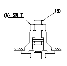
BCS adjustment procedure
1. At full boost pressure, set so that the full injection quantity is within the specifications (adjusting point).
2. Perform boost compensator intermediate operation point adjustment (pump speed N1, boost pressure P1).
3. When injection quantity at boost pressure P2 and pump speed N2 is not as specified, loosen nut (A) and adjust position of screw (B) so that injection quantity is as specified. The screw position should be within +-1 turn of initial position.
4. The nut tightening torque is T.
----------
N1=750r/min N2=750r/min P1=43.3kPa(325mmHg) P2=0kPa(0mmHg) T=6~9Nm(0.6~0.9kgfm)
----------
----------
N1=750r/min N2=750r/min P1=43.3kPa(325mmHg) P2=0kPa(0mmHg) T=6~9Nm(0.6~0.9kgfm)
----------
0000001801 CONTROL STANDARD AT IDLING
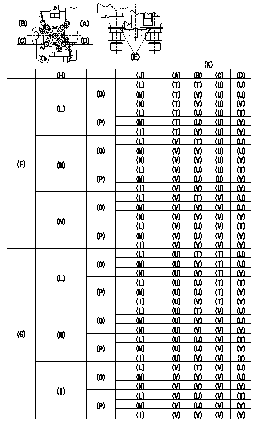
Standards for idle difference in delivery control
After idle adjustment, measure the idle injection quantities of (A) to (D).
Install the colored rings to the delivery valve holders (A) to (D) in accordance with the table.
(A): A cylinder (B) :B cylinder (C) : C cylinder (D): D cylinder
(E): Collar ring
(F): (A) >= (C)
(G): (C) > (A)
(H): (A) - (C) or (C) - (A)
(I): 0.2, 0.1(mm3/st)
(J): (B) - (D) or (D) - (B)
(K): Ring color
(L): At least 0.6 mm3/st
(M): 0.3, 0.4, 0.5 (mm3/st)
(N): 0.2, 0.1, 0.0 (mm3/st)
(O): (B) >= (D)
(P): (D) > (B)
(T): Yellow
(U): White
(V): Red
----------
----------
----------
----------
0000001901 POTENTIOMETER ADJUSTMENT
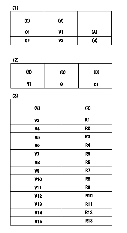
Adjustment of the potentiometer
(1)Potentiometer setting:
(A): Adjusting point
(B): Checking point
(C): Control lever opening
(V): P/N output voltage
C1:Full speed position
C2:Idling position
(2)Dummy bolt setting:
Fix the control lever with the dummy bolt so that the injection quantity is as shown in the following table at the pump speed = N1.
(N): Speed of the pump
(Q): Injection quantity
(D): Targeted lever angle
(3)Read the output voltage (V) of the potentiometer in the state indicated in (2) above. Then, select the compensation resistor from the following table and replace.
(R): Compensation resistance
Note
As the output voltage is compensated in the control unit after replacing the compensation resistor, confirmation is not necessary.
----------
N1=1000r/min
----------
N1=1000r/min Q1=24.8+-1.0mm3/st V1=8.16+-0.03V V2=2.33+-0.87V D1=(13.0deg) V3=3.73~3.84V V4=3.85~3.96V V5=3.97~4.08V V6=4.09~4.20V V7=4.21~4.32V V8=4.33~4.44V V9=4.45~4.56V V10=4.57~4.68V V11=4.69~4.80V V12=4.81~4.92V V13=4.93~5.04V V14=5.05~5.16V V15=5.17~5.28V R1=No.1,0.18(kohm) R2=No.2,0.30(kohm) R3=No.3,0.43(kohm) R4=No.4,0.62(kohm) R5=No.5,0.82(kohm) R6=No.6,1.10(kohm) R7=No.7,1.50(kohm) R8=No.8,2.00(kohm) R9=No.9,2.70(kohm) R10=No.10,3.90(kohm) R11=No.11,5.60(kohm) R12=No.12,8.20(kohm) R13=No.13,15.0(kohm)
----------
N1=1000r/min
----------
N1=1000r/min Q1=24.8+-1.0mm3/st V1=8.16+-0.03V V2=2.33+-0.87V D1=(13.0deg) V3=3.73~3.84V V4=3.85~3.96V V5=3.97~4.08V V6=4.09~4.20V V7=4.21~4.32V V8=4.33~4.44V V9=4.45~4.56V V10=4.57~4.68V V11=4.69~4.80V V12=4.81~4.92V V13=4.93~5.04V V14=5.05~5.16V V15=5.17~5.28V R1=No.1,0.18(kohm) R2=No.2,0.30(kohm) R3=No.3,0.43(kohm) R4=No.4,0.62(kohm) R5=No.5,0.82(kohm) R6=No.6,1.10(kohm) R7=No.7,1.50(kohm) R8=No.8,2.00(kohm) R9=No.9,2.70(kohm) R10=No.10,3.90(kohm) R11=No.11,5.60(kohm) R12=No.12,8.20(kohm) R13=No.13,15.0(kohm)
0000002001 WIRE
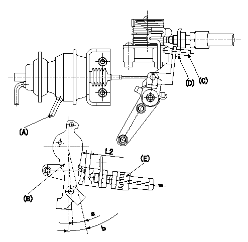
(1)Confirmation of the wire length:
Accelerator wire: Idle-full stroke: L1
(2)Confirmation on the idle SW
Confirm that the switch is ON at the idle lever position.
(3)Adjustment of the double stage actuator:
1. Apply negative pressure P1 to the actuator through the negative pressure suction inlet.
2. Under the conditions in 1. above, adjust using screw (C) so that the control lever () position is angle a [clearance L2+-0.5mm from idle switch (E)], and fix using the nut (D). (Tightening torque T)
b:Angle alpha
----------
L1=30.1+-4.0mm L2=3.8mm a=9deg P1=-66.6kPa(-500mmHg) T=6~9Nm(0.6~0.9kgfm)
----------
a=9deg b=12.5+-4deg L2=(3.8mm)
----------
L1=30.1+-4.0mm L2=3.8mm a=9deg P1=-66.6kPa(-500mmHg) T=6~9Nm(0.6~0.9kgfm)
----------
a=9deg b=12.5+-4deg L2=(3.8mm)
Information:
start by:a) remove flywheel 1. Disconnect oil line (1) from the BrakeSaver housing. 2. Remove the bolts and disconnect flanges (2) from the housing. 3. Remove four bolts, manifold (3) and the gasket from the bottom of the BrakeSaver housing. 4. Install tooling (A) on the BrakeSaver housing and rotor. This prevents damage to the rotor and seals when the BrakeSaver is removed. 5. Disconnect two air lines (4) and (5) at the air compressor. 6. Install tooling (B) and fasten a hoist to it. 7. Remove three bolts (6) from the BrakeSaver housing.8. Install two 3/8"-16 NC forcing screws (7) and remove the BrakeSaver. The weight of the BrakeSaver is 168 lb. (76 kg).Install BrakeSaver
1. Install tooling (B) on the BrakeSaver.2. Install two 5/8"-11 NC x 15" guide bolts (1).3. Put BrakeSaver (3) in position with the use of tooling (A) and a hoist.4. Make an alignment of dowel (2) in the crankshaft and the hole in the BrakeSaver. 5. Connect two air lines (4) and (5) to the air compressor. 6. Put O-ring seals (6) and (8) in position on the manifold.7. Put manifold (7) in position and install the bolts. 8. Put the gaskets and manifolds (9) in position and install the bolts. 9. Connect oil line (10) to the BrakeSaver housing.Disassemble BrakeSaver
start by:a) remove BrakeSaver1. Remove tool (A) from the BrakeSaver rotor and housing. Tool (A) prevents damage to the rotor seals and rings at removal of the BrakeSaver. 2. Remove bolts (1) from gear plate (2). Remove the plate. 3. Make identification as to the location of stator (3) with housing (4). Remove bolts (5) and the stator. 4. Turn the stator over and remove spiral ring (6). 5. Turn the stator over again. Remove sleeve assembly (9). Remove O-ring seal (7) and lip type seal (8) from the sleeve. 6. Remove seal (11) from around the housing and the six smaller seals from the oil lines.7. Remove rotor assembly (12).8. Remove seal ring (10) from both sides of the rotor. 9. Remove carrier (13) and wear sleeve (14) with tooling (B) from both sides of the rotor. 10. Remove spiral ring (15). Turn the housing over and remove sleeve assembly (17). Remove the lip type seal and O-ring seal (16) from the sleeve.Assemble Brakesaver
1. Put clean SAE 30 engine oil on the O-ring seal. Install seal (2) on sleeve (1).2. Install the sleeve in the BrakeSaver housing. Make alignment of the notch in the sleeve with the notch in the housing and install the dowel.3. Turn the housing over and install the spiral ring that holds the sleeve in the housing.
Make certain there is clearance behind the spiral ring when it is correctly installed.
4. Heat the carriers and the wear sleeves to a maximum temperature of 300°F (149°C). 5. Install carrier (5) on each side of rotor (3). Install wear sleeve (4) with the taper edge of sleeve in the "UP" position. Make sure the carrier is at bottom on the rotor