Information injection-pump assembly
BOSCH
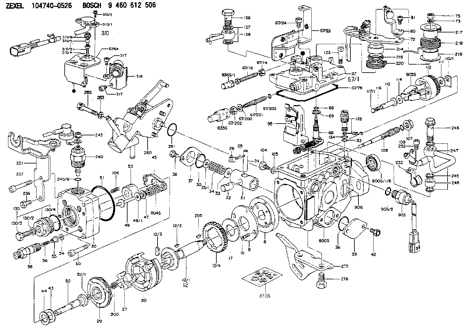
9 460 612 506
9460612506
ZEXEL
104740-0526
1047400526
MAZDA
PN6413800D
pn6413800d
Rating:
Components :
| 0. | INJECTION-PUMP ASSEMBLY | 104740-0526 |
| 1. | _ | |
| 2. | FUEL INJECTION PUMP | 104640-0526 |
| 3. | NUMBER PLATE | 146963-4900 |
| 4. | _ | 146672-5520 |
| 5. | CAPSULE | |
| 6. | ADJUSTING DEVICE | |
| 7. | NOZZLE AND HOLDER ASSY | 105148-1183 |
| 8. | Nozzle and Holder | PN40 13 H50C |
| 9. | Open Pre:MPa(Kqf/cm2) | 10.8{110} |
| 10. | NOZZLE-HOLDER | 105078-0111 |
| 11. | NOZZLE | 105007-1210 |
Scheme ###:
| 1/6. | [1] | 146601-0700 | PACKING RING |
| 6. | [1] | 146100-0120 | SUPPLY PUMP |
| 9. | [1] | 146103-0000 | COVER |
| 10. | [2] | 139104-0000 | FLAT-HEAD SCREW |
| 12. | [1] | 146200-0720 | DRIVE SHAFT |
| 12/1. | [1] | 146200-0300 | DRIVE SHAFT |
| 12/2. | [1] | 146201-0000 | WOODRUFF KEY |
| 12/3. | [2] | 146202-0100 | DAMPER |
| 12/4. | [1] | 146203-0000 | TOOTHED GEAR |
| 17. | [1] | 146204-0000 | PLAIN WASHER |
| 20. | [1] | 146210-4220 | ROLLER SET |
| 24. | [1] | 146303-0100 | BEARING PIN |
| 25. | [1] | 146304-0000 | BEARING PIN |
| 26. | [1] | 146305-0000 | CLAMPING BAND |
| 27. | [1] | 146205-0000 | SLOTTED WASHER |
| 29. | [1] | 146220-4120 | CAM PLATE |
| 30. | [1] | 146600-0800 | O-RING |
| 31. | [1] | 146300-3900 | PUMP PLUNGER |
| 32. | [1] | 146301-0400 | SLIDING PIECE |
| 33. | [1] | 146603-0700 | SHIM D17.5&7.5T0.60 |
| 34. | [1] | 146302-8400 | COMPRESSION SPRING |
| 34B. | [1] | 146302-8800 | COMPRESSION SPRING |
| 34C. | [1] | 146302-8100 | COMPRESSION SPRING |
| 35/1. | [0] | 146603-0700 | SHIM D17.5&7.5T0.60 |
| 35/1. | [0] | 146603-0800 | SHIM D17.5&7.5T0.70 |
| 35/1. | [0] | 146603-0900 | SHIM D17.5&7.5T0.90 |
| 35/1. | [0] | 146603-1000 | SHIM D17.5&7.5T1.00 |
| 35/1. | [0] | 146603-1100 | SHIM D17.5&7.5T1.20 |
| 35/1. | [0] | 146603-3600 | SHIM D17.5&7.5T2.40 |
| 36. | [1] | 146600-0800 | O-RING |
| 37. | [1] | 146310-0700 | COVER |
| 38. | [2] | 146620-5000 | BLEEDER SCREW |
| 39. | [1] | 146310-0100 | COVER |
| 40. | [2] | 146620-5000 | BLEEDER SCREW |
| 43. | [1] | 146230-0000 | SHIM |
| 44. | [1] | 146230-0100 | PLAIN WASHER |
| 45. | [1] | 146231-0001 | SLOTTED WASHER |
| 47. | [2] | 146233-0000 | SLOTTED WASHER |
| 48/1. | [1] | 146603-0000 | SHIM D17.0&5.2T0.50 |
| 48/1. | [1] | 146603-0100 | SHIM D17.0&5.2T0.80 |
| 48/1. | [1] | 146603-0200 | SHIM D17.0&5.2T1.00 |
| 48/1. | [1] | 146603-0300 | SHIM D17.0&5.2T1.20 |
| 48/1. | [1] | 146603-0400 | SHIM D17.0&5.2T1.50 |
| 48/1. | [1] | 146603-0500 | SHIM D17.0&5.2T1.80 |
| 48/1. | [1] | 146603-0600 | SHIM D17.0&5.2T2.00 |
| 48/1. | [1] | 146690-1400 | SHIM D17&5.2T0.9 |
| 48/1. | [1] | 146690-1500 | SHIM D17&5.2T1.1 |
| 48/1. | [1] | 146690-1600 | SHIM D17&5.2T1.3 |
| 48/1. | [1] | 146690-1700 | SHIM D17&5.2T1.4 |
| 48/1. | [1] | 146690-1800 | SHIM D17&5.2T1.6 |
| 48/1. | [1] | 146690-1900 | SHIM D17&5.2T1.7 |
| 48/1. | [1] | 146690-5800 | SHIM |
| 48/1. | [1] | 146690-5900 | SHIM |
| 48/1. | [1] | 146690-6000 | SHIM |
| 48/1. | [1] | 146690-6100 | SHIM |
| 48/1. | [1] | 146690-6200 | SHIM |
| 48/1. | [1] | 146690-6300 | SHIM |
| 48/1. | [1] | 146690-6400 | SHIM |
| 48/1. | [1] | 146690-6500 | SHIM |
| 48/1. | [1] | 146690-6600 | SHIM |
| 48/1. | [1] | 146690-6700 | SHIM |
| 48/1. | [1] | 146690-6800 | SHIM |
| 48/1. | [1] | 146690-6900 | SHIM |
| 48/1. | [1] | 146690-7000 | SHIM |
| 48/1. | [1] | 146690-7100 | SHIM |
| 48/1. | [1] | 146690-7200 | SHIM |
| 48/1. | [1] | 146690-7300 | SHIM |
| 48/1. | [1] | 146690-7400 | SHIM |
| 48/1. | [1] | 146690-7500 | SHIM |
| 48/1. | [1] | 146690-7800 | SHIM |
| 49. | [2] | 146234-0120 | GUIDE PIN |
| 50. | [1] | 146403-2820 | HYDRAULIC HEAD |
| 50. | [1] | 146403-2820 | HYDRAULIC HEAD |
| 50. | [1] | 146403-2820 | HYDRAULIC HEAD |
| 51. | [1] | 146600-0000 | O-RING |
| 52/1. | [1] | 146420-0000 | SHIM D9.5&3.0T1.90 |
| 52/1. | [1] | 146420-0100 | SHIM D9.5&3.0T1.92 |
| 52/1. | [1] | 146420-0200 | SHIM D9.5&3.0T1.94 |
| 52/1. | [1] | 146420-0300 | SHIM D9.5&3.0T1.96 |
| 52/1. | [1] | 146420-0400 | SHIM D9.5&3.0T1.98 |
| 52/1. | [1] | 146420-0500 | SHIM D9.5&3.0T2.00 |
| 52/1. | [1] | 146420-0600 | SHIM D9.5&3.0T2.02 |
| 52/1. | [1] | 146420-0700 | SHIM D9.5&3.0T2.04 |
| 52/1. | [1] | 146420-0800 | SHIM D9.5&3.0T2.06 |
| 52/1. | [1] | 146420-0900 | SHIM D9.5&3.0T2.08 |
| 52/1. | [1] | 146420-1000 | SHIM D9.5&3.0T2.10 |
| 52/1. | [1] | 146420-1100 | SHIM D9.5&3.0T2.12 |
| 52/1. | [1] | 146420-1200 | SHIM D9.5&3.0T2.14 |
| 52/1. | [1] | 146420-1300 | SHIM D9.5&3.0T2.16 |
| 52/1. | [1] | 146420-1400 | SHIM D9.5&3.0T2.18 |
| 52/1. | [1] | 146420-1500 | SHIM D9.5&3.0T2.20 |
| 52/1. | [1] | 146420-1600 | SHIM D9.5&3.0T2.22 |
| 52/1. | [1] | 146420-1700 | SHIM D9.5&3.0T2.24 |
| 52/1. | [1] | 146420-1800 | SHIM D9.5&3.0T2.26 |
| 52/1. | [1] | 146420-1900 | SHIM D9.5&3.0T2.28 |
| 52/1. | [1] | 146420-2000 | SHIM D9.5&3.0T2.30 |
| 52/1. | [1] | 146420-2100 | SHIM D9.5&3.0T2.32 |
| 52/1. | [1] | 146420-2200 | SHIM D9.5&3.0T2.34 |
| 52/1. | [1] | 146420-2300 | SHIM D9.5&3.0T2.36 |
| 52/1. | [1] | 146420-2400 | SHIM D9.5&3.0T2.38 |
| 52/1. | [1] | 146420-2500 | SHIM D9.5&3.0T2.40 |
| 52/1. | [1] | 146420-2600 | SHIM D9.5&3.0T2.42 |
| 52/1. | [1] | 146420-2700 | SHIM D9.5&3.0T2.44 |
| 52/1. | [1] | 146420-2800 | SHIM D9.5&3.0T2.46 |
| 52/1. | [1] | 146420-2900 | SHIM D9.5&3.0T2.48 |
| 52/1. | [1] | 146420-3000 | SHIM D9.5&3.0T2.50 |
| 52/1. | [1] | 146420-3100 | SHIM D9.5&3.0T2.52 |
| 52/1. | [1] | 146420-3200 | SHIM D9.5&3.0T2.54 |
| 52/1. | [1] | 146420-3300 | SHIM D9.5&3.0T2.56 |
| 52/1. | [1] | 146420-3400 | SHIM D9.5&3.0T2.58 |
| 52/1. | [1] | 146420-3500 | SHIM D9.5&3.0T2.60 |
| 52/1. | [1] | 146420-3600 | SHIM D9.5&3.0T2.62 |
| 52/1. | [1] | 146420-3700 | SHIM D9.5&3.0T2.64 |
| 52/1. | [1] | 146420-3800 | SHIM D9.5&3.0T2.66 |
| 52/1. | [1] | 146420-3900 | SHIM D9.5&3.0T2.68 |
| 52/1. | [1] | 146420-4000 | SHIM D9.5&3.0T2.70 |
| 52/1. | [1] | 146420-4100 | SHIM D9.5&3.0T2.72 |
| 52/1. | [1] | 146420-4200 | SHIM D9.5&3.0T2.74 |
| 52/1. | [1] | 146420-4300 | SHIM D9.5&3.0T2.76 |
| 52/1. | [1] | 146420-4400 | SHIM D9.5&3.0T2.78 |
| 52/1. | [1] | 146420-4500 | SHIM D9.5&3.0T2.80 |
| 52/1. | [1] | 146420-4600 | SHIM D9.5&3.0T2.82 |
| 52/1. | [1] | 146420-4700 | SHIM D9.5&3.0T2.84 |
| 52/1. | [1] | 146420-4800 | SHIM D9.5&3.0T2.86 |
| 52/1. | [1] | 146420-4900 | SHIM D9.5&3.0T2.88 |
| 52/1. | [1] | 146420-5000 | SHIM D9.5&3.0T2.90 |
| 52/1. | [1] | 146420-5100 | SHIM D9.5&3.0T1.74 |
| 52/1. | [1] | 146420-5200 | SHIM D9.5&3.0T1.76 |
| 52/1. | [1] | 146420-5300 | SHIM D9.5&3.0T1.78 |
| 52/1. | [1] | 146420-5400 | SHIM D9.5&3.0T1.80 |
| 52/1. | [1] | 146420-5500 | SHIM D9.5&3.0T1.82 |
| 52/1. | [1] | 146420-5600 | SHIM D9.5&3.0T1.84 |
| 52/1. | [1] | 146420-5700 | SHIM D9.5&3.0T1.86 |
| 52/1. | [1] | 146420-5800 | SHIM D9.5&3.0T1.88 |
| 54. | [4] | 146433-0100 | GASKET D12&6.4T1.00 |
| 55. | [4] | 146430-3420 | DELIVERY-VALVE ASSEMBLY |
| 56. | [4] | 146432-0000 | COMPRESSION SPRING |
| 58. | [4] | 146440-0220 | FITTING |
| 60. | [3] | 139106-0100 | FLAT-HEAD SCREW |
| 66. | [1] | 146600-0100 | O-RING |
| 67. | [1] | 146503-7221 | GOVERNOR COVER |
| 67/1. | [1] | 146508-4921 | GOVERNOR COVER |
| 67/14. | [1] | 146621-1700 | UNION NUT |
| 67/16. | [1] | 146526-2800 | BLEEDER SCREW |
| 67/23. | [1] | 146930-0120 | BRACKET |
| 67/24. | [2] | 010206-1040 | HEX-SOCKET-HEAD CAP SCREW |
| 67/64. | [1] | 146930-0020 | BRACKET |
| 67/78. | [1] | 146600-4400 | SEAL RING |
| 67/200. | [1] | 139308-0300 | PLAIN WASHER |
| 67/201. | [1] | 146545-4100 | THREADED PIN |
| 67/201B. | [1] | 146545-4200 | THREADED PIN |
| 67/201C. | [1] | 146545-4300 | THREADED PIN |
| 67/202. | [1] | 139208-0900 | UNION NUT |
| 67/203. | [1] | 146600-1200 | O-RING |
| 68. | [1] | 146513-8920 | CONTROL SHAFT |
| 69. | [1] | 139310-0200 | PLAIN WASHER |
| 72. | [1] | 146539-9020 | CONTROL LEVER |
| 72B. | [1] | 146539-9120 | CONTROL LEVER |
| 73. | [1] | 014110-6440 | LOCKING WASHER |
| 75. | [1] | 146621-0700 | UNION NUT |
| 80. | [1] | 146539-9420 | CONTROL LEVER |
| 81. | [2] | 020105-1040 | BLEEDER SCREW M5P0.8L10 |
| 95. | [1] | 146851-0220 | FULCRUM LEVER |
| 104. | [2] | 146568-0000 | SLOTTED SPRING PIN |
| 105. | [2] | 026508-1140 | GASKET D11.4&8.2T1 |
| 106. | [2] | 146588-0500 | COILED SPRING |
| 107. | [1] | 146569-0300 | UNION NUT |
| 108. | [1] | 146570-0420 | GOVERNOR SHAFT |
| 109. | [1] | 146600-0400 | O-RING |
| 110/1. | [1] | 146571-0000 | SHIM D20.2&8.3T1.05 |
| 110/1. | [1] | 146571-0100 | SHIM D20.2&8.3T1.25 |
| 110/1. | [1] | 146571-0200 | SHIM D20.2&8.3T1.45 |
| 110/1. | [1] | 146571-0300 | SHIM D20.2&8.3T1.65 |
| 110/1. | [1] | 146571-0400 | SHIM D20.2&8.3T1.85 |
| 110/1. | [1] | 146571-0500 | SHIM D20.2&8.3T1.15 |
| 110/1. | [1] | 146571-0600 | SHIM D20.2&8.3T1.35 |
| 110/1. | [1] | 146571-0700 | SHIM D20.2&8.3T1.55 |
| 110/1. | [1] | 146571-0800 | SHIM D20.2&8.3T1.75 |
| 111. | [1] | 146602-0600 | PLAIN WASHER D20&8.4T1.40 |
| 112. | [1] | 146572-0020 | FLYWEIGHT ASSEMBLY |
| 114. | [1] | 146602-0500 | PLAIN WASHER D17&6.4T1.60 |
| 115. | [1] | 146875-7300 | SLIDING SLEEVE |
| 116. | [1] | 146576-0200 | CAP |
| 117/1. | [1] | 146577-1800 | PLUG L2.10 |
| 117/1. | [1] | 146577-1900 | PLUG L2.30 |
| 117/1. | [1] | 146577-2000 | PLUG L2.50 |
| 117/1. | [1] | 146577-2100 | PLUG L2.70 |
| 117/1. | [1] | 146577-2200 | PLUG L2.90 |
| 117/1. | [1] | 146577-2300 | PLUG L3.10 |
| 117/1. | [1] | 146577-2400 | PLUG L3.30 |
| 117/1. | [1] | 146577-2500 | PLUG L3.50 |
| 117/1. | [1] | 146577-2600 | PLUG L3.70 |
| 117/1. | [1] | 146577-2700 | PLUG L3.90 |
| 117/1. | [1] | 146577-2800 | PLUG L4.10 |
| 117/1. | [1] | 146577-2900 | PLUG L4.30 |
| 117/1. | [1] | 146577-3000 | PLUG L4.50 |
| 117/1. | [1] | 146577-3100 | PLUG L4.70 |
| 117/1. | [1] | 146577-3200 | PLUG L4.90 |
| 117/1. | [1] | 146577-3300 | PLUG L5.10 |
| 117/1. | [1] | 146577-6700 | PLUG L2.2 |
| 117/1. | [1] | 146577-6800 | PLUG L2.4 |
| 117/1. | [1] | 146577-6900 | PLUG L2.6 |
| 117/1. | [1] | 146577-7000 | PLUG L2.8 |
| 117/1. | [1] | 146577-7100 | PLUG L3.0 |
| 117/1. | [1] | 146577-7200 | PLUG L3.2 |
| 117/1. | [1] | 146577-7300 | PLUG L3.4 |
| 117/1. | [1] | 146577-7400 | PLUG L3.6 |
| 117/1. | [1] | 146577-7500 | PLUG L3.8 |
| 117/1. | [1] | 146577-7600 | PLUG L4.0 |
| 117/1. | [1] | 146577-7700 | PLUG L4.2 |
| 117/1. | [1] | 146577-7800 | PLUG L4.4 |
| 117/1. | [1] | 146577-7900 | PLUG L4.6 |
| 117/1. | [1] | 146577-8000 | PLUG L4.8 |
| 117/1. | [1] | 146577-8100 | PLUG L5.0 |
| 117/1. | [1] | 146877-0000 | PLUG L5.2 |
| 117/1. | [1] | 146877-0100 | PLUG L5.3 |
| 117/1. | [1] | 146877-0200 | PLUG L5.4 |
| 117/1. | [1] | 146877-0300 | PLUG L5.5 |
| 117/1. | [1] | 146877-4700 | PLUG |
| 117/1. | [1] | 146877-4800 | PLUG |
| 117/1. | [1] | 146877-4900 | PLUG |
| 117/1. | [1] | 146877-5000 | PLUG |
| 123. | [4] | 139106-0200 | FLAT-HEAD SCREW |
| 130. | [1] | 146421-0020 | CAPSULE |
| 130/2. | [1] | 026508-1140 | GASKET D11.4&8.2T1 |
| 130/3. | [1] | 146422-0000 | BLEEDER SCREW |
| 130/4. | [1] | 146600-0500 | O-RING |
| 133. | [1] | 146600-0600 | O-RING |
| 134. | [1] | 146600-0700 | O-RING |
| 135. | [1] | 146110-0220 | CONTROL VALVE |
| 135/5. | [1] | 146114-0000 | SPRING WASHER |
| 136. | [1] | 146120-1120 | OVER FLOW VALVE |
| 137. | [2] | 139512-0500 | GASKET |
| 138. | [1] | 146608-3220 | INLET UNION |
| 200. | [1] | 146206-0100 | COILED SPRING |
| 205. | [1] | 029470-4030 | WOODRUFF KEY |
| 214. | [1] | 146542-1400 | BUSHING |
| 215. | [1] | 146542-1500 | BUSHING |
| 217. | [1] | 146542-5700 | SLOTTED WASHER |
| 218. | [1] | 146592-4500 | COILED SPRING |
| 219. | [1] | 146541-3000 | BUSHING |
| 220. | [1] | 146592-4600 | COILED SPRING |
| 221. | [1] | 146928-9320 | BRACKET |
| 232. | [1] | 146659-3600 | CLAMPING BAND |
| 236. | [1] | 139006-4800 | BLEEDER SCREW |
| 237. | [1] | 146620-0200 | HEX-SOCKET-HEAD CAP SCREW |
| 240. | [1] | 146650-4320 | PULLING ELECTROMAGNET |
| 240/8. | [1] | 146600-1700 | O-RING |
| 243. | [1] | 146621-1000 | UNION NUT |
| 245. | [3] | 139512-0500 | GASKET |
| 246. | [1] | 139812-1900 | EYE BOLT |
| 247. | [1] | 146665-3520 | INLET UNION |
| 248. | [1] | 146614-0200 | SPACER BUSHING |
| 252. | [1] | 010206-1040 | HEX-SOCKET-HEAD CAP SCREW |
| 275. | [1] | 146612-6100 | BRACKET |
| 276. | [2] | 010010-1640 | BLEEDER SCREW M10P1.5L16 4T |
| 280. | [1] | 146361-3022 | START ADVANCE ASSY |
| 281. | [1] | 146600-0800 | O-RING |
| 282. | [1] | 020106-3040 | BLEEDER SCREW |
| 283. | [1] | 014010-6140 | PLAIN WASHER D13&6.5T1 |
| 310. | [1] | 146683-5321 | POTENTCIOMETER |
| 310/1. | [1] | 146683-1911 | POTENTCIOMETER |
| 310/2. | [2] | 139104-0400 | FLAT-HEAD SCREW |
| 310/3. | [1] | 146620-1500 | FLAT-HEAD SCREW |
| 310/4. | [1] | 013020-6040 | UNION NUT M6P1H5 |
| 310/5. | [1] | 146614-2300 | JOINT CONNECTION |
| 310/6. | [1] | 146661-0401 | BOOT |
| 316. | [1] | 146680-4920 | DAMPER |
| 317. | [2] | 010206-1040 | HEX-SOCKET-HEAD CAP SCREW |
| 317. | [2] | 010206-1040 | HEX-SOCKET-HEAD CAP SCREW |
| 800S. | [1] | 146019-8920 | PUMP HOUSING |
| 800S/1/6. | [1] | 146601-0700 | PACKING RING |
| 804S. | [1] | 146232-0720 | COMPRESSION SPRING |
| 805S. | [1] | 146574-0120 | PARTS SET |
| 810S. | [1] | 146600-2420 | REPAIR SET |
| 835S. | [1] | 146598-1000 | CAP |
| 836S/1. | [1] | 146598-0600 | CAP L18 |
| 836S/1. | [1] | 146598-0700 | CAP L21 |
| 836S/1. | [1] | 146598-0800 | CAP L24 |
| 836S/1. | [1] | 146598-0900 | CAP L27 |
| 903. | [1] | 146672-5520 | PULSE GENERATOR |
| 903/2. | [1] | 146600-1300 | O-RING &13W1.9 |
| 906. | [1] | 146963-4900 | NAMEPLATE |
Include in #2:
104740-0526
as INJECTION-PUMP ASSEMBLY
Cross reference number
Zexel num
Bosch num
Firm num
Name
9 460 612 506
PN6413800D MAZDA
INJECTION-PUMP ASSEMBLY
PN K 11CJ INJECTION PUMP ASSY VE4 VE
PN K 11CJ INJECTION PUMP ASSY VE4 VE
Information:
(1) Nut (4K0367)(2) Bearing (9U6877)(3) Washer (5P8247)(4) Bridge plate (9U7259)(5) Bolts (5/16)(6) Threaded rod puller stud (221-9778)(7) Threaded end
Install the remaining parts of Tool B on the threadedrod assembly (item 6).
Lubricate the threads on (item 6).
Tighten nut (item 1) in order to remove the unitinjector sleeve. Do not use an impact wrench.
After the sleeve is removed, use the large 4C5552wire brush to remove dirt and sealant from the bore. Squirt isopropyl alcoholor brake cleaner into the bore to remove oil. Use paper towels and swabsto remove all debris from the bore. Ensure the injector bore and fuel railare clean and free from debris.
Any sealant, fuel, oil or debris willprevent the sealant from properly curing. Improper cleaning will lead toa poor sealing surface and leak path.
Table 3 Unit Injector Sleeve ? InstallRequired Tools
ToolA
Part Number Description Quantity
2219777 Sleeve Installer 1
4C9507 Locktite 620 Sealant 1 Keep all parts clean from contaminants.Contaminants may cause rapid wear and shortened component life.
Ensure the o-ring (8T7878) is in place on the2219777 sleeve installer
Place the 1785037 unit injector sleeve on ToolA.
Clean the sleeve with isopropyl alcohol and wipedry with as clean paper towel. Note: Make sure the sleeve is free ofall debris, oil and fuel.
Apply 4C9507 Locktite 620 sealant (shake wellbefore using, sealant can separate) to the upper land and lower land ofthe unit injector sleeve.
Surfaces to be sealed must be freeof oil, grease, fuel, etc.
Install the unit injector sleeve into the injectorsleeve bore.
Use a hammer to drive the sleeve into the headuntil the sleeve bottoms out.
Wipe all excess anaerobic from the injector borewith a paper towel and swab.
Stamp AH on the front left top of the cylinderhead near the HEP 8 pump to verify the rework has been completed.
Wait approximately two (2) hours atroom temperature (70F) before filling the engine with fuel or coolant.Longer curing time is needed at lower temperatures.Unit injectors ? Installation procedure
Keep all parts clean from contaminants.Contaminants may cause rapid wear and shortened component life.
Part Number Description Quantity
Tool A 1492955 Seal Protector 1
Tool B 1492956 Seal Installer 1
Install injection actuation pressure sensor. Torquethe sensor to 10 2 N m (88 18 lb in).
Install the fuel lines and fittings as needed.Torque to specifications.
Lubricate the O-Ring seals and the sleeve boreof the injector sparingly with clean engine oil.
Install injector in the cylinder head. Positionthe injector into the cylinder head. Use your hand to install the injectorinto the cylinder head. Install socket head bolt on the exhaust side ofthe hold down bracket. Tighten the exhaust side of socket head bolt untilthe bolt is seated. Install and tighten the inlet side of socket head boltto a torque of 12 1 N m (9 1 lb ft).
Install the valve mechanism cover. Refer to Disassemblyand Assembly, "Valve Mechanism Cover - Remove and Install".
If the o-rings are damaged and needreplaced.
Use Tool (A) and Tool (B) to install the upper high-pressure seal pack.
Install the upper seal pack first. Then installthe middle seal pack. Finally, install the bottom O-Ring Seal.
Install Tool (A) on the injector.
Use Tool (B) to install backup rings and O-ringseal on the unit injector. Lubricate the O-ring seals and