Information injection-pump assembly
BOSCH
9 460 612 472
9460612472
ZEXEL
104740-0403
1047400403
MAZDA
PN4113800E
pn4113800e
Rating:
Components :
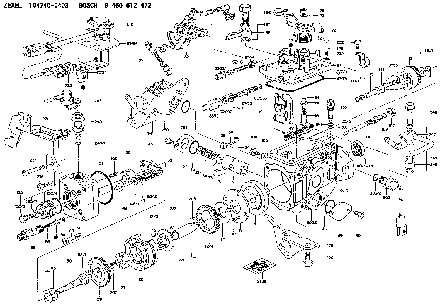
| 0. | INJECTION-PUMP ASSEMBLY | 104740-0403 |
| 1. | _ | |
| 2. | FUEL INJECTION PUMP | 104640-0403 |
| 3. | NUMBER PLATE | 146960-0300 |
| 4. | _ | 146672-5520 |
| 5. | CAPSULE | |
| 6. | ADJUSTING DEVICE | |
| 7. | NOZZLE AND HOLDER ASSY | 105148-1183 |
| 8. | Nozzle and Holder | PN40 13 H50C |
| 9. | Open Pre:MPa(Kqf/cm2) | 10.8{110} |
| 10. | NOZZLE-HOLDER | 105078-0111 |
| 11. | NOZZLE | 105007-1210 |
Scheme ###:
| 1/6. | [1] | 146601-0100 | PACKING RING |
| 6. | [1] | 146100-0120 | SUPPLY PUMP |
| 9. | [1] | 146103-0000 | COVER |
| 10. | [2] | 139104-0000 | FLAT-HEAD SCREW |
| 12. | [1] | 146200-0720 | DRIVE SHAFT |
| 12/1. | [1] | 146200-0300 | DRIVE SHAFT |
| 12/2. | [1] | 146201-0000 | WOODRUFF KEY |
| 12/3. | [2] | 146202-0100 | DAMPER |
| 12/4. | [1] | 146203-0000 | TOOTHED GEAR |
| 17. | [1] | 146204-0000 | PLAIN WASHER |
| 20. | [1] | 146210-2620 | ROLLER SET |
| 24. | [1] | 146303-0100 | BEARING PIN |
| 25. | [1] | 146304-0000 | BEARING PIN |
| 26. | [1] | 146305-0000 | CLAMPING BAND |
| 27. | [1] | 146205-0000 | SLOTTED WASHER |
| 29. | [1] | 146220-1320 | CAM PLATE |
| 30. | [1] | 146600-0800 | O-RING |
| 31. | [1] | 146300-3900 | PUMP PLUNGER |
| 32. | [1] | 146301-0200 | SLIDING PIECE |
| 33. | [1] | 146603-0700 | SHIM D17.5&7.5T0.60 |
| 34. | [1] | 146302-8400 | COMPRESSION SPRING |
| 34B. | [1] | 146302-8800 | COMPRESSION SPRING |
| 34C. | [1] | 146302-8100 | COMPRESSION SPRING |
| 35/1. | [0] | 146603-0700 | SHIM D17.5&7.5T0.60 |
| 35/1. | [0] | 146603-0800 | SHIM D17.5&7.5T0.70 |
| 35/1. | [0] | 146603-0900 | SHIM D17.5&7.5T0.90 |
| 35/1. | [0] | 146603-1000 | SHIM D17.5&7.5T1.00 |
| 35/1. | [0] | 146603-1100 | SHIM D17.5&7.5T1.20 |
| 35/1. | [0] | 146603-3600 | SHIM D17.5&7.5T2.40 |
| 36. | [1] | 146600-0800 | O-RING |
| 37. | [1] | 146310-0700 | COVER |
| 38. | [2] | 146620-5000 | BLEEDER SCREW |
| 39. | [1] | 146310-0100 | COVER |
| 40. | [2] | 146620-5000 | BLEEDER SCREW |
| 43. | [1] | 146230-0000 | SHIM |
| 44. | [1] | 146230-0100 | PLAIN WASHER |
| 45. | [1] | 146231-0000 | SLOTTED WASHER |
| 47. | [2] | 146233-0000 | SLOTTED WASHER |
| 48/1. | [1] | 146603-0000 | SHIM D17.0&5.2T0.50 |
| 48/1. | [1] | 146603-0100 | SHIM D17.0&5.2T0.80 |
| 48/1. | [1] | 146603-0200 | SHIM D17.0&5.2T1.00 |
| 48/1. | [1] | 146603-0300 | SHIM D17.0&5.2T1.20 |
| 48/1. | [1] | 146603-0400 | SHIM D17.0&5.2T1.50 |
| 48/1. | [1] | 146603-0500 | SHIM D17.0&5.2T1.80 |
| 48/1. | [1] | 146603-0600 | SHIM D17.0&5.2T2.00 |
| 48/1. | [1] | 146690-1400 | SHIM D17&5.2T0.9 |
| 48/1. | [1] | 146690-1500 | SHIM D17&5.2T1.1 |
| 48/1. | [1] | 146690-1600 | SHIM D17&5.2T1.3 |
| 48/1. | [1] | 146690-1700 | SHIM D17&5.2T1.4 |
| 48/1. | [1] | 146690-1800 | SHIM D17&5.2T1.6 |
| 48/1. | [1] | 146690-1900 | SHIM D17&5.2T1.7 |
| 48/1. | [1] | 146690-5800 | SHIM |
| 48/1. | [1] | 146690-5900 | SHIM |
| 48/1. | [1] | 146690-6000 | SHIM |
| 48/1. | [1] | 146690-6100 | SHIM |
| 48/1. | [1] | 146690-6200 | SHIM |
| 48/1. | [1] | 146690-6300 | SHIM |
| 48/1. | [1] | 146690-6400 | SHIM |
| 48/1. | [1] | 146690-6500 | SHIM |
| 48/1. | [1] | 146690-6600 | SHIM |
| 48/1. | [1] | 146690-6700 | SHIM |
| 48/1. | [1] | 146690-6800 | SHIM |
| 48/1. | [1] | 146690-6900 | SHIM |
| 48/1. | [1] | 146690-7000 | SHIM |
| 48/1. | [1] | 146690-7100 | SHIM |
| 48/1. | [1] | 146690-7200 | SHIM |
| 48/1. | [1] | 146690-7300 | SHIM |
| 48/1. | [1] | 146690-7400 | SHIM |
| 48/1. | [1] | 146690-7500 | SHIM |
| 48/1. | [1] | 146690-7800 | SHIM |
| 49. | [2] | 146234-0120 | GUIDE PIN |
| 50. | [1] | 146403-2820 | HYDRAULIC HEAD |
| 50. | [1] | 146403-2820 | HYDRAULIC HEAD |
| 50. | [1] | 146403-2820 | HYDRAULIC HEAD |
| 51. | [1] | 146600-0000 | O-RING |
| 52/1. | [1] | 146420-0000 | SHIM D9.5&3.0T1.90 |
| 52/1. | [1] | 146420-0100 | SHIM D9.5&3.0T1.92 |
| 52/1. | [1] | 146420-0200 | SHIM D9.5&3.0T1.94 |
| 52/1. | [1] | 146420-0300 | SHIM D9.5&3.0T1.96 |
| 52/1. | [1] | 146420-0400 | SHIM D9.5&3.0T1.98 |
| 52/1. | [1] | 146420-0500 | SHIM D9.5&3.0T2.00 |
| 52/1. | [1] | 146420-0600 | SHIM D9.5&3.0T2.02 |
| 52/1. | [1] | 146420-0700 | SHIM D9.5&3.0T2.04 |
| 52/1. | [1] | 146420-0800 | SHIM D9.5&3.0T2.06 |
| 52/1. | [1] | 146420-0900 | SHIM D9.5&3.0T2.08 |
| 52/1. | [1] | 146420-1000 | SHIM D9.5&3.0T2.10 |
| 52/1. | [1] | 146420-1100 | SHIM D9.5&3.0T2.12 |
| 52/1. | [1] | 146420-1200 | SHIM D9.5&3.0T2.14 |
| 52/1. | [1] | 146420-1300 | SHIM D9.5&3.0T2.16 |
| 52/1. | [1] | 146420-1400 | SHIM D9.5&3.0T2.18 |
| 52/1. | [1] | 146420-1500 | SHIM D9.5&3.0T2.20 |
| 52/1. | [1] | 146420-1600 | SHIM D9.5&3.0T2.22 |
| 52/1. | [1] | 146420-1700 | SHIM D9.5&3.0T2.24 |
| 52/1. | [1] | 146420-1800 | SHIM D9.5&3.0T2.26 |
| 52/1. | [1] | 146420-1900 | SHIM D9.5&3.0T2.28 |
| 52/1. | [1] | 146420-2000 | SHIM D9.5&3.0T2.30 |
| 52/1. | [1] | 146420-2100 | SHIM D9.5&3.0T2.32 |
| 52/1. | [1] | 146420-2200 | SHIM D9.5&3.0T2.34 |
| 52/1. | [1] | 146420-2300 | SHIM D9.5&3.0T2.36 |
| 52/1. | [1] | 146420-2400 | SHIM D9.5&3.0T2.38 |
| 52/1. | [1] | 146420-2500 | SHIM D9.5&3.0T2.40 |
| 52/1. | [1] | 146420-2600 | SHIM D9.5&3.0T2.42 |
| 52/1. | [1] | 146420-2700 | SHIM D9.5&3.0T2.44 |
| 52/1. | [1] | 146420-2800 | SHIM D9.5&3.0T2.46 |
| 52/1. | [1] | 146420-2900 | SHIM D9.5&3.0T2.48 |
| 52/1. | [1] | 146420-3000 | SHIM D9.5&3.0T2.50 |
| 52/1. | [1] | 146420-3100 | SHIM D9.5&3.0T2.52 |
| 52/1. | [1] | 146420-3200 | SHIM D9.5&3.0T2.54 |
| 52/1. | [1] | 146420-3300 | SHIM D9.5&3.0T2.56 |
| 52/1. | [1] | 146420-3400 | SHIM D9.5&3.0T2.58 |
| 52/1. | [1] | 146420-3500 | SHIM D9.5&3.0T2.60 |
| 52/1. | [1] | 146420-3600 | SHIM D9.5&3.0T2.62 |
| 52/1. | [1] | 146420-3700 | SHIM D9.5&3.0T2.64 |
| 52/1. | [1] | 146420-3800 | SHIM D9.5&3.0T2.66 |
| 52/1. | [1] | 146420-3900 | SHIM D9.5&3.0T2.68 |
| 52/1. | [1] | 146420-4000 | SHIM D9.5&3.0T2.70 |
| 52/1. | [1] | 146420-4100 | SHIM D9.5&3.0T2.72 |
| 52/1. | [1] | 146420-4200 | SHIM D9.5&3.0T2.74 |
| 52/1. | [1] | 146420-4300 | SHIM D9.5&3.0T2.76 |
| 52/1. | [1] | 146420-4400 | SHIM D9.5&3.0T2.78 |
| 52/1. | [1] | 146420-4500 | SHIM D9.5&3.0T2.80 |
| 52/1. | [1] | 146420-4600 | SHIM D9.5&3.0T2.82 |
| 52/1. | [1] | 146420-4700 | SHIM D9.5&3.0T2.84 |
| 52/1. | [1] | 146420-4800 | SHIM D9.5&3.0T2.86 |
| 52/1. | [1] | 146420-4900 | SHIM D9.5&3.0T2.88 |
| 52/1. | [1] | 146420-5000 | SHIM D9.5&3.0T2.90 |
| 52/1. | [1] | 146420-5100 | SHIM D9.5&3.0T1.74 |
| 52/1. | [1] | 146420-5200 | SHIM D9.5&3.0T1.76 |
| 52/1. | [1] | 146420-5300 | SHIM D9.5&3.0T1.78 |
| 52/1. | [1] | 146420-5400 | SHIM D9.5&3.0T1.80 |
| 52/1. | [1] | 146420-5500 | SHIM D9.5&3.0T1.82 |
| 52/1. | [1] | 146420-5600 | SHIM D9.5&3.0T1.84 |
| 52/1. | [1] | 146420-5700 | SHIM D9.5&3.0T1.86 |
| 52/1. | [1] | 146420-5800 | SHIM D9.5&3.0T1.88 |
| 54. | [4] | 146433-0100 | GASKET D12&6.4T1.00 |
| 55. | [4] | 146430-3420 | DELIVERY-VALVE ASSEMBLY |
| 56. | [4] | 146432-0000 | COMPRESSION SPRING |
| 58. | [4] | 146440-0220 | FITTING |
| 60. | [3] | 139106-0100 | FLAT-HEAD SCREW |
| 66. | [1] | 146600-0100 | O-RING |
| 67. | [1] | 146503-4821 | GOVERNOR COVER |
| 67/1. | [1] | 146508-4921 | GOVERNOR COVER |
| 67/14. | [1] | 146621-1700 | UNION NUT |
| 67/16. | [1] | 146526-2800 | BLEEDER SCREW |
| 67/24. | [4] | 010206-1040 | HEX-SOCKET-HEAD CAP SCREW |
| 67/64. | [1] | 146927-5800 | BRACKET |
| 67/78. | [1] | 146600-1000 | SEAL RING |
| 67/200. | [1] | 139308-0300 | PLAIN WASHER |
| 67/201. | [1] | 146545-3400 | THREADED PIN L53.00 |
| 67/201B. | [1] | 146545-3500 | THREADED PIN L55.00 |
| 67/201C. | [1] | 146545-3600 | THREADED PIN L57.00 |
| 67/202. | [1] | 139208-0900 | UNION NUT |
| 67/203. | [1] | 146600-1200 | O-RING |
| 68. | [1] | 146513-8920 | CONTROL SHAFT |
| 69. | [1] | 139310-0200 | PLAIN WASHER |
| 72. | [1] | 146536-7200 | CONTROL LEVER |
| 72B. | [1] | 146536-7300 | CONTROL LEVER |
| 73. | [1] | 014110-6440 | LOCKING WASHER |
| 75. | [1] | 146621-0700 | UNION NUT |
| 78. | [1] | 146549-8720 | CONTROL LEVER |
| 80. | [1] | 146547-8220 | CONTROL LEVER |
| 85. | [1] | 146549-7520 | RACK |
| 95. | [1] | 146851-0220 | FULCRUM LEVER |
| 104. | [2] | 146568-0000 | SLOTTED SPRING PIN |
| 105. | [2] | 026508-1140 | GASKET D11.4&8.2T1 |
| 106. | [2] | 146588-0500 | COILED SPRING |
| 107. | [1] | 146569-0300 | UNION NUT |
| 108. | [1] | 146570-0420 | GOVERNOR SHAFT |
| 109. | [1] | 146600-0400 | O-RING |
| 110/1. | [1] | 146571-0000 | SHIM D20.2&8.3T1.05 |
| 110/1. | [1] | 146571-0100 | SHIM D20.2&8.3T1.25 |
| 110/1. | [1] | 146571-0200 | SHIM D20.2&8.3T1.45 |
| 110/1. | [1] | 146571-0300 | SHIM D20.2&8.3T1.65 |
| 110/1. | [1] | 146571-0400 | SHIM D20.2&8.3T1.85 |
| 110/1. | [1] | 146571-0500 | SHIM D20.2&8.3T1.15 |
| 110/1. | [1] | 146571-0600 | SHIM D20.2&8.3T1.35 |
| 110/1. | [1] | 146571-0700 | SHIM D20.2&8.3T1.55 |
| 110/1. | [1] | 146571-0800 | SHIM D20.2&8.3T1.75 |
| 111. | [1] | 146602-0600 | PLAIN WASHER D20&8.4T1.40 |
| 112. | [1] | 146572-0020 | FLYWEIGHT ASSEMBLY |
| 114. | [1] | 146602-0500 | PLAIN WASHER D17&6.4T1.60 |
| 115. | [1] | 146575-6800 | SLIDING SLEEVE |
| 116. | [1] | 146576-0200 | CAP |
| 117/1. | [1] | 146577-1800 | PLUG L2.10 |
| 117/1. | [1] | 146577-1900 | PLUG L2.30 |
| 117/1. | [1] | 146577-2000 | PLUG L2.50 |
| 117/1. | [1] | 146577-2100 | PLUG L2.70 |
| 117/1. | [1] | 146577-2200 | PLUG L2.90 |
| 117/1. | [1] | 146577-2300 | PLUG L3.10 |
| 117/1. | [1] | 146577-2400 | PLUG L3.30 |
| 117/1. | [1] | 146577-2500 | PLUG L3.50 |
| 117/1. | [1] | 146577-2600 | PLUG L3.70 |
| 117/1. | [1] | 146577-2700 | PLUG L3.90 |
| 117/1. | [1] | 146577-2800 | PLUG L4.10 |
| 117/1. | [1] | 146577-2900 | PLUG L4.30 |
| 117/1. | [1] | 146577-3000 | PLUG L4.50 |
| 117/1. | [1] | 146577-3100 | PLUG L4.70 |
| 117/1. | [1] | 146577-3200 | PLUG L4.90 |
| 117/1. | [1] | 146577-3300 | PLUG L5.10 |
| 117/1. | [1] | 146577-6700 | PLUG L2.2 |
| 117/1. | [1] | 146577-6800 | PLUG L2.4 |
| 117/1. | [1] | 146577-6900 | PLUG L2.6 |
| 117/1. | [1] | 146577-7000 | PLUG L2.8 |
| 117/1. | [1] | 146577-7100 | PLUG L3.0 |
| 117/1. | [1] | 146577-7200 | PLUG L3.2 |
| 117/1. | [1] | 146577-7300 | PLUG L3.4 |
| 117/1. | [1] | 146577-7400 | PLUG L3.6 |
| 117/1. | [1] | 146577-7500 | PLUG L3.8 |
| 117/1. | [1] | 146577-7600 | PLUG L4.0 |
| 117/1. | [1] | 146577-7700 | PLUG L4.2 |
| 117/1. | [1] | 146577-7800 | PLUG L4.4 |
| 117/1. | [1] | 146577-7900 | PLUG L4.6 |
| 117/1. | [1] | 146577-8000 | PLUG L4.8 |
| 117/1. | [1] | 146577-8100 | PLUG L5.0 |
| 117/1. | [1] | 146877-0000 | PLUG L5.2 |
| 117/1. | [1] | 146877-0100 | PLUG L5.3 |
| 117/1. | [1] | 146877-0200 | PLUG L5.4 |
| 117/1. | [1] | 146877-0300 | PLUG L5.5 |
| 117/1. | [1] | 146877-4700 | PLUG |
| 117/1. | [1] | 146877-4800 | PLUG |
| 117/1. | [1] | 146877-4900 | PLUG |
| 117/1. | [1] | 146877-5000 | PLUG |
| 123. | [4] | 139106-0200 | FLAT-HEAD SCREW |
| 130. | [1] | 146421-0020 | CAPSULE |
| 130/2. | [1] | 026508-1140 | GASKET D11.4&8.2T1 |
| 130/3. | [1] | 146422-0000 | BLEEDER SCREW |
| 130/4. | [1] | 146600-0500 | O-RING |
| 133. | [1] | 146600-0600 | O-RING |
| 134. | [1] | 146600-0700 | O-RING |
| 135. | [1] | 146110-0220 | CONTROL VALVE |
| 135/5. | [1] | 146114-0000 | SPRING WASHER |
| 136. | [1] | 146120-1120 | OVER FLOW VALVE |
| 137. | [2] | 026512-1540 | GASKET D15.4&12.2T1.50 |
| 138. | [1] | 146608-3220 | INLET UNION |
| 200. | [1] | 146206-0100 | COILED SPRING |
| 205. | [1] | 029470-4030 | WOODRUFF KEY |
| 220. | [1] | 146592-1600 | COILED SPRING |
| 221. | [1] | 146927-9220 | BRACKET |
| 223. | [1] | 146670-9620 | SWITCH |
| 232. | [1] | 146659-3600 | CLAMPING BAND |
| 236. | [1] | 139006-4800 | BLEEDER SCREW |
| 237. | [1] | 146620-0200 | HEX-SOCKET-HEAD CAP SCREW |
| 240. | [1] | 146650-4320 | PULLING ELECTROMAGNET |
| 240/8. | [1] | 146600-1700 | O-RING |
| 243. | [1] | 146621-1000 | UNION NUT |
| 245. | [3] | 026512-1540 | GASKET D15.4&12.2T1.50 |
| 246. | [1] | 139812-1900 | EYE BOLT |
| 247. | [1] | 146608-4920 | INLET UNION |
| 248. | [1] | 146614-0200 | SPACER BUSHING |
| 252. | [1] | 139006-4400 | BLEEDER SCREW |
| 275. | [1] | 146612-5800 | BRACKET |
| 276. | [2] | 010010-1640 | BLEEDER SCREW M10P1.5L16 4T |
| 280. | [1] | 146360-9020 | START ADVANCE ASSY |
| 281. | [1] | 146600-0800 | O-RING |
| 310. | [1] | 146673-9720 | POTENTCIOMETER |
| 800S. | [1] | 146019-8920 | PUMP HOUSING |
| 800S/1/6. | [1] | 146601-0700 | PACKING RING |
| 804S. | [1] | 146232-0720 | COMPRESSION SPRING |
| 805S. | [1] | 146574-0120 | PARTS SET |
| 810S. | [1] | 146600-2420 | REPAIR SET |
| 835S. | [1] | 146598-1000 | CAP |
| 836S/1. | [1] | 146598-0600 | CAP L18 |
| 836S/1. | [1] | 146598-0700 | CAP L21 |
| 836S/1. | [1] | 146598-0800 | CAP L24 |
| 836S/1. | [1] | 146598-0900 | CAP L27 |
| 903. | [1] | 146672-5520 | PULSE GENERATOR |
| 903/2. | [1] | 146600-1300 | O-RING &13W1.9 |
| 906. | [1] | 146960-0300 | NAMEPLATE |
Include in #2:
104740-0403
as INJECTION-PUMP ASSEMBLY
Cross reference number
BOSCH
9 460 612 472
9460612472
ZEXEL
104740-0403
1047400403
MAZDA
PN4113800E
pn4113800e
Zexel num
Bosch num
Firm num
Name
Calibration Data:
Adjustment conditions
Test oil
1404 Test oil ISO4113orSAEJ967d
1404 Test oil ISO4113orSAEJ967d
Test oil temperature
degC
45
45
50
Nozzle
105780-0060
Bosch type code
NP-DN0SD1510
Nozzle holder
105780-2150
Opening pressure
MPa
13
13
13.3
Opening pressure
kgf/cm2
133
133
136
Injection pipe
157805-7320
Injection pipe
Inside diameter - outside diameter - length (mm) mm 2-6-450
Inside diameter - outside diameter - length (mm) mm 2-6-450
Joint assembly
157641-4720
Tube assembly
157641-4020
Transfer pump pressure
kPa
20
20
20
Transfer pump pressure
kgf/cm2
0.2
0.2
0.2
Direction of rotation (viewed from drive side)
Right R
Right R
Injection timing adjustment
Pump speed
r/min
1500
1500
1500
Average injection quantity
mm3/st.
30.3
29.8
30.8
Difference in delivery
mm3/st.
2.5
Basic
*
Injection timing adjustment_02
Pump speed
r/min
2635
2635
2635
Average injection quantity
mm3/st.
12.4
9.9
14.9
Injection timing adjustment_03
Pump speed
r/min
2350
2350
2350
Average injection quantity
mm3/st.
28.6
25.6
31.6
Injection timing adjustment_04
Pump speed
r/min
1500
1500
1500
Average injection quantity
mm3/st.
30.3
29.3
31.3
Injection timing adjustment_05
Pump speed
r/min
1000
1000
1000
Average injection quantity
mm3/st.
28.7
26.7
30.7
Injection quantity adjustment
Pump speed
r/min
2635
2635
2635
Average injection quantity
mm3/st.
12.4
10.4
14.4
Difference in delivery
mm3/st.
4
Basic
*
Injection quantity adjustment_02
Pump speed
r/min
2850
2850
2850
Average injection quantity
mm3/st.
5
Governor adjustment
Pump speed
r/min
410
410
410
Average injection quantity
mm3/st.
7
6
8
Difference in delivery
mm3/st.
2
Basic
*
Governor adjustment_02
Pump speed
r/min
410
410
410
Average injection quantity
mm3/st.
7
6
8
Governor adjustment_03
Pump speed
r/min
500
500
500
Average injection quantity
mm3/st.
3
Timer adjustment
Pump speed
r/min
100
100
100
Average injection quantity
mm3/st.
70
60
80
Basic
*
Speed control lever angle
Pump speed
r/min
410
410
410
Average injection quantity
mm3/st.
0
0
0
Remarks
Magnet OFF
Magnet OFF
0000000901
Pump speed
r/min
1500
1500
1500
Overflow quantity
cm3/min
435
306
564
Stop lever angle
Pump speed
r/min
1500
1500
1500
Pressure
kPa
539.5
520
559
Pressure
kgf/cm2
5.5
5.3
5.7
Basic
*
Stop lever angle_02
Pump speed
r/min
1500
1500
1500
Pressure
kPa
539.5
520
559
Pressure
kgf/cm2
5.5
5.3
5.7
Stop lever angle_03
Pump speed
r/min
2350
2350
2350
Pressure
kPa
745.5
716
775
Pressure
kgf/cm2
7.6
7.3
7.9
0000001101
Pump speed
r/min
1500
1500
1500
Timer stroke
mm
6.2
6
6.4
Basic
*
_02
Pump speed
r/min
500
500
500
Timer stroke
mm
1
_03
Pump speed
r/min
875
875
875
Timer stroke
mm
2.1
1.5
2.7
_04
Pump speed
r/min
1000
1000
1000
Timer stroke
mm
2.9
2.5
3.3
_05
Pump speed
r/min
1500
1500
1500
Timer stroke
mm
6.2
5.9
6.5
_06
Pump speed
r/min
2250
2250
2250
Timer stroke
mm
9.5
8.6
10.4
_07
Pump speed
r/min
2350
2350
2350
Timer stroke
mm
9.8
9.4
10.2
0000001201
Max. applied voltage
V
8
8
8
Test voltage
V
13
12
14
0000001401
Pump speed
r/min
1000
1000
1000
Average injection quantity
mm3/st.
20
19.5
20.5
Timer stroke TA
mm
1.9
1.7
2.1
Basic
*
_02
Pump speed
r/min
1000
1000
1000
Average injection quantity
mm3/st.
20
19
21
Timer stroke TA
mm
1.9
1.6
2.2
_03
Pump speed
r/min
1000
1000
1000
Average injection quantity
mm3/st.
10
8.5
11.5
Timer stroke TA
mm
1.2
0.5
1.9
Timing setting
K dimension
mm
3.3
3.2
3.4
KF dimension
mm
5.72
5.62
5.82
MS dimension
mm
1.2
1.1
1.3
Control lever angle alpha
deg.
25
21
29
Control lever angle beta
deg.
43
40
46
Test data Ex:
0000001801 POTENTIOMETER ADJUSTMENT
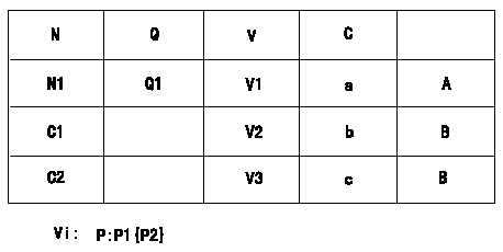
N:Pump speed
Q:Injection quantity
V:Output voltage
C:Position of the control lever
C1:Idle
C2:Full
A:Adjusting point
B:Checking point
P:Boost pressure
Vi:Applied voltage
----------
----------
N1=1000r/min Vi=10.00V Q1=20.8+-1.0cm3/1,000st V1=4.66+-0.03V V2=(1.00)V V3=(7.80)V P1=-kPa P2=-mmHg a=(20.5)deg b=0deg c=43+-3deg
----------
----------
N1=1000r/min Vi=10.00V Q1=20.8+-1.0cm3/1,000st V1=4.66+-0.03V V2=(1.00)V V3=(7.80)V P1=-kPa P2=-mmHg a=(20.5)deg b=0deg c=43+-3deg
0000001901 SIDE LINK LEVER ADJUSTMENT
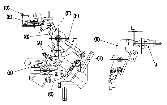
Side link lever adjustment
1. Adjusting the side link lever
Hold the control lever (D) at position a.
With the side link lever (G) contacting the stopper (H), turn the A/T lever (F) lightly clockwise to eliminate any rod (E) play.
At this time, adjust the length of rod (E) so that the gap between the A/T lever (F) and the lever (G) is S. Then fix.
J = idle switch
L = the dimension when the switch is depressed (ie, on)
----------
a=0deg S=1+-0.2mm
----------
S=1+-0.2mm b=10deg
----------
a=0deg S=1+-0.2mm
----------
S=1+-0.2mm b=10deg
0000002001 W-CSD ADJUSTMENT
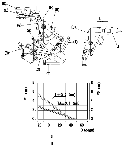
Adjustment of the W-CSD
1. Adjustment of the advance angle of the timer
(1)Determine the timer advance angle using the graph.
(2)Adjust screw A so that the timer advance angle determined in item (1) is obtained.
2. Adjustment of the W-FICD
Adjust the rod (I) so that the clearance from the control lever is L as determined from the graph.
At this time, CSD lever (B) and FICD lever (C) must contact. When the FICD lever is rotated clockwise, confirm that (D), (E), (F), (G), and (H) operate with no play.
Y1 = timer stroke TA
Y2 = control lever gap L
X = temperature t
G = timer stroke TA:
H = control lever gap L:
----------
----------
TA=-0.041t+2.46 (t>=-20degC) L=-0.0925t+3.65 (t>=-20decC)
----------
----------
TA=-0.041t+2.46 (t>=-20degC) L=-0.0925t+3.65 (t>=-20decC)
Information:
Table 4
Cat Specification for Neat (B100) Biodiesel Blending Fuel
Property Test Method, United States Test Method, International Units Limits, B100 Blending Fuel
Density at 15°C “ASTM D1298” “ISO 3675” g/cm3 0.86-0.90
Viscosity at 40°C “ASTM D445” “ISO 3104” mm2/s (cSt) 1.9-6.0
Flash Point “ASTM D93” “ISO 3679” °C 93 minimum
Pour Point - - - 6 °C (10 °F) minimum below ambient temperature
- Summer “ASTM D97” “ISO 3016” °C
- Winter
Cloud Point “ASTM D2500” °C Report
Sulfur Content(1) “ASTM D5453” “ISO 20846” “ISO 20884” percent weight 0.0015(2) maximum
Distillation - - - -
T90 “ASTM D86” “ISO 3924” °C 360
Cetane Number “ASTM D613” “ISO 5165” % evaporation 45 minimum
Sulfated Ash “ASTM D874” “ISO 3987” or "ISO 6245" percent weight 0.02 maximum
Water and Sediment “ASTM D2709” “ISO 12937” percent volume 0.05 maximum
Water "ASTM D1796" "EN ISO 12937" % m/m -
Copper Corrosion, 3 hours at 50oC “ASTM D130” “ISO 2160” - No. 1
Oxidation Stability “EN 14112” or "EN 15751" “EN 14112” or "EN 15751" hours 3 minimum
Ramsbottom Carbon Residue on 10% bottoms "ASTM D524" “ISO 10370” %-m/m 0.30 maximum
Carbon Residue, Conradson (CCR) “ASTM D4530” - percent weight 0.05 maximum
Esterification "ASTM D 7806" or "ASTM D 7371" “EN 14103” percent volume 97.5 minimum
Total Acid Number “ASTM D664” “EN 14104” mg KOH/g 0.5 maximum
Methanol Content “EN 14110” “EN 14110” percent weight 0.2 maximum
Monoglycerides “ASTM D6584” “EN 14105” percent weight 0.8 maximum
Diglycerides “ASTM D6584” “EN 14105” percent weight 0.2 maximum
Triglycerides “ASTM D6584” “EN 14105” percent weight 0.2 maximum
Free Glycerin “ASTM D6584” “EN 14105” percent weight 0.02 maximum
Total Glycerin “ASTM D6584” “EN 14105” percent weight 0.240 maximum
Phosphorus Content “ASTM D4951” “EN 14107” percent weight 0.001 maximum
Calcium plus Magnesium “EN 14538” “EN 14538” ppm 5 maximum
Sodium plus Potassium “EN 14538” “EN 14538” ppm 5 maximum
Cold Soak Filterability “ASTM D7501” – seconds 360 maximum
Cleanliness “ASTM D7619” “ISO 4406” – (3)
Total contamination "EN 12662" "EN 12662" mg/kg 24 maximum
Appearance "ASTM D4176" - - Clear and Bright
(1) Methods for testing S are based on the sulfur content in diesel fuel used for blending. Consult with the fuel supplier and ensure the correct method has been used
(2) Sulfur level must be per local regulations. Higher S levels may be used where allowed.
(3) Recommended cleanliness level for fuel as dispensed into the engine fuel tank is ISO 18/16/13 or cleaner per the test methods listed. Refer to the contamination control Chapter for more details.Note: Fuels that meet the most current revision level of "ASTM D6751" or "EN 14214" may be used for blending with an acceptable distillate fuel. The conditions, recommendations, and limits that are noted in this Biodiesel section apply.Referenced Documents
Refer to the “Reference Material - Fuel” section of this Special Publication for the reference material for the information in this section.