Information injection-pump assembly
ZEXEL
104740-0400
1047400400
MAZDA
PN4113800
pn4113800

Rating:
Cross reference number
ZEXEL
104740-0400
1047400400
MAZDA
PN4113800
pn4113800
Zexel num
Bosch num
Firm num
Name
Calibration Data:
Adjustment conditions
Test oil
1404 Test oil ISO4113orSAEJ967d
1404 Test oil ISO4113orSAEJ967d
Test oil temperature
degC
45
45
50
Nozzle
105780-0060
Bosch type code
NP-DN0SD1510
Nozzle holder
105780-2150
Opening pressure
MPa
13
13
13.3
Opening pressure
kgf/cm2
133
133
136
Injection pipe
157805-7320
Injection pipe
Inside diameter - outside diameter - length (mm) mm 2-6-450
Inside diameter - outside diameter - length (mm) mm 2-6-450
Joint assembly
157641-4720
Tube assembly
157641-4020
Transfer pump pressure
kPa
20
20
20
Transfer pump pressure
kgf/cm2
0.2
0.2
0.2
Direction of rotation (viewed from drive side)
Right R
Right R
Injection timing adjustment
Pump speed
r/min
1500
1500
1500
Average injection quantity
mm3/st.
29.2
28.7
29.7
Difference in delivery
mm3/st.
2.5
Basic
*
Injection timing adjustment_02
Pump speed
r/min
2635
2635
2635
Average injection quantity
mm3/st.
16.8
14.3
19.3
Injection timing adjustment_03
Pump speed
r/min
2350
2350
2350
Average injection quantity
mm3/st.
31.5
29.5
33.5
Injection timing adjustment_04
Pump speed
r/min
1500
1500
1500
Average injection quantity
mm3/st.
29.2
28.2
30.2
Injection timing adjustment_05
Pump speed
r/min
1000
1000
1000
Average injection quantity
mm3/st.
28
26
30
Injection quantity adjustment
Pump speed
r/min
2635
2635
2635
Average injection quantity
mm3/st.
16.8
14.8
18.8
Difference in delivery
mm3/st.
4
Basic
*
Injection quantity adjustment_02
Pump speed
r/min
2850
2850
2850
Average injection quantity
mm3/st.
5
Governor adjustment
Pump speed
r/min
410
410
410
Average injection quantity
mm3/st.
11.3
10.3
12.3
Difference in delivery
mm3/st.
2
Basic
*
Governor adjustment_02
Pump speed
r/min
410
410
410
Average injection quantity
mm3/st.
11.3
10.3
12.3
Governor adjustment_03
Pump speed
r/min
750
750
750
Average injection quantity
mm3/st.
3
Timer adjustment
Pump speed
r/min
100
100
100
Average injection quantity
mm3/st.
65
55
75
Basic
*
Speed control lever angle
Pump speed
r/min
410
410
410
Average injection quantity
mm3/st.
0
0
0
Remarks
Magnet OFF
Magnet OFF
0000000901
Pump speed
r/min
1500
1500
1500
Overflow quantity
cm3/min
450
318
582
Stop lever angle
Pump speed
r/min
1500
1500
1500
Pressure
kPa
637.5
608
667
Pressure
kgf/cm2
6.5
6.2
6.8
Basic
*
Stop lever angle_02
Pump speed
r/min
1500
1500
1500
Pressure
kPa
637.5
608
667
Pressure
kgf/cm2
6.5
6.2
6.8
Stop lever angle_03
Pump speed
r/min
2350
2350
2350
Pressure
kPa
825.5
814
837
Pressure
kgf/cm2
8.6
8.3
8.9
0000001101
Pump speed
r/min
1500
1500
1500
Timer stroke
mm
6.8
6.6
7
Basic
*
_02
Pump speed
r/min
1000
1000
1000
Timer stroke
mm
4.1
3.7
4.5
_03
Pump speed
r/min
1500
1500
1500
Timer stroke
mm
6.8
6.6
7
_04
Pump speed
r/min
2000
2000
2000
Timer stroke
mm
9.6
9.2
10
_05
Pump speed
r/min
2250
2250
2250
Timer stroke
mm
11.05
10.6
11.5
0000001201
Max. applied voltage
V
8
8
8
Test voltage
V
13
12
14
0000001401
Pump speed
r/min
1500
1500
1500
Average injection quantity
mm3/st.
22.5
22
23
Timer stroke variation dT
mm
1.2
1
1.4
Basic
*
_02
Pump speed
r/min
1250
1250
1250
Average injection quantity
mm3/st.
22.5
21.5
23.5
Timer stroke variation dT
mm
1.2
0.9
1.5
_03
Pump speed
r/min
1250
1250
1250
Average injection quantity
mm3/st.
14
12.5
15.5
Timer stroke variation dT
mm
2.4
1.9
2.9
Timing setting
K dimension
mm
3.3
3.2
3.4
KF dimension
mm
5.72
5.62
5.82
MS dimension
mm
1.2
1.1
1.3
Control lever angle alpha
deg.
25
21
29
Control lever angle beta
deg.
43
40
46
Test data Ex:
0000001801 W-CSD ADJUSTMENT
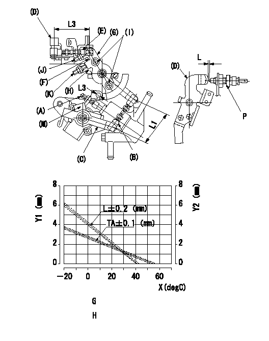
Adjustment of the W-CSD
1. Adjustment of the advance angle of the timer
(1)Determine the timer advance angle using the graph.
(2)Adjust screw A so that the timer advance angle determined in item (1) is obtained.
2. Adjustment of the W-FICD
Adjust the screw (K) so that the control lever clearance is L as determined from the graph, then fix.
At this time, the CSD lever (B)'s length must be 1 mm.
Ensure the CSD lever (O) and the FICD lever (C) are contacting each other and confirm that (D), (E), (B), (G) and (H) operate with no play when the FICD lever is turned clockwise.
Y1 = timer stroke TA
P = idle switch
Y2 = control lever gap L
X = temperature t
G = timer stroke TA:
H = control lever gap L:
----------
L1=53+-0.5mm
----------
TA=-0.049t+2.73 L=-0.0975t+4.15 L1=53+-0.5mm L2=53+-0.5mm a=10+-1deg L3=Dia.6.2mm
----------
L1=53+-0.5mm
----------
TA=-0.049t+2.73 L=-0.0975t+4.15 L1=53+-0.5mm L2=53+-0.5mm a=10+-1deg L3=Dia.6.2mm
0000001901 SIDE LINK LEVER ADJUSTMENT
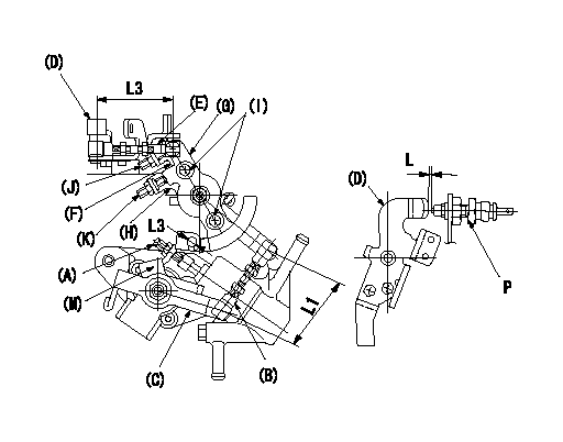
Side link lever adjustment
1. Adjusting the side link lever
Hold the control lever (D) at position a.
Adjust the length of rod (E) to 1 mm and fix.
Adjust screw (J) so that the center of the A/T lever(G)'s hole L2 is b, then fix the screw.
At this time, fix the A/T lever (G) and the lever (F) using bolt (I).
P = idle switch
----------
a=0deg L1=53+-0.5mm L2=Dia.6.2mm b=10+-1deg
----------
L1=53+-0.5mm L2=Dia.6.2mm L3=53+-0.5mm b=10+-1deg
----------
a=0deg L1=53+-0.5mm L2=Dia.6.2mm b=10+-1deg
----------
L1=53+-0.5mm L2=Dia.6.2mm L3=53+-0.5mm b=10+-1deg
Information:
Install the new 291-5165 Bellows (10) to tube assembly (2) by placing the end of the bellows with the liner on the flange of the tube assembly. Secure bellows (10) to tube assembly (2) by using one new 202-1838 V Band Clamp (11). Refer to Illustration 7.
Illustration 8 g01794917
(12) 313-9428 Tube As
Install the flanged end of the new 313-9428 Tube As (12) to bellows (10) by using one new V-band clamp (11). Refer to Illustration 8.Note: Make sure that the tube assembly is temporarily supported so that the tube assembly axis lines up with the axis of the bellows before securing the tube assembly to the bellows. That way the weight of the tube is on the support and not on the bellows.
Illustration 9 g01794933
(13) 294-9631 Clamp As (14) 310-7675 Bracket (15) 5P-1076 Hard Washer (16) 8T-4183 Bolt
Install the bottom half of the new 294-9631 Clamp As (13) to the two new 310-7675 Brackets (14) by using two new 5P-1076