Information injection-pump assembly
ZEXEL
104740-0392
1047400392
MAZDA
PN4013800B
pn4013800b
Rating:
Components :
| 0. | INJECTION-PUMP ASSEMBLY | 104740-0392 |
| 1. | _ | |
| 2. | FUEL INJECTION PUMP | |
| 3. | NUMBER PLATE | 146905-0000 |
| 4. | _ | |
| 5. | CAPSULE | 146620-0120 |
| 6. | ADJUSTING DEVICE | |
| 7. | NOZZLE AND HOLDER ASSY | 105148-1183 |
| 8. | Nozzle and Holder | PN40 13 H50C |
| 9. | Open Pre:MPa(Kqf/cm2) | 10.8{110} |
| 10. | NOZZLE-HOLDER | 105078-0111 |
| 11. | NOZZLE | 105007-1210 |
Scheme ###:
| 1/6. | [1] | 146601-0100 | PACKING RING |
| 6. | [1] | 146100-0120 | SUPPLY PUMP D20 |
| 9. | [1] | 146103-0000 | COVER |
| 10. | [2] | 139104-0000 | FLAT-HEAD SCREW |
| 12/1. | [1] | 146200-0300 | DRIVE SHAFT |
| 12/2. | [1] | 146201-0000 | WOODRUFF KEY |
| 12/3. | [2] | 146202-0100 | DAMPER |
| 12/4. | [1] | 146203-0000 | TOOTHED GEAR |
| 17. | [1] | 146204-0000 | PLAIN WASHER |
| 20. | [1] | 146210-2620 | ROLLER SET |
| 24. | [1] | 146303-0100 | BEARING PIN |
| 25. | [1] | 146304-0000 | BEARING PIN |
| 26. | [1] | 146305-0000 | CLAMPING BAND |
| 27. | [1] | 146205-0000 | SLOTTED WASHER |
| 29. | [1] | 146220-1320 | CAM PLATE '13'4LC5 |
| 30. | [1] | 146600-0800 | O-RING |
| 31. | [1] | 146300-1400 | PUMP PLUNGER ' 14' 7-12. |
| 32. | [1] | 146301-0000 | SLIDING PIECE |
| 33. | [1] | 146603-0700 | SHIM |
| 34. | [1] | 146302-8400 | COMPRESSION SPRING K=2.05 |
| 35/1. | [1] | 146603-0700 | SHIM |
| 35/1. | [1] | 146603-0800 | SHIM |
| 35/1. | [1] | 146603-0900 | SHIM |
| 35/1. | [1] | 146603-1000 | SHIM |
| 35/1. | [1] | 146603-1100 | SHIM |
| 35/1. | [1] | 146603-3600 | SHIM |
| 36. | [1] | 146600-0800 | O-RING |
| 37. | [1] | 146310-0700 | COVER |
| 38. | [2] | 146620-5000 | BLEEDER SCREW |
| 39. | [1] | 146310-0100 | COVER |
| 40. | [2] | 146620-5000 | BLEEDER SCREW |
| 43. | [1] | 146230-0000 | SHIM |
| 44. | [1] | 146230-0100 | PLAIN WASHER |
| 45. | [1] | 146231-0000 | SLOTTED WASHER |
| 47. | [2] | 146233-0000 | SLOTTED WASHER |
| 48/1. | [1] | 146603-0000 | SHIM |
| 48/1. | [1] | 146603-0100 | SHIM |
| 48/1. | [1] | 146603-0200 | SHIM |
| 48/1. | [1] | 146603-0300 | SHIM |
| 48/1. | [1] | 146603-0400 | SHIM |
| 48/1. | [1] | 146603-0500 | SHIM |
| 48/1. | [1] | 146603-0600 | SHIM |
| 48/1. | [1] | 146690-1400 | SHIM |
| 48/1. | [1] | 146690-1500 | SHIM |
| 48/1. | [1] | 146690-1600 | SHIM |
| 48/1. | [1] | 146690-1700 | SHIM |
| 48/1. | [1] | 146690-1800 | SHIM |
| 48/1. | [1] | 146690-1900 | SHIM |
| 49. | [2] | 146234-0120 | GUIDE PIN |
| 50. | [1] | 146403-2820 | HYDRAULIC HEAD D10 2X2.0 A0.2 |
| 50. | [1] | 146403-2820 | HYDRAULIC HEAD D10 2X2.0 A0.2 |
| 50. | [1] | 146403-2820 | HYDRAULIC HEAD D10 2X2.0 A0.2 |
| 51. | [1] | 146600-0000 | O-RING |
| 52/1. | [1] | 146420-0000 | SHIM |
| 52/1. | [1] | 146420-0100 | SHIM |
| 52/1. | [1] | 146420-0200 | SHIM |
| 52/1. | [1] | 146420-0300 | SHIM |
| 52/1. | [1] | 146420-0400 | SHIM |
| 52/1. | [1] | 146420-0500 | SHIM |
| 52/1. | [1] | 146420-0600 | SHIM |
| 52/1. | [1] | 146420-0700 | SHIM |
| 52/1. | [1] | 146420-0800 | SHIM |
| 52/1. | [1] | 146420-0900 | SHIM |
| 52/1. | [1] | 146420-1000 | SHIM |
| 52/1. | [1] | 146420-1100 | SHIM |
| 52/1. | [1] | 146420-1200 | SHIM |
| 52/1. | [1] | 146420-1300 | SHIM |
| 52/1. | [1] | 146420-1400 | SHIM |
| 52/1. | [1] | 146420-1500 | SHIM |
| 52/1. | [1] | 146420-1600 | SHIM |
| 52/1. | [1] | 146420-1700 | SHIM |
| 52/1. | [1] | 146420-1800 | SHIM |
| 52/1. | [1] | 146420-1900 | SHIM |
| 52/1. | [1] | 146420-2000 | SHIM |
| 52/1. | [1] | 146420-2100 | SHIM |
| 52/1. | [1] | 146420-2200 | SHIM |
| 52/1. | [1] | 146420-2300 | SHIM |
| 52/1. | [1] | 146420-2400 | SHIM |
| 52/1. | [1] | 146420-2500 | SHIM |
| 52/1. | [1] | 146420-2600 | SHIM |
| 52/1. | [1] | 146420-2700 | SHIM |
| 52/1. | [1] | 146420-2800 | SHIM |
| 52/1. | [1] | 146420-2900 | SHIM |
| 52/1. | [1] | 146420-3000 | SHIM |
| 52/1. | [1] | 146420-3100 | SHIM |
| 52/1. | [1] | 146420-3200 | SHIM |
| 52/1. | [1] | 146420-3300 | SHIM |
| 52/1. | [1] | 146420-3400 | SHIM |
| 52/1. | [1] | 146420-3500 | SHIM |
| 52/1. | [1] | 146420-3600 | SHIM |
| 52/1. | [1] | 146420-3700 | SHIM |
| 52/1. | [1] | 146420-3800 | SHIM |
| 52/1. | [1] | 146420-3900 | SHIM |
| 52/1. | [1] | 146420-4000 | SHIM |
| 52/1. | [1] | 146420-4100 | SHIM |
| 52/1. | [1] | 146420-4200 | SHIM |
| 52/1. | [1] | 146420-4300 | SHIM |
| 52/1. | [1] | 146420-4400 | SHIM |
| 52/1. | [1] | 146420-4500 | SHIM |
| 52/1. | [1] | 146420-4600 | SHIM |
| 52/1. | [1] | 146420-4700 | SHIM |
| 52/1. | [1] | 146420-4800 | SHIM |
| 52/1. | [1] | 146420-4900 | SHIM |
| 52/1. | [1] | 146420-5000 | SHIM |
| 52/1. | [1] | 146420-5100 | SHIM |
| 52/1. | [1] | 146420-5200 | SHIM |
| 52/1. | [1] | 146420-5300 | SHIM |
| 52/1. | [1] | 146420-5400 | SHIM |
| 52/1. | [1] | 146420-5500 | SHIM |
| 52/1. | [1] | 146420-5600 | SHIM |
| 52/1. | [1] | 146420-5700 | SHIM |
| 52/1. | [1] | 146420-5800 | SHIM |
| 54. | [4] | 146433-0100 | GASKET |
| 55. | [4] | 146430-3420 | DELIVERY-VALVE ASSEMBLY 'VE34'VR30 |
| 56. | [4] | 146432-0000 | COMPRESSION SPRING K=0.48 |
| 58. | [4] | 146440-0220 | FITTING D0.45 L=50 |
| 60. | [3] | 139106-0100 | FLAT-HEAD SCREW |
| 66. | [1] | 146600-0100 | O-RING |
| 67. | [1] | 146503-4720 | GOVERNOR COVER |
| 67/1. | [1] | 146508-4921 | GOVERNOR COVER |
| 67/14. | [1] | 146621-1700 | UNION NUT |
| 67/16. | [1] | 146526-2800 | BLEEDER SCREW |
| 67/23. | [1] | 146927-0800 | BRACKET |
| 67/24. | [2] | 139006-4400 | BLEEDER SCREW |
| 67/78. | [1] | 146600-1000 | SEAL RING |
| 67/200. | [1] | 139308-0300 | PLAIN WASHER |
| 67/201. | [1] | 146545-3400 | THREADED PIN |
| 67/201B. | [1] | 146545-3500 | THREADED PIN |
| 67/201C. | [1] | 146545-3600 | THREADED PIN |
| 67/202. | [1] | 139208-0900 | UNION NUT |
| 67/203. | [1] | 146600-1200 | O-RING |
| 68. | [1] | 146513-8920 | CONTROL SHAFT R=10 S R |
| 69. | [1] | 139310-0200 | PLAIN WASHER |
| 72. | [1] | 146536-7220 | CONTROL LEVER '672' |
| 72B. | [1] | 146536-7320 | CONTROL LEVER '673' |
| 73. | [1] | 014110-6440 | LOCKING WASHER |
| 75. | [1] | 013020-6040 | UNION NUT |
| 95. | [1] | 146851-0220 | FULCRUM LEVER I=2.2 SKH51 |
| 104. | [2] | 146568-0000 | SLOTTED SPRING PIN |
| 105. | [2] | 026508-1140 | GASKET |
| 106. | [2] | 146588-0500 | COILED SPRING |
| 107. | [1] | 146569-0300 | UNION NUT з |
| 108. | [1] | 146570-0420 | GOVERNOR SHAFT R-L/T |
| 109. | [1] | 146600-0400 | O-RING |
| 110/1. | [1] | 146571-0000 | SHIM |
| 110/1. | [1] | 146571-0100 | SHIM |
| 110/1. | [1] | 146571-0200 | SHIM |
| 110/1. | [1] | 146571-0300 | SHIM |
| 110/1. | [1] | 146571-0400 | SHIM |
| 110/1. | [1] | 146571-0500 | SHIM |
| 110/1. | [1] | 146571-0600 | SHIM |
| 110/1. | [1] | 146571-0700 | SHIM |
| 110/1. | [1] | 146571-0800 | SHIM |
| 111. | [1] | 146602-0600 | PLAIN WASHER |
| 112. | [1] | 146572-0020 | FLYWEIGHT ASSEMBLY |
| 114. | [1] | 146602-0500 | PLAIN WASHER |
| 115. | [1] | 146575-3700 | SLIDING SLEEVE '37' D0.5G2-0.3 |
| 116. | [1] | 146576-0200 | CAP |
| 117/1. | [1] | 146577-1800 | PLUG |
| 117/1. | [1] | 146577-1900 | PLUG |
| 117/1. | [1] | 146577-2000 | PLUG |
| 117/1. | [1] | 146577-2100 | PLUG |
| 117/1. | [1] | 146577-2200 | PLUG |
| 117/1. | [1] | 146577-2300 | PLUG |
| 117/1. | [1] | 146577-2400 | PLUG |
| 117/1. | [1] | 146577-2500 | PLUG |
| 117/1. | [1] | 146577-2600 | PLUG |
| 117/1. | [1] | 146577-2700 | PLUG |
| 117/1. | [1] | 146577-2800 | PLUG |
| 117/1. | [1] | 146577-2900 | PLUG |
| 117/1. | [1] | 146577-3000 | PLUG |
| 117/1. | [1] | 146577-3100 | PLUG |
| 117/1. | [1] | 146577-3200 | PLUG |
| 117/1. | [1] | 146577-3300 | PLUG |
| 117/1. | [1] | 146577-6700 | PLUG |
| 117/1. | [1] | 146577-6800 | PLUG |
| 117/1. | [1] | 146577-6900 | PLUG |
| 117/1. | [1] | 146577-7000 | PLUG |
| 117/1. | [1] | 146577-7100 | PLUG |
| 117/1. | [1] | 146577-7200 | PLUG |
| 117/1. | [1] | 146577-7300 | PLUG |
| 117/1. | [1] | 146577-7400 | PLUG |
| 117/1. | [1] | 146577-7500 | PLUG |
| 117/1. | [1] | 146577-7600 | PLUG |
| 117/1. | [1] | 146577-7700 | PLUG |
| 117/1. | [1] | 146577-7800 | PLUG |
| 117/1. | [1] | 146577-7900 | PLUG |
| 117/1. | [1] | 146577-8000 | PLUG |
| 117/1. | [1] | 146577-8100 | PLUG |
| 117/1. | [1] | 146877-0000 | PLUG |
| 117/1. | [1] | 146877-0100 | PLUG |
| 117/1. | [1] | 146877-0200 | PLUG |
| 117/1. | [1] | 146877-0300 | PLUG |
| 123. | [3] | 139106-0200 | FLAT-HEAD SCREW |
| 130. | [1] | 146421-0020 | CAPSULE D14 |
| 130/2. | [1] | 026508-1140 | GASKET |
| 130/3. | [1] | 146422-0000 | BLEEDER SCREW |
| 130/4. | [1] | 146600-0500 | O-RING |
| 133. | [1] | 146600-0600 | O-RING |
| 134. | [1] | 146600-0700 | O-RING |
| 135. | [1] | 146110-0220 | CONTROL VALVE '02'4XD1.6K=1.5 |
| 135/5. | [1] | 146114-0000 | SPRING WASHER |
| 136. | [1] | 146120-1120 | OVER FLOW VALVE |
| 137. | [2] | 026512-1540 | GASKET |
| 138. | [1] | 146608-3220 | INLET UNION OUT B2 |
| 200. | [1] | 146206-0100 | COILED SPRING |
| 205. | [1] | 029470-4030 | WOODRUFF KEY |
| 220. | [1] | 146587-8300 | COILED SPRING |
| 221. | [1] | 146927-5720 | BRACKET |
| 232. | [1] | 146659-3600 | CLAMPING BAND |
| 236. | [1] | 139006-4800 | BLEEDER SCREW |
| 237. | [1] | 146620-0200 | HEX-SOCKET-HEAD CAP SCREW |
| 240. | [1] | 146650-4320 | PULLING ELECTROMAGNET |
| 240/8. | [1] | 146600-1700 | O-RING |
| 242. | [1] | 146662-0820 | WIRE ' ' 12V |
| 243. | [1] | 146621-1000 | UNION NUT |
| 245. | [3] | 026512-1540 | GASKET |
| 246. | [1] | 139812-1900 | EYE BOLT |
| 247. | [1] | 146608-4920 | INLET UNION IN B3 |
| 248. | [1] | 146614-0200 | SPACER BUSHING |
| 252. | [1] | 139006-4400 | BLEEDER SCREW |
| 275. | [1] | 146612-5800 | BRACKET |
| 276. | [2] | 010010-1640 | BLEEDER SCREW |
| 280. | [1] | 146360-8920 | START ADVANCE ASSY PN |
| 281. | [1] | 146600-0800 | O-RING |
| 316. | [1] | 146680-4320 | DAMPER PN |
| 316. | [1] | 146680-4320 | DAMPER PN |
| 480. | [1] | 013020-6040 | UNION NUT |
| 481. | [1] | 146620-2800 | FLAT-HEAD SCREW |
| 800S. | [1] | 146019-8920 | PUMP HOUSING |
| 800S/1/6. | [1] | 146601-0100 | PACKING RING |
| 800S/1/6. | [1] | 146601-0100 | PACKING RING |
| 804S. | [1] | 146232-0720 | COMPRESSION SPRING |
| 805S. | [1] | 146574-0120 | PARTS SET |
| 810S. | [1] | 146600-2420 | REPAIR SET |
| 835S. | [1] | 146598-1000 | CAP LOAD |
| 836S/1. | [1] | 146598-0600 | CAP SPEED L=18 |
| 836S/1. | [1] | 146598-0700 | CAP SPEED L=21 |
| 836S/1. | [1] | 146598-0800 | CAP SPEED L=24 |
| 836S/1. | [1] | 146598-0900 | CAP SPEED L=27 |
| 903. | [1] | 146620-0120 | CAPSULE |
| 903/2. | [1] | 146600-1300 | O-RING |
| 906. | [1] | 146905-0000 | NAMEPLATE PN |
Include in #2:
104740-0392
as INJECTION-PUMP ASSEMBLY
Cross reference number
ZEXEL
104740-0392
1047400392
MAZDA
PN4013800B
pn4013800b
Zexel num
Bosch num
Firm num
Name
Calibration Data:
Adjustment conditions
Test oil
1404 Test oil ISO4113orSAEJ967d
1404 Test oil ISO4113orSAEJ967d
Test oil temperature
degC
45
45
50
Nozzle
105780-0060
Bosch type code
NP-DN0SD1510
Nozzle holder
105780-2150
Opening pressure
MPa
13
13
13.3
Opening pressure
kgf/cm2
133
133
136
Injection pipe
157805-7320
Injection pipe
Inside diameter - outside diameter - length (mm) mm 2-6-450
Inside diameter - outside diameter - length (mm) mm 2-6-450
Joint assembly
157641-4720
Tube assembly
157641-4020
Transfer pump pressure
kPa
20
20
20
Transfer pump pressure
kgf/cm2
0.2
0.2
0.2
Direction of rotation (viewed from drive side)
Right R
Right R
Injection timing adjustment
Pump speed
r/min
1500
1500
1500
Average injection quantity
mm3/st.
31.8
31.3
32.3
Difference in delivery
mm3/st.
2.5
Basic
*
Injection timing adjustment_02
Pump speed
r/min
2635
2635
2635
Average injection quantity
mm3/st.
12.4
9.9
14.9
Injection timing adjustment_03
Pump speed
r/min
2350
2350
2350
Average injection quantity
mm3/st.
30.1
28.1
32.1
Injection timing adjustment_04
Pump speed
r/min
1500
1500
1500
Average injection quantity
mm3/st.
31.8
30.8
32.8
Injection timing adjustment_05
Pump speed
r/min
1000
1000
1000
Average injection quantity
mm3/st.
30.2
28.2
32.2
Injection quantity adjustment
Pump speed
r/min
2635
2635
2635
Average injection quantity
mm3/st.
12.4
10.4
14.4
Difference in delivery
mm3/st.
4
Basic
*
Injection quantity adjustment_02
Pump speed
r/min
2850
2850
2850
Average injection quantity
mm3/st.
5
Governor adjustment
Pump speed
r/min
410
410
410
Average injection quantity
mm3/st.
7
6
8
Difference in delivery
mm3/st.
2
Basic
*
Governor adjustment_02
Pump speed
r/min
410
410
410
Average injection quantity
mm3/st.
7
6
8
Governor adjustment_03
Pump speed
r/min
500
500
500
Average injection quantity
mm3/st.
3
Timer adjustment
Pump speed
r/min
100
100
100
Average injection quantity
mm3/st.
70
60
80
Basic
*
Speed control lever angle
Pump speed
r/min
410
410
410
Average injection quantity
mm3/st.
0
0
0
Remarks
Magnet OFF
Magnet OFF
0000000901
Pump speed
r/min
1500
1500
1500
Overflow quantity
cm3/min
558
408
708
Stop lever angle
Pump speed
r/min
1500
1500
1500
Pressure
kPa
539.5
520
559
Pressure
kgf/cm2
5.5
5.3
5.7
Basic
*
Stop lever angle_02
Pump speed
r/min
1500
1500
1500
Pressure
kPa
539.5
520
559
Pressure
kgf/cm2
5.5
5.3
5.7
Stop lever angle_03
Pump speed
r/min
2350
2350
2350
Pressure
kPa
755.5
726
785
Pressure
kgf/cm2
7.7
7.4
8
0000001101
Pump speed
r/min
1500
1500
1500
Timer stroke
mm
6.2
6
6.4
Basic
*
_02
Pump speed
r/min
1000
1000
1000
Timer stroke
mm
2.5
1.9
3.1
_03
Pump speed
r/min
1500
1500
1500
Timer stroke
mm
6.2
5.9
6.5
_04
Pump speed
r/min
2350
2350
2350
Timer stroke
mm
10.1
9.6
10.6
0000001201
Max. applied voltage
V
8
8
8
Test voltage
V
13
12
14
0000001401
Pump speed
r/min
1500
1500
1500
Average injection quantity
mm3/st.
21.6
21.1
22.1
Timer stroke variation dT
mm
1.2
1
1.4
Basic
*
_02
Pump speed
r/min
1500
1500
1500
Average injection quantity
mm3/st.
21.6
20.6
22.6
Timer stroke variation dT
mm
1.2
0.9
1.5
_03
Pump speed
r/min
1500
1500
1500
Average injection quantity
mm3/st.
10
8.5
11.5
Timer stroke variation dT
mm
2.4
1.9
2.9
Timing setting
K dimension
mm
3.3
3.2
3.4
KF dimension
mm
5.72
5.62
5.82
MS dimension
mm
1.2
1.1
1.3
Control lever angle alpha
deg.
25
21
29
Control lever angle beta
deg.
43
38
48
Test data Ex:
0000001801 DASHPOT ADJUSTMENT
Adjustment of the dash pot
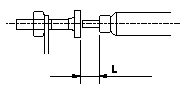
1. With the control lever in the idle position, set the operating screw so that the length of the end of the dashpot is L, then fix using the nut.
----------
L=2.3+-0.3mm
----------
L=2.3+-0.3mm
----------
L=2.3+-0.3mm
----------
L=2.3+-0.3mm
0000001901 W-CSD ADJUSTMENT
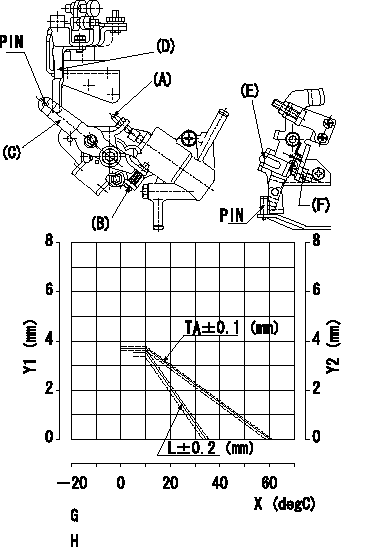
Adjustment of the W-CSD
1. Adjustment of the advance angle of the timer
(1)Determine the timer advance angle using the graph.
(2)Adjust screw A so that the timer advance angle determined in item (1) is obtained.
2. Adjustment of the W-FICD
(1)Insert a block gauge thickness L between the control lever (D)'s adjusting screw (F) and the idle stopper (E).
(2)Adjust using screw B so that the control lever contacts the FICD lever pin and fix using the nut.
Y1 = timer stroke TA
Y2 = control lever gap L
X = temperature t
G = timer stroke TA:
H = control lever gap L:
----------
----------
TA=-0.0738t+4.428 (t>=10degC) L=-0.144t+4.94 (t>=10decC)
----------
----------
TA=-0.0738t+4.428 (t>=10degC) L=-0.144t+4.94 (t>=10decC)
Information:
Illustration 4 g01781374
Illustration 5 g01781397
Relocate the ether canister to the other side. Refer to Illustration 4 and Illustration 5.
Illustration 6 g01781413
(4) 322-7177 Bracket As (15) 8T-4121 Hard Washer (17) 8T-4196 Bolt
Install 322-7177 Bracket As (4) in the same location as the former muffler support bracket (30) by using four 8T-4121 Hard Washers (15), and four 8T-4196 Bolts (17). Refer to Illustration 3 and Illustration 6.
Illustration 7 g01781434
(6) 322-7180 Bracket As (8) 324-1454 Bracket Adapter (10) 5P-4116 Hard Washer (12) 6V-3822 Bolt (15) 8T-4121 Hard Washer (18) 8T-6870 Bolt
Install 322-7180 Bracket As (6) by using two 8T-4121 Hard Washers (15), and two 6V-3822 Bolts (12) to the exhaust elbow mounting holes. Place 324-1454 Bracket Adapter (8) between bracket assembly (6) and the aftercooler core assembly. Secure bracket assembly (6) to bracket adapter (8), and to the aftercooler core assembly by using two 5P-4116 Hard Washers (10), and two 8T-6870 Bolts (18). Refer to Illustration 7.
Illustration 8 g01781454
(5) 322-7179 Plate (15) 8T-4121 Hard Washer (16) 8T-4133 Nut (17) 8T-4196 Bolt
Install 322-7179 Plate (5) on top of bracket assembly (4), and bracket assembly (6). Secure plate (5) loosely using eight 8T-4121 Hard Washers (15), four 8T-4196 Bolts (17), four 8T-4133 Nuts (16). Refer to Illustration 8.
Illustration 9 g01781475
(2) 253-4495 Clamp As
Install two 253-4495 Clamp As (2) on top of plate (5). Use eight hard washers (15), four bolts (17), and four nuts (16). Secure the brackets loosely so that you are able to make adjustments. Refer to Illustration 9.
Illustration 10 g01781478
(c) Inlet tube (7) 322-9842 Diesel Particulate Filter Gp
Install 322-9842 Diesel Particulate Filter Gp (7) on top of the two bottom clamp assemblies (2). Insert inlet tube (c) on top of the exhaust elbow. The weight of the diesel particulate filter group is approximately 60 kg (132 lb). Refer to Illustration 10.
Illustration 11 g01781493
Cut off material from the bracket that originally supported the ether canister (if needed), to fit the diesel particulate filter group. Refer to Illustration 11.
Make sure that the filter is properly placed on top of clamp assemblies (2) and the exhaust elbow. If needed, adjust plate (5), and bracket assemblies (4) and (6). Once diesel particulate filter group (7) is properly positioned, tighten the bolts between the plate and the two bracket assemblies. Also, tighten the bolts of the bottom clamp assemblies (2) .
Illustration 12 g01781513
(d) Outlet tube (1) 7E-3870 Muffler Clamp (3) 277-4718 Clamp As (9) 3B-4508 Lockwasher (11) 5P-8245 Hard Washer (13) 6V-3823 Bolt (14) 6V-8149 Nut
Secure inlet tube (c) of the diesel particulate filter group to the exhaust elbow with one 7E-3870 Muffler Clamp (1). Refer to Illustration 12.
Position one 277-4718 Clamp As (3) over the diesel particulate filter group, and secure the clamp assembly to the bottom clamp assembly (2)