Information injection-pump assembly
ZEXEL
104740-0260
1047400260
MAZDA
SE4213800
se4213800
Rating:
Cross reference number
ZEXEL
104740-0260
1047400260
MAZDA
SE4213800
se4213800
Zexel num
Bosch num
Firm num
Name
Calibration Data:
Adjustment conditions
Test oil
1404 Test oil ISO4113orSAEJ967d
1404 Test oil ISO4113orSAEJ967d
Test oil temperature
degC
45
45
50
Nozzle
105000-2010
Bosch type code
NP-DN12SD12TT
Nozzle holder
105780-2080
Opening pressure
MPa
14.7
14.7
15.19
Opening pressure
kgf/cm2
150
150
155
Injection pipe
Inside diameter - outside diameter - length (mm) mm 2-6-840
Inside diameter - outside diameter - length (mm) mm 2-6-840
Transfer pump pressure
kPa
20
20
20
Transfer pump pressure
kgf/cm2
0.2
0.2
0.2
Direction of rotation (viewed from drive side)
Right R
Right R
Injection timing adjustment
Pump speed
r/min
1000
1000
1000
Average injection quantity
mm3/st.
52.6
52.1
53.1
Difference in delivery
mm3/st.
3.5
Basic
*
Injection timing adjustment_02
Pump speed
r/min
2100
2100
2100
Average injection quantity
mm3/st.
22.1
19.1
25.1
Injection timing adjustment_03
Pump speed
r/min
1900
1900
1900
Average injection quantity
mm3/st.
47.4
45.4
49.4
Injection timing adjustment_04
Pump speed
r/min
1500
1500
1500
Average injection quantity
mm3/st.
51.3
49.3
53.3
Injection timing adjustment_05
Pump speed
r/min
1000
1000
1000
Average injection quantity
mm3/st.
52.6
51.6
53.6
Injection timing adjustment_06
Pump speed
r/min
500
500
500
Average injection quantity
mm3/st.
46.6
44.6
48.6
Injection quantity adjustment
Pump speed
r/min
2100
2100
2100
Average injection quantity
mm3/st.
22.1
19.1
25.1
Basic
*
Injection quantity adjustment_02
Pump speed
r/min
2200
2200
2200
Average injection quantity
mm3/st.
6
Governor adjustment
Pump speed
r/min
350
350
350
Average injection quantity
mm3/st.
12.8
10.8
14.8
Difference in delivery
mm3/st.
2.5
Basic
*
Governor adjustment_02
Pump speed
r/min
350
350
350
Average injection quantity
mm3/st.
12.8
10.8
14.8
Governor adjustment_03
Pump speed
r/min
620
Average injection quantity
mm3/st.
0
0
0
Timer adjustment
Pump speed
r/min
100
100
100
Average injection quantity
mm3/st.
78
78
Basic
*
Speed control lever angle
Pump speed
r/min
350
350
350
Average injection quantity
mm3/st.
0
0
0
Remarks
Magnet OFF
Magnet OFF
0000000901
Pump speed
r/min
1000
1000
1000
Overflow quantity
cm3/min
450
318
582
Stop lever angle
Pump speed
r/min
1500
1500
1500
Pressure
kPa
588.5
559
618
Pressure
kgf/cm2
6
5.7
6.3
Basic
*
Stop lever angle_02
Pump speed
r/min
500
500
500
Pressure
kPa
255
226
284
Pressure
kgf/cm2
2.6
2.3
2.9
Stop lever angle_03
Pump speed
r/min
1500
1500
1500
Pressure
kPa
588.5
559
618
Pressure
kgf/cm2
6
5.7
6.3
Stop lever angle_04
Pump speed
r/min
1900
1900
1900
Pressure
kPa
725.5
696
755
Pressure
kgf/cm2
7.4
7.1
7.7
0000001101
Pump speed
r/min
1500
1500
1500
Timer stroke
mm
5.2
5
5.4
Basic
*
_02
Pump speed
r/min
1000
1000
1000
Timer stroke
mm
2.2
1.6
2.8
_03
Pump speed
r/min
1500
1500
1500
Timer stroke
mm
5.2
4.9
5.5
_04
Pump speed
r/min
1900
1900
1900
Timer stroke
mm
7.6
7
8.2
0000001201
Max. applied voltage
V
8
8
8
Test voltage
V
13
12
14
0000001501
Pump speed
r/min
1000
1000
1000
Atmospheric pressure difference
kPa
-18.7
-18.7
-18.7
Atmospheric pressure difference
mmHg
-140
-140
-140
Average injection quantity
mm3/st.
47.7
46.7
48.7
Basic
*
_02
Pump speed
r/min
1000
1000
1000
Atmospheric pressure difference
kPa
-18.7
-18.7
-18.7
Atmospheric pressure difference
mmHg
-140
-140
-140
Average injection quantity
mm3/st.
47.7
46.2
49.2
Timing setting
K dimension
mm
3.3
3.2
3.4
KF dimension
mm
5.8
5.7
5.9
MS dimension
mm
1.8
1.7
1.9
Pre-stroke
mm
0.2
0.18
0.22
Control lever angle alpha
deg.
20
16
24
Control lever angle beta
deg.
38
33
43
Test data Ex:
0000001501 ANEROID COMPENSATOR
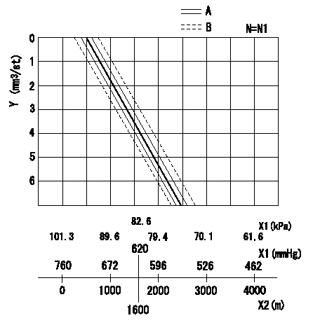
ACS adjustment
Full load injection quantity at high altitudes and ACS adjusting method
1. Full load injection quantity adjustment
(1)Remove the ACS cover and remove the bellows and adjusting shim.
(2)Perform all adjustments as per the adjustment standard except for ACS adjustment.
2. ACS adjustment
(1)Assemble the ACS cover, bellows and adjusting shim.
(2)At N = N1, adjust using shims so that the decrease amount for altitude is as specified in the graph.
N:Pump speed
X1:Atmospheric pressure
X2:Altitude
Y:Decrease quantity
A:Adjustment value
B:Inspection value
----------
N1=1000r/min
----------
----------
N1=1000r/min
----------
Information:
CHECKING FLYWHEEL FACE RUNOUT4. The difference between the lowest and highest readings taken at all four points should not exceed .006 in. (0.15 mm), which is the maximum permissible flywheel face runout.Checking Flywheel Bore Runout
CHECKING FLYWHEEL BORE RUNOUT
1. 7H1945 Holding Rod. 2. 7H1645 Holding Rod. 3. 7H1942 Indicator. 4. 7H1940 Universal Attachment.Make tool setup from parts of the 8S2328 Dial Test Indicator Group.1. Mount the dial indicator and adjust it so the universal attachment contacts the flywheel bore as shown.2. Adjust the dial indicator to read .000 in. (0.0 mm) then take readings every 90° around the flywheel.3. The difference between the lowest and highest readings taken at all four points should not exceed .006 in. (0.15 mm), which is the maximum permissible flywheel bore runout. Flywheel clutch pilot bearing bore runout should not exceed .005 in. (0.13 mm).
CHECKING FLYWHEEL CLUTCH PILOT BEARING BOREElectrical System
Most of the testing of the electrical system can be done on the engine. The wiring insulation must be in good condition, the wire and cable connections clean and tight and the battery fully charged. If on the engine test shows a defect in a component, remove the component for more testing. The wire size, color and recommendations of length are given in the WIRING DIAGRAMS in SYSTEMS OPERATION.Battery
9S1990 Battery Charger Tester.The battery circuit is an electrical load on the charging unit. The load is variable because of the condition of the charge in the battery. Damage to the charging unit will result, if the connections, (either positive or negative) between the battery and charging unit are broken while the charging unit is charging. This is because the battery load is lost and there is an increase in charging voltage.High voltage will damage, not only the charging unit but also the regulator and other electrical components.
9S1990 BATTERY CHARGER TESTER
Never disconnect any charging unit circuit or battery circuit cable from battery when the charging unit is charging.
Load test a battery that does not hold a charge when in use. To do this, put a resistance, across the battery main connections (terminals). For a 6 volt battery, put a resistance of two times the ampere/hour rating of the battery. For a 12 volt battery, put a resistance of three times the ampere/hour rating. Let the resistance remove the charge (discharge the battery) for 15 seconds. Immediately test the battery voltage. A 6 volt battery in good condition will test 4.5 volts; a 12 volt battery in good condition will test 9 volts.The Special Instruction (GEG00058) with the 9S1990 Charger Tester gives the battery testing procedure.Charging System
Battery
The condition of charge in the battery at each regular inspection will show if the charging system is operating correctly. An adjustment is necessary when the battery is always in a low condition of charge or a large amount of water is needed (one ounce per cell per week or every 50 service hours).Test the charging units and voltage regulators on the engine, when possible, using wiring and components that are