Information injection-pump assembly
ZEXEL
104740-0240
1047400240
MAZDA
SE0823500
se0823500
Rating:
Cross reference number
ZEXEL
104740-0240
1047400240
MAZDA
SE0823500
se0823500
Zexel num
Bosch num
Firm num
Name
Calibration Data:
Adjustment conditions
Test oil
1404 Test oil ISO4113orSAEJ967d
1404 Test oil ISO4113orSAEJ967d
Test oil temperature
degC
45
45
50
Nozzle
105000-2010
Bosch type code
NP-DN12SD12TT
Nozzle holder
105780-2080
Opening pressure
MPa
14.7
14.7
15.19
Opening pressure
kgf/cm2
150
150
155
Injection pipe
Inside diameter - outside diameter - length (mm) mm 2-6-840
Inside diameter - outside diameter - length (mm) mm 2-6-840
Transfer pump pressure
kPa
20
20
20
Transfer pump pressure
kgf/cm2
0.2
0.2
0.2
Direction of rotation (viewed from drive side)
Right R
Right R
Injection timing adjustment
Pump speed
r/min
1000
1000
1000
Average injection quantity
mm3/st.
53.6
53.1
54.1
Difference in delivery
mm3/st.
3.5
Basic
*
Injection timing adjustment_02
Pump speed
r/min
2100
2100
2100
Average injection quantity
mm3/st.
22.1
19.1
25.1
Injection timing adjustment_03
Pump speed
r/min
1900
1900
1900
Average injection quantity
mm3/st.
48.4
46.4
50.4
Injection timing adjustment_04
Pump speed
r/min
1500
1500
1500
Average injection quantity
mm3/st.
52.3
50.3
54.3
Injection timing adjustment_05
Pump speed
r/min
1000
1000
1000
Average injection quantity
mm3/st.
53.6
52.6
54.6
Injection timing adjustment_06
Pump speed
r/min
500
500
500
Average injection quantity
mm3/st.
47.6
45.6
49.6
Injection quantity adjustment
Pump speed
r/min
2100
2100
2100
Average injection quantity
mm3/st.
22.1
19.1
25.1
Basic
*
Injection quantity adjustment_02
Pump speed
r/min
2200
2200
2200
Average injection quantity
mm3/st.
6
Governor adjustment
Pump speed
r/min
350
350
350
Average injection quantity
mm3/st.
12.8
10.8
14.8
Difference in delivery
mm3/st.
2.5
Basic
*
Governor adjustment_02
Pump speed
r/min
350
350
350
Average injection quantity
mm3/st.
12.8
10.8
14.8
Governor adjustment_03
Pump speed
r/min
620
Average injection quantity
mm3/st.
0
0
0
Timer adjustment
Pump speed
r/min
100
100
100
Average injection quantity
mm3/st.
78
78
Basic
*
Speed control lever angle
Pump speed
r/min
350
350
350
Average injection quantity
mm3/st.
0
0
0
Remarks
Magnet OFF
Magnet OFF
0000000901
Pump speed
r/min
1000
1000
1000
Overflow quantity
cm3/min
450
318
582
Stop lever angle
Pump speed
r/min
1500
1500
1500
Pressure
kPa
588.5
559
618
Pressure
kgf/cm2
6
5.7
6.3
Basic
*
Stop lever angle_02
Pump speed
r/min
500
500
500
Pressure
kPa
255
226
284
Pressure
kgf/cm2
2.6
2.3
2.9
Stop lever angle_03
Pump speed
r/min
1500
1500
1500
Pressure
kPa
588.5
559
618
Pressure
kgf/cm2
6
5.7
6.3
Stop lever angle_04
Pump speed
r/min
1900
1900
1900
Pressure
kPa
725.5
696
755
Pressure
kgf/cm2
7.4
7.1
7.7
0000001101
Pump speed
r/min
1500
1500
1500
Timer stroke
mm
5.2
5
5.4
Basic
*
_02
Pump speed
r/min
1000
1000
1000
Timer stroke
mm
2.2
1.6
2.8
_03
Pump speed
r/min
1500
1500
1500
Timer stroke
mm
5.2
4.9
5.5
_04
Pump speed
r/min
1900
1900
1900
Timer stroke
mm
7.6
7
8.2
0000001201
Max. applied voltage
V
16
16
16
Test voltage
V
25
24
26
Timing setting
K dimension
mm
3.3
3.2
3.4
KF dimension
mm
5.8
5.7
5.9
MS dimension
mm
1.8
1.7
1.9
Pre-stroke
mm
0.2
0.18
0.22
Control lever angle alpha
deg.
20
16
24
Control lever angle beta
deg.
38
33
43
Test data Ex:
0000001801 M-CSD ADJUSTMENT
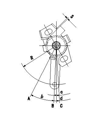
M-CSD adjustment
1. Fixing the M-CSD lever stopper
(1)At roller holder advance angle a adjust the lever shaft ball pin so that it contacts the roller holder.
(2)At this time, fix the stopper in the position where the distance between the M-CSD lever and the stopper is S.
A = at maximum advance (TA = L1 advance)
B = normal position (start of advance)
C = normal position (lever play)
----------
L1=0.5+2mm a=0deg
----------
S=0.5+2mm L1=1.9mm R=50mm b=About 17deg c=(5)deg d=2"30'+-6deg
----------
L1=0.5+2mm a=0deg
----------
S=0.5+2mm L1=1.9mm R=50mm b=About 17deg c=(5)deg d=2"30'+-6deg
Information:
PROBLEM
The existing fuel injectors can experience injector failures due to injector body cracking. If the existing injector fails it can result in complaints of high oil levels due to excessive fuel dilution.
AFFECTED PRODUCT
Model Identification Number
C27 A6X00101-00105
EGG00100
NAR00100-00119
T4Z00100, 200-227, 236
C32 NST00100-00108
SDK00101-00198
PMC27 N1B00100-00105, 107-118, 120-126, 128
PARTS NEEDED
Qty
Part Number Description
2 1R1808 FILTER-LUBE
12 8S9191 BOLT
12 3594060 INJECTOR GP-FUEL
1 BULK_OIL DEO (Refer to the OMM for Refill Capacities)
In order to allow equitable parts availability to all participating dealers, please limit your initial parts order to not exceed 2% of dealership population. This is an initial order recommendation only, and the ultimate responsibility for ordering the total number of parts needed to satisfy the program lies with the dealer.
ACTION REQUIRED
If excessive fuel dilution of engine oil is found reference the following to determine the cause of fuel dilution.
Refer to Special Instruction, REHS3007, "Determining the Cause of Fuel Dilution of Engine Oil"
Troubleshooting C27 and C32 Engines:
UENR0505 C27 Petroleum Generator Set Engines
UENR0504 C27 and C32 Industrial Engines
KENR9192 C27 Generator Set Engines
Once an injector(s) has been identified as having a cracked/leaking injector body, replace the failed injector(s). Inspect the remaining good injector serial numbers with Cat ET, (Injector Serial Numbers = Injector trim file name, (ie 6Cxxxxxxxxxx.trm)). If the remaining injector serial numbers fall within the serial number range below, replace at the same time. Refer to Image 1 for the serial number location on the top of the electronic unit injector.
Injector Serial Numbers
6C001793971D through 6C002198297C
8S-9191 Injector Hold Down Bolt must be replaced.
Refer to Disassembly and Assembly, KENR8167 for the removal, installation, and tightening procedures.
After the engine is reassembled, change the engine oil and filters.
Image1
SERVICE CLAIM ALLOWANCES
Product smu/age whichever comes first Caterpillar Dealer Suggested Customer Suggested
Parts % Labor Hrs% Parts % Labor Hrs% Parts % Labor Hrs%
0-3500 hrs,
0-24 mo 100.0% 100.0% 0.0% 0.0% 0.0% 0.0%
3501-6000 hrs,
25-48 mo 50.0% 50.0% 0.0% 0.0% 50.0% 50.0%
This is a 10.0-hour job
If there has been a previous repair, part age/hours will apply. Retain a copy of the previous repair invoice in the dealer's records for audit purposes, and specify repair date and machine hours in the "Additional Comments" section of the warranty claim.
PARTS DISPOSITION
Handle the parts in accordance with your Warranty Bulletin on warranty parts handling.