Information injection-pump assembly
BOSCH
9 460 614 819
9460614819
ZEXEL
104701-3030
1047013030
Rating:
Cross reference number
BOSCH
9 460 614 819
9460614819
ZEXEL
104701-3030
1047013030
Zexel num
Bosch num
Firm num
Name
Calibration Data:
Adjustment conditions
Test oil
1404 Test oil ISO4113orSAEJ967d
1404 Test oil ISO4113orSAEJ967d
Test oil temperature
degC
45
45
50
Nozzle
105780-0060
Bosch type code
NP-DN0SD1510
Nozzle holder
105780-2150
Opening pressure
MPa
13
13
13.3
Opening pressure
kgf/cm2
133
133
136
Injection pipe
157805-7320
Injection pipe
Inside diameter - outside diameter - length (mm) mm 2-6-450
Inside diameter - outside diameter - length (mm) mm 2-6-450
Joint assembly
157641-4720
Tube assembly
157641-4020
Transfer pump pressure
kPa
20
20
20
Transfer pump pressure
kgf/cm2
0.2
0.2
0.2
Direction of rotation (viewed from drive side)
Right R
Right R
Manual controller assembly
105782-8280
Manual controller
105782-8270
Wire harness
407980-2390
Intermediate harness
407980-2400
Governor adjustment
Pump speed
r/min
1000
1000
1000
TCV duty (%) F TCV 60Hz
%
100
100
100
U alpha soll
V
2.81
2.81
2.81
Pump chamber pressure
kPa
588.5
559
618
Pump chamber pressure
kgf/cm2
6
5.7
6.3
Basic
*
Governor adjustment_02
Pump speed
r/min
100
100
100
TCV duty (%) F TCV 60Hz
%
100
100
100
U alpha soll
V
2.81
2.81
2.81
Pump chamber pressure
kPa
294
294
Pump chamber pressure
kgf/cm2
3
3
Governor adjustment_03
Pump speed
r/min
1000
1000
1000
TCV duty (%) F TCV 60Hz
%
100
100
100
U alpha soll
V
2.81
2.81
2.81
Pump chamber pressure
kPa
588
549
627
Pump chamber pressure
kgf/cm2
6
5.6
6.4
Governor adjustment_04
Pump speed
r/min
2000
2000
2000
TCV duty (%) F TCV 60Hz
%
100
100
100
U alpha soll
V
2.81
2.81
2.81
Pump chamber pressure
kPa
726
677
775
Pump chamber pressure
kgf/cm2
7.4
6.9
7.9
Boost compensator adjustment
Pump speed
r/min
1000
1000
1000
TCV duty (%) F TCV 60Hz
%
100
100
100
U alpha soll
V
2.81
2.81
2.81
Timer stroke
mm
8.6
8.4
8.8
Basic
*
Boost compensator adjustment_02
Pump speed
r/min
100
100
100
TCV duty (%) F TCV 60Hz
%
100
100
100
U alpha soll
V
2.81
2.81
2.81
Timer stroke
mm
3
0.9
5.1
Boost compensator adjustment_03
Pump speed
r/min
350
350
350
TCV duty (%) F TCV 60Hz
%
100
100
100
U alpha soll
V
2.81
2.81
2.81
Timer stroke
mm
6.3
4.2
8.4
Boost compensator adjustment_04
Pump speed
r/min
1000
1000
1000
TCV duty (%) F TCV 60Hz
%
100
100
100
U alpha soll
V
2.81
2.81
2.81
Timer stroke
mm
8.6
8.3
8.9
Boost compensator adjustment_05
Pump speed
r/min
1000
1000
1000
TCV duty (%) F TCV 60Hz
%
80
80
80
U alpha soll
V
2.81
2.81
2.81
Timer stroke
mm
3.6
2
5.2
Boost compensator adjustment_06
Pump speed
r/min
1800
1800
1800
TCV duty (%) F TCV 60Hz
%
100
100
100
U alpha soll
V
2.81
2.81
2.81
Timer stroke
mm
9.75
9.3
10.2
Boost compensator adjustment_07
Pump speed
r/min
2300
2300
2300
TCV duty (%) F TCV 60Hz
%
0
0
0
U alpha soll
V
2.81
2.81
2.81
Timer stroke
mm
0
0
0
Timer adjustment
Pump speed
r/min
1000
1000
1000
TCV duty (%) F TCV 60Hz
%
0
0
0
U alpha soll
V
2.81
2.81
2.81
Vtps
V
0.77
0.45
1.09
Basic
*
Timer adjustment_02
Pump speed
r/min
1000
1000
1000
TCV duty (%) F TCV 60Hz
%
0
0
0
U alpha soll
V
2.81
2.81
2.81
Vtps
V
0.77
0.45
1.09
Timer adjustment_03
Pump speed
r/min
1000
1000
1000
TCV duty (%) F TCV 60Hz
%
100
100
100
U alpha soll
V
2.81
2.81
2.81
Vtps
V
3.704
3.3
4.108
Speed control lever angle
Pump speed
r/min
1000
1000
1000
TCV duty (%) F TCV 60Hz
%
100
100
100
U alpha soll
V
2.81
2.81
2.81
Overflow quantity
cm3/min
560
430
690
0000000901
Pump speed
r/min
1000
1000
1000
U alpha soll + dU alpha soll
V
2.81
2.81
2.81
TCV duty (%) F TCV 60Hz
%
100
100
100
Average injection quantity
mm3/st.
83.8
83.3
84.3
Basic
*
_02
Pump speed
r/min
375
375
375
U alpha soll + dU alpha soll
V
2.17
2.17
2.17
TCV duty (%) F TCV 60Hz
%
100
100
100
Average injection quantity
mm3/st.
20.2
16.7
23.7
Difference in delivery
mm3/st.
2.5
Basic
*
Remarks
Confirmation of difference in delivery
Confirmation of difference in delivery
_03
Pump speed
r/min
800
800
800
U alpha soll + dU alpha soll
V
2.82
2.82
2.82
TCV duty (%) F TCV 60Hz
%
100
100
100
Average injection quantity
mm3/st.
87.6
84.6
90.6
Difference in delivery
mm3/st.
6
Basic
*
Remarks
Confirmation of difference in delivery
Confirmation of difference in delivery
_04
Pump speed
r/min
100
100
100
U alpha soll + dU alpha soll
V
3.16
3.16
3.16
TCV duty (%) F TCV 60Hz
%
100
100
100
Average injection quantity
mm3/st.
75
65
85
_05
Pump speed
r/min
100
100
100
U alpha soll + dU alpha soll
V
2.71
2.71
2.71
TCV duty (%) F TCV 60Hz
%
100
100
100
Average injection quantity
mm3/st.
38.5
28.5
48.5
_06
Pump speed
r/min
200
200
200
U alpha soll + dU alpha soll
V
2.71
2.71
2.71
TCV duty (%) F TCV 60Hz
%
100
100
100
Average injection quantity
mm3/st.
45.8
39.8
51.8
_07
Pump speed
r/min
375
375
375
U alpha soll + dU alpha soll
V
2.17
2.17
2.17
TCV duty (%) F TCV 60Hz
%
100
100
100
Average injection quantity
mm3/st.
20.2
16.7
23.7
_08
Pump speed
r/min
400
400
400
U alpha soll + dU alpha soll
V
2.66
2.66
2.66
TCV duty (%) F TCV 60Hz
%
100
100
100
Average injection quantity
mm3/st.
56
53
59
_09
Pump speed
r/min
500
500
500
U alpha soll + dU alpha soll
V
2.67
2.67
2.67
TCV duty (%) F TCV 60Hz
%
100
100
100
Average injection quantity
mm3/st.
64.9
61.9
67.9
_10
Pump speed
r/min
750
750
750
U alpha soll + dU alpha soll
V
2.6
2.6
2.6
TCV duty (%) F TCV 60Hz
%
100
100
100
Average injection quantity
mm3/st.
67.9
64.9
70.9
_11
Pump speed
r/min
800
800
800
U alpha soll + dU alpha soll
V
2.82
2.82
2.82
TCV duty (%) F TCV 60Hz
%
100
100
100
Average injection quantity
mm3/st.
87.6
84.6
90.6
_12
Pump speed
r/min
1000
1000
1000
U alpha soll + dU alpha soll
V
2.81
2.81
2.81
TCV duty (%) F TCV 60Hz
%
100
100
100
Average injection quantity
mm3/st.
83.8
82.8
84.8
_13
Pump speed
r/min
1500
1500
1500
U alpha soll + dU alpha soll
V
2.87
2.87
2.87
TCV duty (%) F TCV 60Hz
%
100
100
100
Average injection quantity
mm3/st.
89.3
86.3
92.3
_14
Pump speed
r/min
1800
1800
1800
U alpha soll + dU alpha soll
V
2.76
2.76
2.76
TCV duty (%) F TCV 60Hz
%
100
100
100
Average injection quantity
mm3/st.
80.5
77.5
83.5
_15
Pump speed
r/min
2000
2000
2000
U alpha soll + dU alpha soll
V
2.72
2.72
2.72
TCV duty (%) F TCV 60Hz
%
100
100
100
Average injection quantity
mm3/st.
76.1
73.1
79.1
_16
Pump speed
r/min
2475
2475
2475
U alpha soll + dU alpha soll
V
1.72
1.72
1.72
TCV duty (%) F TCV 60Hz
%
100
100
100
Average injection quantity
mm3/st.
25
22
28
Stop lever angle
Pump speed
r/min
2000
2000
2000
U alpha soll + dU alpha soll
V
2.72
2.72
2.72
TCV duty (%) F TCV 60Hz
%
100
100
100
Average injection quantity
cm3/min
0
0
0
0000001101
Pump speed
r/min
200
200
200
TCV duty (%) F TCV 60Hz
%
100
100
100
U alpha soll
V
2.81
2.81
2.81
Speed output
N=Measure the actual speed. r/min N+-8
N=Measure the actual speed. r/min N+-8
0000001201
Pump speed
r/min
1000
1000
1000
TCV duty (%) F TCV 60Hz
%
100
100
100
U alpha soll
V
2.81
2.81
2.81
Temperature output
Measure T = actual output temperature degC T+-5
Measure T = actual output temperature degC T+-5
0000001301
Max. applied voltage
V
8
8
8
Test voltage
V
13
12
14
0000001401
K dimension
mm
3.3
3.2
3.4
KF dimension
mm
5.62
5.52
5.72
Pre-stroke
mm
0.1
0.08
0.12
Test data Ex:
Injection timing adjustment Comp. resistor/voltage
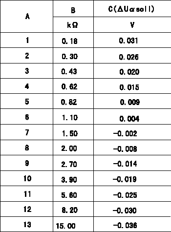
Compensation resistance/compensation voltage comparison
A = Compensation resistor number
B= Compensation resistance
C = Compensation voltage delta U alpha soll
----------
----------
----------
----------
0000001601 HARNESS & CONNECTOR
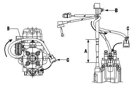
TCV connector assembly specification
(1)Ensure the GE cable is not twisted at section A.
(2)Refer to the figure for the direction of connector clip B.
(3)Route the TCV harness in the direction indicated by the arrows in the figure and install the connector C.
----------
----------
----------
----------
0000001701 HARNESS & CONNECTOR
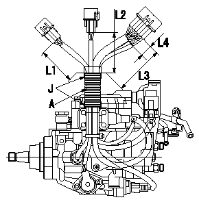
Corrugated tube assembly specification
(1)Position the connector as shown in the figure, and maintain the dimensions shown in the figure for the end of the connector and the end of the corrugated tube.
(2)Wrap black vinyl tape 4 times around the end of the corrugated tube to fix the tube.
A:Corrugated tube
J:PVC tape
L4:Dimension from protective tube to end face of connector
----------
----------
L1=90+-10mm L2=80+-10mm L3=110+-10mm L4=(20mm)
----------
----------
L1=90+-10mm L2=80+-10mm L3=110+-10mm L4=(20mm)
0000001801 HARNESS & CONNECTOR
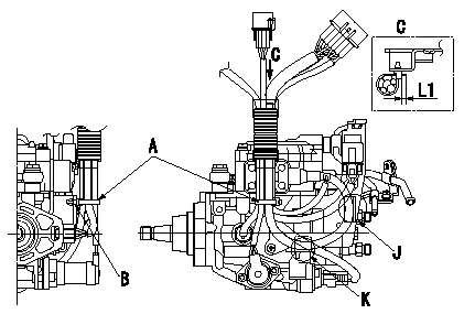
Clip assembly standards (harness fixing)
(1)Fix all the harnesses (GE cable, TCV, FCV, TPS, P/U, Q adjustment) using the clip.
(2)Where the clip holds the harnesses, when fixing the clip to the bracket hole, fix where the GE cable contacts the bracket at J and K.
(3)Be careful of the clip assembly direction because it is fixed to the bracket hole.
(4)After clipping, cut off excess clip leaving L1.
A:Binder
B:Fix at bracket hole.
C:Figure shown by arrow
----------
----------
L1=(2mm)
----------
----------
L1=(2mm)
0000001901 HARNESS & CONNECTOR
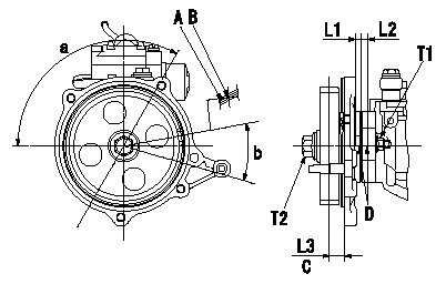
Timing gear assembly standard
A:Paint mark for distinguishing position (above gear tooth with groove)
B:Ideal center of grooved tooth for standard tooth position.
C:Gear tooth's standard position
D:Timing mark stamping
----------
----------
L1=4mm L2=7.5mm L3=16.3mm T1=10~15N-m(1~1.5kgf-m) T2=59~69N-m(6~7kgf-m) a=(120deg) b=(27deg)
----------
----------
L1=4mm L2=7.5mm L3=16.3mm T1=10~15N-m(1~1.5kgf-m) T2=59~69N-m(6~7kgf-m) a=(120deg) b=(27deg)
Information:
The electrical system is a combination of two separate electric circuits: The charging circuit and the starting circuit. Each circuit is dependent on some of the same components. The battery (batteries), on-off start switch, circuit breaker, ammeter, cables and wires from the battery are common in each of the circuits.
The ignition switch must be ON to allow the electrical system to function. Some charging circuit components will be damaged if the engine is operated with the ignition switch OFF.
The charging circuit is in operation when the diesel engine is operating. The electricity producing (charging) unit is an alternator. A regulator in the circuit senses the state of charge in the battery and regulates the alternator output to keep the batter fully charged.The alternator has four main components: end frame assembly (brush end), rotor assembly, stator and shell assembly, and end frame assembly (drive end).A separate regulator senses the charge condition of the battery as well as electrical system power demand and controls the alternator output accordingly by limiting the field current.
ALTERNATOR
Never operate the alternator without the battery in the circuit. Making or breaking an alternator connection with a heavy load on the circuit will sometimes result in regulator damage.
The starting motor is a device used to rotate the flywheel of an engine fast enough to start the engine.
ALTERNATOR REGULATOR
ELECTRIC STARTING MOTORThe starting motor includes a solenoid. The solenoid engages the pinion with the ring gear on the engine flywheel, when the solenoid is energized. The pinion always engages before the electric contacts in the solenoid causes the circuit between the battery and the starting motor to close. An overrunning clutch protects the starting motor from being overspeeded. Releasing the start-switch disengages the pinion and flywheel ring gear.A solenoid is a magnetic switch that uses low current to close a high current circuit. The solenoid is an electro-magnet with a movable core. There are contacts on the end of the core. The contacts are held apart by a spring pushing the core away from the magnetic center of the coil. Low current energizes the coil and forms a magnetic field. The magnetic field pulls the core to the center of the coil, closing the contacts and completing the starting circuit.
SOLENOID