Information injection-pump assembly
BOSCH
9 460 611 509
9460611509
ZEXEL
104701-2042
1047012042
Rating:
Components :
| 0. | INJECTION-PUMP ASSEMBLY | 104701-2042 |
| 1. | _ | |
| 2. | FUEL INJECTION PUMP | 104601-2042 |
| 3. | NUMBER PLATE | 148633-3600 |
| 4. | _ | |
| 5. | CAPSULE | |
| 6. | ADJUSTING DEVICE | 105148-8003 |
| 7. | NOZZLE AND HOLDER ASSY | 105141-2971 |
| 8. | Nozzle and Holder | 16600-1C310 |
| 9. | Open Pre:MPa(Kqf/cm2) | 12.7{130} |
| 10. | NOZZLE-HOLDER | 105071-1361 |
| 11. | NOZZLE | 105000-2210 |
Scheme ###:
| 1/6. | [1] | 146601-0900 | PACKING RING |
| 6. | [1] | 146100-0020 | SUPPLY PUMP |
| 9. | [1] | 148103-0300 | COVER |
| 10. | [2] | 139104-0000 | FLAT-HEAD SCREW |
| 12. | [1] | 148200-0620 | DRIVE SHAFT |
| 12/3. | [1] | 146201-0000 | WOODRUFF KEY |
| 17. | [1] | 146204-0000 | PLAIN WASHER |
| 20. | [1] | 148210-0220 | ROLLER SET |
| 24. | [1] | 146303-0000 | BEARING PIN |
| 25. | [1] | 146304-0000 | BEARING PIN |
| 26. | [1] | 146305-0000 | CLAMPING BAND |
| 27. | [1] | 146205-0000 | SLOTTED WASHER |
| 29. | [1] | 146220-4520 | CAM PLATE |
| 30. | [1] | 146600-0800 | O-RING |
| 31. | [1] | 146300-1900 | PUMP PLUNGER |
| 32. | [1] | 146301-0000 | SLIDING PIECE |
| 33. | [1] | 146603-0700 | SHIM D17.5&7.5T0.60 |
| 34. | [1] | 146306-2100 | COMPRESSION SPRING |
| 35/1. | [0] | 146603-0700 | SHIM D17.5&7.5T0.60 |
| 35/1. | [0] | 146603-0800 | SHIM D17.5&7.5T0.70 |
| 35/1. | [0] | 146603-0900 | SHIM D17.5&7.5T0.90 |
| 35/1. | [0] | 146603-1000 | SHIM D17.5&7.5T1.00 |
| 35/1. | [0] | 146603-1100 | SHIM D17.5&7.5T1.20 |
| 35/1. | [0] | 146603-3600 | SHIM D17.5&7.5T2.40 |
| 36. | [1] | 146600-0800 | O-RING |
| 37. | [1] | 146310-0700 | COVER |
| 38. | [2] | 146620-5000 | BLEEDER SCREW |
| 39. | [1] | 146310-0100 | COVER |
| 40. | [2] | 146620-5000 | BLEEDER SCREW |
| 43. | [1] | 146230-0000 | SHIM |
| 44. | [1] | 146230-0100 | PLAIN WASHER |
| 45. | [1] | 146231-0001 | SLOTTED WASHER |
| 47. | [2] | 146233-0000 | SLOTTED WASHER |
| 48/1. | [1] | 146603-0000 | SHIM D17.0&5.2T0.50 |
| 48/1. | [1] | 146603-0100 | SHIM D17.0&5.2T0.80 |
| 48/1. | [1] | 146603-0200 | SHIM D17.0&5.2T1.00 |
| 48/1. | [1] | 146603-0300 | SHIM D17.0&5.2T1.20 |
| 48/1. | [1] | 146603-0400 | SHIM D17.0&5.2T1.50 |
| 48/1. | [1] | 146603-0500 | SHIM D17.0&5.2T1.80 |
| 48/1. | [1] | 146603-0600 | SHIM D17.0&5.2T2.00 |
| 48/1. | [1] | 146690-1400 | SHIM D17&5.2T0.9 |
| 48/1. | [1] | 146690-1500 | SHIM D17&5.2T1.1 |
| 48/1. | [1] | 146690-1600 | SHIM D17&5.2T1.3 |
| 48/1. | [1] | 146690-1700 | SHIM D17&5.2T1.4 |
| 48/1. | [1] | 146690-1800 | SHIM D17&5.2T1.6 |
| 48/1. | [1] | 146690-1900 | SHIM D17&5.2T1.7 |
| 48/1. | [1] | 146690-5800 | SHIM |
| 48/1. | [1] | 146690-5900 | SHIM |
| 48/1. | [1] | 146690-6000 | SHIM |
| 48/1. | [1] | 146690-6100 | SHIM |
| 48/1. | [1] | 146690-6200 | SHIM |
| 48/1. | [1] | 146690-6300 | SHIM |
| 48/1. | [1] | 146690-6400 | SHIM |
| 48/1. | [1] | 146690-6500 | SHIM |
| 48/1. | [1] | 146690-6600 | SHIM |
| 48/1. | [1] | 146690-6700 | SHIM |
| 48/1. | [1] | 146690-6800 | SHIM |
| 48/1. | [1] | 146690-6900 | SHIM |
| 48/1. | [1] | 146690-7000 | SHIM |
| 48/1. | [1] | 146690-7100 | SHIM |
| 48/1. | [1] | 146690-7200 | SHIM |
| 48/1. | [1] | 146690-7300 | SHIM |
| 48/1. | [1] | 146690-7400 | SHIM |
| 48/1. | [1] | 146690-7500 | SHIM |
| 48/1. | [1] | 146690-7800 | SHIM |
| 49. | [2] | 146234-0600 | GUIDE PIN |
| 50. | [1] | 146403-6120 | HYDRAULIC HEAD |
| 50. | [1] | 146403-6120 | HYDRAULIC HEAD |
| 50. | [1] | 146403-6120 | HYDRAULIC HEAD |
| 51. | [1] | 146600-0000 | O-RING |
| 52/1. | [1] | 146420-0000 | SHIM D9.5&3.0T1.90 |
| 52/1. | [1] | 146420-0100 | SHIM D9.5&3.0T1.92 |
| 52/1. | [1] | 146420-0200 | SHIM D9.5&3.0T1.94 |
| 52/1. | [1] | 146420-0300 | SHIM D9.5&3.0T1.96 |
| 52/1. | [1] | 146420-0400 | SHIM D9.5&3.0T1.98 |
| 52/1. | [1] | 146420-0500 | SHIM D9.5&3.0T2.00 |
| 52/1. | [1] | 146420-0600 | SHIM D9.5&3.0T2.02 |
| 52/1. | [1] | 146420-0700 | SHIM D9.5&3.0T2.04 |
| 52/1. | [1] | 146420-0800 | SHIM D9.5&3.0T2.06 |
| 52/1. | [1] | 146420-0900 | SHIM D9.5&3.0T2.08 |
| 52/1. | [1] | 146420-1000 | SHIM D9.5&3.0T2.10 |
| 52/1. | [1] | 146420-1100 | SHIM D9.5&3.0T2.12 |
| 52/1. | [1] | 146420-1200 | SHIM D9.5&3.0T2.14 |
| 52/1. | [1] | 146420-1300 | SHIM D9.5&3.0T2.16 |
| 52/1. | [1] | 146420-1400 | SHIM D9.5&3.0T2.18 |
| 52/1. | [1] | 146420-1500 | SHIM D9.5&3.0T2.20 |
| 52/1. | [1] | 146420-1600 | SHIM D9.5&3.0T2.22 |
| 52/1. | [1] | 146420-1700 | SHIM D9.5&3.0T2.24 |
| 52/1. | [1] | 146420-1800 | SHIM D9.5&3.0T2.26 |
| 52/1. | [1] | 146420-1900 | SHIM D9.5&3.0T2.28 |
| 52/1. | [1] | 146420-2000 | SHIM D9.5&3.0T2.30 |
| 52/1. | [1] | 146420-2100 | SHIM D9.5&3.0T2.32 |
| 52/1. | [1] | 146420-2200 | SHIM D9.5&3.0T2.34 |
| 52/1. | [1] | 146420-2300 | SHIM D9.5&3.0T2.36 |
| 52/1. | [1] | 146420-2400 | SHIM D9.5&3.0T2.38 |
| 52/1. | [1] | 146420-2500 | SHIM D9.5&3.0T2.40 |
| 52/1. | [1] | 146420-2600 | SHIM D9.5&3.0T2.42 |
| 52/1. | [1] | 146420-2700 | SHIM D9.5&3.0T2.44 |
| 52/1. | [1] | 146420-2800 | SHIM D9.5&3.0T2.46 |
| 52/1. | [1] | 146420-2900 | SHIM D9.5&3.0T2.48 |
| 52/1. | [1] | 146420-3000 | SHIM D9.5&3.0T2.50 |
| 52/1. | [1] | 146420-3100 | SHIM D9.5&3.0T2.52 |
| 52/1. | [1] | 146420-3200 | SHIM D9.5&3.0T2.54 |
| 52/1. | [1] | 146420-3300 | SHIM D9.5&3.0T2.56 |
| 52/1. | [1] | 146420-3400 | SHIM D9.5&3.0T2.58 |
| 52/1. | [1] | 146420-3500 | SHIM D9.5&3.0T2.60 |
| 52/1. | [1] | 146420-3600 | SHIM D9.5&3.0T2.62 |
| 52/1. | [1] | 146420-3700 | SHIM D9.5&3.0T2.64 |
| 52/1. | [1] | 146420-3800 | SHIM D9.5&3.0T2.66 |
| 52/1. | [1] | 146420-3900 | SHIM D9.5&3.0T2.68 |
| 52/1. | [1] | 146420-4000 | SHIM D9.5&3.0T2.70 |
| 52/1. | [1] | 146420-4100 | SHIM D9.5&3.0T2.72 |
| 52/1. | [1] | 146420-4200 | SHIM D9.5&3.0T2.74 |
| 52/1. | [1] | 146420-4300 | SHIM D9.5&3.0T2.76 |
| 52/1. | [1] | 146420-4400 | SHIM D9.5&3.0T2.78 |
| 52/1. | [1] | 146420-4500 | SHIM D9.5&3.0T2.80 |
| 52/1. | [1] | 146420-4600 | SHIM D9.5&3.0T2.82 |
| 52/1. | [1] | 146420-4700 | SHIM D9.5&3.0T2.84 |
| 52/1. | [1] | 146420-4800 | SHIM D9.5&3.0T2.86 |
| 52/1. | [1] | 146420-4900 | SHIM D9.5&3.0T2.88 |
| 52/1. | [1] | 146420-5000 | SHIM D9.5&3.0T2.90 |
| 52/1. | [1] | 146420-5100 | SHIM D9.5&3.0T1.74 |
| 52/1. | [1] | 146420-5200 | SHIM D9.5&3.0T1.76 |
| 52/1. | [1] | 146420-5300 | SHIM D9.5&3.0T1.78 |
| 52/1. | [1] | 146420-5400 | SHIM D9.5&3.0T1.80 |
| 52/1. | [1] | 146420-5500 | SHIM D9.5&3.0T1.82 |
| 52/1. | [1] | 146420-5600 | SHIM D9.5&3.0T1.84 |
| 52/1. | [1] | 146420-5700 | SHIM D9.5&3.0T1.86 |
| 52/1. | [1] | 146420-5800 | SHIM D9.5&3.0T1.88 |
| 54. | [4] | 146433-0100 | GASKET D12&6.4T1.00 |
| 55. | [4] | 146430-5920 | DELIVERY-VALVE ASSEMBLY |
| 56. | [4] | 146432-0700 | COMPRESSION SPRING |
| 58. | [4] | 146440-2720 | FITTING |
| 60. | [3] | 139106-0100 | FLAT-HEAD SCREW |
| 123. | [1] | 146620-8800 | FLAT-HEAD SCREW |
| 130. | [1] | 146421-1020 | CAPSULE |
| 130/2. | [1] | 139508-0200 | GASKET D11.4&8.2T1 |
| 130/3. | [1] | 146422-0300 | BLEEDER SCREW |
| 130/4. | [1] | 146600-0500 | O-RING |
| 133. | [1] | 146600-0600 | O-RING |
| 134. | [1] | 146600-0700 | O-RING |
| 135. | [1] | 146110-3220 | CONTROL VALVE |
| 135/5. | [1] | 146114-0000 | SPRING WASHER |
| 136. | [1] | 148120-0020 | OVER FLOW VALVE |
| 137. | [3] | 139512-0200 | GASKET D18.5&12.2T1.00 |
| 138. | [1] | 146668-5720 | INLET UNION |
| 158. | [1] | 146614-6900 | SPACER BUSHING |
| 200. | [1] | 146206-0100 | COILED SPRING |
| 230. | [1] | 148613-2600 | BRACKET |
| 232. | [1] | 146659-8700 | CLAMPING BAND |
| 236. | [1] | 146620-2700 | HEX-SOCKET-HEAD CAP SCREW |
| 237. | [1] | 146620-0200 | HEX-SOCKET-HEAD CAP SCREW |
| 240. | [1] | 146688-0120 | PULLING ELECTROMAGNET |
| 240/8. | [1] | 146600-1700 | O-RING |
| 243. | [1] | 146621-1000 | UNION NUT |
| 244. | [1] | 020145-1040 | BLEEDER SCREW |
| 245. | [3] | 139512-0200 | GASKET D18.5&12.2T1.00 |
| 246. | [1] | 139812-0500 | EYE BOLT |
| 247. | [1] | 146669-0820 | INLET UNION |
| 248. | [1] | 146614-0200 | SPACER BUSHING |
| 282. | [1] | 139006-4400 | BLEEDER SCREW |
| 298. | [1] | 146659-8800 | CLAMPING BAND |
| 504/1. | [1] | 146649-4500 | RESISTER |
| 504/1. | [1] | 146649-4600 | RESISTER |
| 504/1. | [1] | 146649-4700 | RESISTER |
| 504/1. | [1] | 146649-4800 | RESISTER |
| 504/1. | [1] | 146649-4900 | RESISTER |
| 504/1. | [1] | 146649-5000 | RESISTER |
| 504/1. | [1] | 146649-5100 | RESISTER |
| 504/1. | [1] | 146649-5200 | RESISTER |
| 504/1. | [1] | 146649-5300 | RESISTER |
| 504/1. | [1] | 146649-5400 | RESISTER |
| 504/1. | [1] | 146649-5500 | RESISTER |
| 504/1. | [1] | 146649-5600 | RESISTER |
| 504/1. | [1] | 146649-5700 | RESISTER |
| 505. | [1] | 148531-2420 | GOVERNOR;ELECTRIC |
| 506. | [3] | 146620-8900 | FLAT-HEAD SCREW |
| 514. | [1] | 146659-8600 | CLAMPING BAND |
| 515. | [1] | 106144-1061 | TIMING CONTROL VALVE |
| 515/8. | [1] | 161440-3800 | O-RING |
| 515/9. | [1] | 161440-3700 | O-RING |
| 516. | [2] | 010206-1440 | HEX-SOCKET-HEAD CAP SCREW M6P1L14 |
| 531. | [1] | 479765-2221 | PULSE GENERATOR |
| 531/6. | [1] | 479773-6500 | O-RING |
| 800S. | [1] | 148009-0320 | PUMP HOUSING |
| 800S/1/6. | [1] | 146601-0900 | PACKING RING |
| 804S. | [1] | 146232-0720 | COMPRESSION SPRING |
| 810S. | [1] | 146600-4620 | REPAIR SET |
| 821S. | [1] | 146210-5720 | ROLLER SET |
| 878S. | [1] | 148600-1300 | SEAL RING |
| 906. | [1] | 148633-3600 | NAMEPLATE |
Include in #2:
104701-2042
as INJECTION-PUMP ASSEMBLY
Cross reference number
BOSCH
9 460 611 509
9460611509
ZEXEL
104701-2042
1047012042
Zexel num
Bosch num
Firm num
Name
Calibration Data:
Adjustment conditions
Test oil
1404 Test oil ISO4113orSAEJ967d
1404 Test oil ISO4113orSAEJ967d
Test oil temperature
degC
45
45
50
Nozzle
105780-0060
Bosch type code
NP-DN0SD1510
Nozzle holder
105780-2150
Opening pressure
MPa
13
13
13.3
Opening pressure
kgf/cm2
133
133
136
Injection pipe
157805-7320
Injection pipe
Inside diameter - outside diameter - length (mm) mm 2-6-450
Inside diameter - outside diameter - length (mm) mm 2-6-450
Joint assembly
157641-4720
Tube assembly
157641-4020
Transfer pump pressure
kPa
20
20
20
Transfer pump pressure
kgf/cm2
0.2
0.2
0.2
Direction of rotation (viewed from drive side)
Right R
Right R
Governor adjustment
Pump speed
r/min
1000
1000
1000
TCV duty (%) F TCV 60Hz
%
100
100
100
U alpha soll
V
2.7
2.7
2.7
Pump chamber pressure
kPa
617.5
588
647
Pump chamber pressure
kgf/cm2
6.3
6
6.6
Basic
*
Governor adjustment_02
Pump speed
r/min
100
100
100
TCV duty (%) F TCV 60Hz
%
100
100
100
U alpha soll
V
2.7
2.7
2.7
Pump chamber pressure
kPa
294
294
Pump chamber pressure
kgf/cm2
3
3
Governor adjustment_03
Pump speed
r/min
1000
1000
1000
TCV duty (%) F TCV 60Hz
%
100
100
100
U alpha soll
V
2.7
2.7
2.7
Pump chamber pressure
kPa
618
579
657
Pump chamber pressure
kgf/cm2
6.3
5.9
6.7
Governor adjustment_04
Pump speed
r/min
2000
2000
2000
TCV duty (%) F TCV 60Hz
%
100
100
100
U alpha soll
V
2.7
2.7
2.7
Pump chamber pressure
kPa
755
706
804
Pump chamber pressure
kgf/cm2
7.7
7.2
8.2
Boost compensator adjustment
Pump speed
r/min
1000
1000
1000
TCV duty (%) F TCV 60Hz
%
70
70
70
U alpha soll
V
2.7
2.7
2.7
Timer stroke
mm
4.1
3.9
4.3
Basic
*
Boost compensator adjustment_02
Pump speed
r/min
500
500
500
TCV duty (%) F TCV 60Hz
%
100
100
100
U alpha soll
V
2.7
2.7
2.7
Timer stroke
mm
7.4
5.4
9.4
Boost compensator adjustment_03
Pump speed
r/min
1000
1000
1000
TCV duty (%) F TCV 60Hz
%
100
100
100
U alpha soll
V
2.7
2.7
2.7
Timer stroke
mm
8.1
6.1
10.1
Boost compensator adjustment_04
Pump speed
r/min
1000
1000
1000
TCV duty (%) F TCV 60Hz
%
70
70
70
U alpha soll
V
2.7
2.7
2.7
Timer stroke
mm
4.1
3.8
4.4
Boost compensator adjustment_05
Pump speed
r/min
1000
1000
1000
TCV duty (%) F TCV 60Hz
%
0
0
0
U alpha soll
V
2.7
2.7
2.7
Timer stroke
mm
0
0
0
Boost compensator adjustment_06
Pump speed
r/min
1500
1500
1500
TCV duty (%) F TCV 60Hz
%
100
100
100
U alpha soll
V
2.7
2.7
2.7
Timer stroke
mm
9.75
9.3
10.2
Speed control lever angle
Pump speed
r/min
1000
1000
1000
TCV duty (%) F TCV 60Hz
%
100
100
100
U alpha soll
V
2.7
2.7
2.7
Overflow quantity
cm3/min
600
470
730
0000000901
Pump speed
r/min
1000
1000
1000
U alpha soll + dU alpha soll
V
2.8
2.8
2.8
TCV duty (%) F TCV 60Hz
%
100
100
100
Average injection quantity
mm3/st.
80.5
80
81
Difference in delivery
mm3/st.
5
Basic
*
_02
Pump speed
r/min
375
375
375
U alpha soll + dU alpha soll
V
1.89
1.89
1.89
TCV duty (%) F TCV 60Hz
%
100
100
100
Average injection quantity
mm3/st.
7
4
10
Difference in delivery
mm3/st.
2
Basic
*
Remarks
Confirmation of difference in delivery
Confirmation of difference in delivery
_03
Pump speed
r/min
2500
2500
2500
U alpha soll + dU alpha soll
V
1.66
1.66
1.66
TCV duty (%) F TCV 60Hz
%
100
100
100
Average injection quantity
mm3/st.
16.1
13.6
18.6
Difference in delivery
mm3/st.
5
Basic
*
Remarks
Confirmation of difference in delivery
Confirmation of difference in delivery
_04
Pump speed
r/min
100
100
100
U alpha soll + dU alpha soll
V
3.5
3.5
3.5
TCV duty (%) F TCV 60Hz
%
100
100
100
Average injection quantity
mm3/st.
83.3
73.3
93.3
_05
Pump speed
r/min
375
375
375
U alpha soll + dU alpha soll
V
1.89
1.89
1.89
TCV duty (%) F TCV 60Hz
%
100
100
100
Average injection quantity
mm3/st.
7
4
10
_06
Pump speed
r/min
500
500
500
U alpha soll + dU alpha soll
V
2.49
2.49
2.49
TCV duty (%) F TCV 60Hz
%
100
100
100
Average injection quantity
mm3/st.
50.1
48.1
52.1
_07
Pump speed
r/min
800
800
800
U alpha soll + dU alpha soll
V
1.86
1.86
1.86
TCV duty (%) F TCV 60Hz
%
100
100
100
Average injection quantity
mm3/st.
15.4
13.4
17.4
_08
Pump speed
r/min
800
800
800
U alpha soll + dU alpha soll
V
2.62
2.62
2.62
TCV duty (%) F TCV 60Hz
%
100
100
100
Average injection quantity
mm3/st.
64.4
62.4
66.4
_09
Pump speed
r/min
1000
1000
1000
U alpha soll + dU alpha soll
V
1.85
1.85
1.85
TCV duty (%) F TCV 60Hz
%
100
100
100
Average injection quantity
mm3/st.
16.6
14.6
18.6
_10
Pump speed
r/min
1000
1000
1000
U alpha soll + dU alpha soll
V
2.8
2.8
2.8
TCV duty (%) F TCV 60Hz
%
100
100
100
Average injection quantity
mm3/st.
80.5
79.5
81.5
_11
Pump speed
r/min
2000
2000
2000
U alpha soll + dU alpha soll
V
2.58
2.58
2.58
TCV duty (%) F TCV 60Hz
%
100
100
100
Average injection quantity
mm3/st.
63.7
61.7
65.7
_12
Pump speed
r/min
2250
2250
2250
U alpha soll + dU alpha soll
V
2.43
2.43
2.43
TCV duty (%) F TCV 60Hz
%
100
100
100
Average injection quantity
mm3/st.
54.3
51.8
56.8
_13
Pump speed
r/min
2500
2500
2500
U alpha soll + dU alpha soll
V
1.66
1.66
1.66
TCV duty (%) F TCV 60Hz
%
100
100
100
Average injection quantity
mm3/st.
16.1
13.6
18.6
_14
Pump speed
r/min
2500
2500
2500
U alpha soll + dU alpha soll
V
1
1
1
TCV duty (%) F TCV 60Hz
%
100
100
100
Average injection quantity
mm3/st.
3
Stop lever angle
Pump speed
r/min
375
375
375
U alpha soll + dU alpha soll
V
1.89
1.89
1.89
TCV duty (%) F TCV 60Hz
%
0
0
0
Average injection quantity
cm3/min
0
0
0
Stop lever angle_02
Pump speed
r/min
2250
2250
2250
U alpha soll + dU alpha soll
V
2.43
2.43
2.43
TCV duty (%) F TCV 60Hz
%
100
100
100
Average injection quantity
cm3/min
0
0
0
0000001101
Pump speed
r/min
200
200
200
TCV duty (%) F TCV 60Hz
%
100
100
100
U alpha soll
V
2.7
2.7
2.7
Speed output
N=Measure the actual speed. r/min N+-8
N=Measure the actual speed. r/min N+-8
0000001201
Pump speed
r/min
1000
1000
1000
TCV duty (%) F TCV 60Hz
%
100
100
100
U alpha soll
V
2.8
2.8
2.8
Temperature output
Measure T = actual output temperature degC T+-5
Measure T = actual output temperature degC T+-5
0000001301
Max. applied voltage
V
8
8
8
Test voltage
V
13
12
14
0000001401
K dimension
mm
3.3
3.2
3.4
KF dimension
mm
5.62
5.52
5.72
Pre-stroke
mm
0.1
0.08
0.12
Test data Ex:
Injection timing adjustment Comp. resistor/voltage
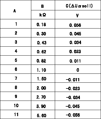
Compensation resistance/compensation voltage comparison
A = Compensation resistor number
B= Compensation resistance
C = Compensation voltage delta U alpha soll
----------
----------
----------
----------
0000001601 HARNESS & CONNECTOR
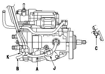
Pickup, TCV harness fixing standards
(1)Fix the pickup harness using the clip at J and K. At this time, fix it so that there is not excessive slack between J and K.
(2)The TCV harness must be clipped at K. Because it is clipped together with the pickup harness, be careful of the harness layout.
(3)Bend the clips over when fixing at J and K to ensure that they are fixed securely.
(4)After bending the clip at J, push the clip towards the pump so that the harness does not move up.
A:Pickup harness
B:T.C.V. harness
C:Clips (J, K)
----------
----------
----------
----------
0000001701 HARNESS & CONNECTOR
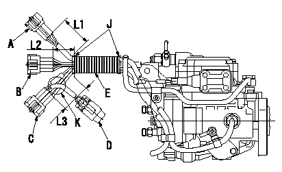
Corrugated tube assembly specification
(1)Maintain the corrugated tube so that the dimension of the end of the connector and the end of the corrugated are as shown in the figure.
(2)At K, pull the Q adjustment resistor forward towards the clip.
(3)Wrap black vinyl tape 4 times around the end of the corrugated tube to fix the tube.
A:RS03M-GY
B:RS08M-GY
C:RS08M-B
D:Q adjustment resistor
E:Corrugated tube
J:PVC tape
----------
----------
L1=80+-10mm L2=50+-10mm L3=60+-10mm
----------
----------
L1=80+-10mm L2=50+-10mm L3=60+-10mm
0000001801 HARNESS & CONNECTOR
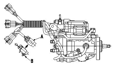
Q adjustment resistor clip assembly specifications
(1)After fixing the corrugated tube, install clip B to the Q adjustment resistor.
A:Injection quantity adjustment compensation resistor (Q adjustment resistor)
B:Clip (be careful of installation direction)
----------
----------
----------
----------
0000001901 HARNESS & CONNECTOR
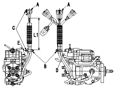
Harness position specification
(1)Fix all of the harnesses so that they are L1 from the face of A's connector.
(2)Be careful of the clip and connector clip positions.
(3)Fix the clip holding the harness to the bracket hole.
A:RS08M-GY Connector
B:Binder
C:clip
D:Bracket hole
E:Fix at bracket hole.
----------
----------
L1=161+-5mm
----------
----------
L1=161+-5mm
0000002001 HARNESS & CONNECTOR
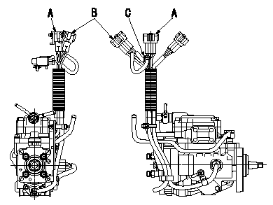
Q adjustment connector (harness) temporary fixing specifications
(1)After clipping the harness, etc and completing all procedures, insert the Q adjustment connector (harness) between A and B and fix it temporarily.
A:RS08M-GY Connector
B:RS08M-B Connector
C:Q adjustment connector (harness)
----------
----------
----------
----------
Information:
To receive satisfactory engine performance with maximum fuel economy and service life, the following engine operation instructions must be applied. In addition, it is necessary to also apply the recommendations of the vehicle manufacturer as well as the every day rules of good driving.After the engine starts, reduce engine RPM to low idle with no load. When normal oil pressure is reached, operate the engine at low load for 5 minutes before applying full load.Stop Engine At Once If Any Part Fails
Almost all failures give a warning to the operator before the part completely fails. If the operator is alert and heeds the warnings, further damage may not happen. A few of the warning signs are: abnormal gauge readings, abnormal fluid levels, fluid leaks, unusual engine noises and excessive smoke. Do not operate an engine if any sign of part failure is present, only a few seconds can ruin an entire engine.Start vehicle in motion by utilizing the lowest gear speed in the transmission that will enable the engine to easily start the load without slipping the clutch. Accelerate smoothly and evenly until the engine speed reaches approximately 100% of rated RPM. Rapid depression of accelerator will result in undesirable heavy exhaust smoke and high fuel consumption with no increase in vehicle performance. Upshift to the next higher gear speed. If properly done, the engine speed will be above approximately 80% of rated RPM when the load is applied. For best performance do not skip gears. Engine speed should not be permitted to drop appreciably below 80% of rated RPM, to avoid a lugging condition.Caterpillar engines have good lugging characteristics; however, operating in a lug condition for extended periods of time should be avoided as it causes exhaust temperatures to rise and also results in high fuel consumption. A lug condition exists when an increase in engine speed cannot be achieved with an increase in accelerator pedal position, or when engine speed decreases with the accelerator pedal in its maximum position. A lug condition can exist at any engine speed below full load speed. Continue to make successive upshifts through each gear speed in the transmission until cruising speed is reached. In each gear speed, accelerate smoothly to an engine speed of approximately 100% of rated RPM before upshifting to the next gear. For highway cruising, maintain the engine speed between approximately 80% and 100% of rated RPM. Operating in this range will give maximum fuel economy.When going up a grade and the engine speed drops to below approximately 80% of rated RPM, downshift successively until a gear speed is reached that will enable the engine to pull the load without operating in a lug condition. When pulling a long grade, such as encountered in mountain driving, make additional downshifts of one or two gears immediately prior to reaching the summit. This will allow the engine to cool more slowly than if the load on the engine is suddenly changed from a full load condition going uphill to
Almost all failures give a warning to the operator before the part completely fails. If the operator is alert and heeds the warnings, further damage may not happen. A few of the warning signs are: abnormal gauge readings, abnormal fluid levels, fluid leaks, unusual engine noises and excessive smoke. Do not operate an engine if any sign of part failure is present, only a few seconds can ruin an entire engine.Start vehicle in motion by utilizing the lowest gear speed in the transmission that will enable the engine to easily start the load without slipping the clutch. Accelerate smoothly and evenly until the engine speed reaches approximately 100% of rated RPM. Rapid depression of accelerator will result in undesirable heavy exhaust smoke and high fuel consumption with no increase in vehicle performance. Upshift to the next higher gear speed. If properly done, the engine speed will be above approximately 80% of rated RPM when the load is applied. For best performance do not skip gears. Engine speed should not be permitted to drop appreciably below 80% of rated RPM, to avoid a lugging condition.Caterpillar engines have good lugging characteristics; however, operating in a lug condition for extended periods of time should be avoided as it causes exhaust temperatures to rise and also results in high fuel consumption. A lug condition exists when an increase in engine speed cannot be achieved with an increase in accelerator pedal position, or when engine speed decreases with the accelerator pedal in its maximum position. A lug condition can exist at any engine speed below full load speed. Continue to make successive upshifts through each gear speed in the transmission until cruising speed is reached. In each gear speed, accelerate smoothly to an engine speed of approximately 100% of rated RPM before upshifting to the next gear. For highway cruising, maintain the engine speed between approximately 80% and 100% of rated RPM. Operating in this range will give maximum fuel economy.When going up a grade and the engine speed drops to below approximately 80% of rated RPM, downshift successively until a gear speed is reached that will enable the engine to pull the load without operating in a lug condition. When pulling a long grade, such as encountered in mountain driving, make additional downshifts of one or two gears immediately prior to reaching the summit. This will allow the engine to cool more slowly than if the load on the engine is suddenly changed from a full load condition going uphill to
