Information injection-pump assembly
BOSCH
9 460 611 108
9460611108
ZEXEL
104701-2021
1047012021
NISSAN
167007F400
167007f400

Rating:
Components :
| 0. | INJECTION-PUMP ASSEMBLY | 104701-2021 |
| 1. | _ | |
| 2. | FUEL INJECTION PUMP | 104601-2021 |
| 3. | NUMBER PLATE | 148633-1700 |
| 4. | _ | |
| 5. | CAPSULE | |
| 6. | ADJUSTING DEVICE | |
| 7. | NOZZLE AND HOLDER ASSY | 105148-1221 |
| 8. | Nozzle and Holder | 16600-63G01 |
| 9. | Open Pre:MPa(Kqf/cm2) | 9.8{100} |
| 10. | NOZZLE-HOLDER | 105078-0050 |
| 11. | NOZZLE | 105007-1210 |
Scheme ###:
| 1/6. | [1] | 146601-0900 | PACKING RING |
| 6. | [1] | 146100-0020 | SUPPLY PUMP |
| 9. | [1] | 148103-0300 | COVER |
| 10. | [2] | 139104-0000 | FLAT-HEAD SCREW |
| 12. | [1] | 148200-0620 | DRIVE SHAFT |
| 12/3. | [1] | 146201-0000 | WOODRUFF KEY |
| 17. | [1] | 146204-0000 | PLAIN WASHER |
| 20. | [1] | 148210-0220 | ROLLER SET |
| 24. | [1] | 146303-0000 | BEARING PIN |
| 25. | [1] | 146304-0000 | BEARING PIN |
| 26. | [1] | 146305-0000 | CLAMPING BAND |
| 27. | [1] | 146205-0000 | SLOTTED WASHER |
| 29. | [1] | 146220-4520 | CAM PLATE |
| 30. | [1] | 146600-3000 | O-RING |
| 31. | [1] | 146300-1900 | PUMP PLUNGER |
| 32. | [1] | 146301-0200 | SLIDING PIECE |
| 33. | [1] | 146603-0700 | SHIM D17.5&7.5T0.60 |
| 34. | [1] | 146306-2100 | COMPRESSION SPRING |
| 35/1. | [0] | 146603-0700 | SHIM D17.5&7.5T0.60 |
| 35/1. | [0] | 146603-0800 | SHIM D17.5&7.5T0.70 |
| 35/1. | [0] | 146603-0900 | SHIM D17.5&7.5T0.90 |
| 35/1. | [0] | 146603-1000 | SHIM D17.5&7.5T1.00 |
| 35/1. | [0] | 146603-1100 | SHIM D17.5&7.5T1.20 |
| 35/1. | [0] | 146603-3600 | SHIM D17.5&7.5T2.40 |
| 36. | [1] | 146600-3000 | O-RING |
| 37. | [1] | 146310-0700 | COVER |
| 38. | [2] | 146620-5000 | BLEEDER SCREW |
| 39. | [1] | 146310-0100 | COVER |
| 40. | [2] | 146620-5000 | BLEEDER SCREW |
| 43. | [1] | 146230-0000 | SHIM |
| 44. | [1] | 146230-0100 | PLAIN WASHER |
| 45. | [1] | 146231-0001 | SLOTTED WASHER |
| 47. | [2] | 146233-0000 | SLOTTED WASHER |
| 48/1. | [1] | 146603-0000 | SHIM D17.0&5.2T0.50 |
| 48/1. | [1] | 146603-0100 | SHIM D17.0&5.2T0.80 |
| 48/1. | [1] | 146603-0200 | SHIM D17.0&5.2T1.00 |
| 48/1. | [1] | 146603-0300 | SHIM D17.0&5.2T1.20 |
| 48/1. | [1] | 146603-0400 | SHIM D17.0&5.2T1.50 |
| 48/1. | [1] | 146603-0500 | SHIM D17.0&5.2T1.80 |
| 48/1. | [1] | 146603-0600 | SHIM D17.0&5.2T2.00 |
| 48/1. | [1] | 146690-1400 | SHIM D17&5.2T0.9 |
| 48/1. | [1] | 146690-1500 | SHIM D17&5.2T1.1 |
| 48/1. | [1] | 146690-1600 | SHIM D17&5.2T1.3 |
| 48/1. | [1] | 146690-1700 | SHIM D17&5.2T1.4 |
| 48/1. | [1] | 146690-1800 | SHIM D17&5.2T1.6 |
| 48/1. | [1] | 146690-1900 | SHIM D17&5.2T1.7 |
| 48/1. | [1] | 146690-5800 | SHIM |
| 48/1. | [1] | 146690-5900 | SHIM |
| 48/1. | [1] | 146690-6000 | SHIM |
| 48/1. | [1] | 146690-6100 | SHIM |
| 48/1. | [1] | 146690-6200 | SHIM |
| 48/1. | [1] | 146690-6300 | SHIM |
| 48/1. | [1] | 146690-6400 | SHIM |
| 48/1. | [1] | 146690-6500 | SHIM |
| 48/1. | [1] | 146690-6600 | SHIM |
| 48/1. | [1] | 146690-6700 | SHIM |
| 48/1. | [1] | 146690-6800 | SHIM |
| 48/1. | [1] | 146690-6900 | SHIM |
| 48/1. | [1] | 146690-7000 | SHIM |
| 48/1. | [1] | 146690-7100 | SHIM |
| 48/1. | [1] | 146690-7200 | SHIM |
| 48/1. | [1] | 146690-7300 | SHIM |
| 48/1. | [1] | 146690-7400 | SHIM |
| 48/1. | [1] | 146690-7500 | SHIM |
| 48/1. | [1] | 146690-7800 | SHIM |
| 49. | [2] | 146234-0120 | GUIDE PIN |
| 50. | [1] | 146403-6120 | HYDRAULIC HEAD |
| 50. | [1] | 146403-6120 | HYDRAULIC HEAD |
| 50. | [1] | 146403-6120 | HYDRAULIC HEAD |
| 51. | [1] | 146600-0000 | O-RING |
| 52/1. | [1] | 146420-0000 | SHIM D9.5&3.0T1.90 |
| 52/1. | [1] | 146420-0100 | SHIM D9.5&3.0T1.92 |
| 52/1. | [1] | 146420-0200 | SHIM D9.5&3.0T1.94 |
| 52/1. | [1] | 146420-0300 | SHIM D9.5&3.0T1.96 |
| 52/1. | [1] | 146420-0400 | SHIM D9.5&3.0T1.98 |
| 52/1. | [1] | 146420-0500 | SHIM D9.5&3.0T2.00 |
| 52/1. | [1] | 146420-0600 | SHIM D9.5&3.0T2.02 |
| 52/1. | [1] | 146420-0700 | SHIM D9.5&3.0T2.04 |
| 52/1. | [1] | 146420-0800 | SHIM D9.5&3.0T2.06 |
| 52/1. | [1] | 146420-0900 | SHIM D9.5&3.0T2.08 |
| 52/1. | [1] | 146420-1000 | SHIM D9.5&3.0T2.10 |
| 52/1. | [1] | 146420-1100 | SHIM D9.5&3.0T2.12 |
| 52/1. | [1] | 146420-1200 | SHIM D9.5&3.0T2.14 |
| 52/1. | [1] | 146420-1300 | SHIM D9.5&3.0T2.16 |
| 52/1. | [1] | 146420-1400 | SHIM D9.5&3.0T2.18 |
| 52/1. | [1] | 146420-1500 | SHIM D9.5&3.0T2.20 |
| 52/1. | [1] | 146420-1600 | SHIM D9.5&3.0T2.22 |
| 52/1. | [1] | 146420-1700 | SHIM D9.5&3.0T2.24 |
| 52/1. | [1] | 146420-1800 | SHIM D9.5&3.0T2.26 |
| 52/1. | [1] | 146420-1900 | SHIM D9.5&3.0T2.28 |
| 52/1. | [1] | 146420-2000 | SHIM D9.5&3.0T2.30 |
| 52/1. | [1] | 146420-2100 | SHIM D9.5&3.0T2.32 |
| 52/1. | [1] | 146420-2200 | SHIM D9.5&3.0T2.34 |
| 52/1. | [1] | 146420-2300 | SHIM D9.5&3.0T2.36 |
| 52/1. | [1] | 146420-2400 | SHIM D9.5&3.0T2.38 |
| 52/1. | [1] | 146420-2500 | SHIM D9.5&3.0T2.40 |
| 52/1. | [1] | 146420-2600 | SHIM D9.5&3.0T2.42 |
| 52/1. | [1] | 146420-2700 | SHIM D9.5&3.0T2.44 |
| 52/1. | [1] | 146420-2800 | SHIM D9.5&3.0T2.46 |
| 52/1. | [1] | 146420-2900 | SHIM D9.5&3.0T2.48 |
| 52/1. | [1] | 146420-3000 | SHIM D9.5&3.0T2.50 |
| 52/1. | [1] | 146420-3100 | SHIM D9.5&3.0T2.52 |
| 52/1. | [1] | 146420-3200 | SHIM D9.5&3.0T2.54 |
| 52/1. | [1] | 146420-3300 | SHIM D9.5&3.0T2.56 |
| 52/1. | [1] | 146420-3400 | SHIM D9.5&3.0T2.58 |
| 52/1. | [1] | 146420-3500 | SHIM D9.5&3.0T2.60 |
| 52/1. | [1] | 146420-3600 | SHIM D9.5&3.0T2.62 |
| 52/1. | [1] | 146420-3700 | SHIM D9.5&3.0T2.64 |
| 52/1. | [1] | 146420-3800 | SHIM D9.5&3.0T2.66 |
| 52/1. | [1] | 146420-3900 | SHIM D9.5&3.0T2.68 |
| 52/1. | [1] | 146420-4000 | SHIM D9.5&3.0T2.70 |
| 52/1. | [1] | 146420-4100 | SHIM D9.5&3.0T2.72 |
| 52/1. | [1] | 146420-4200 | SHIM D9.5&3.0T2.74 |
| 52/1. | [1] | 146420-4300 | SHIM D9.5&3.0T2.76 |
| 52/1. | [1] | 146420-4400 | SHIM D9.5&3.0T2.78 |
| 52/1. | [1] | 146420-4500 | SHIM D9.5&3.0T2.80 |
| 52/1. | [1] | 146420-4600 | SHIM D9.5&3.0T2.82 |
| 52/1. | [1] | 146420-4700 | SHIM D9.5&3.0T2.84 |
| 52/1. | [1] | 146420-4800 | SHIM D9.5&3.0T2.86 |
| 52/1. | [1] | 146420-4900 | SHIM D9.5&3.0T2.88 |
| 52/1. | [1] | 146420-5000 | SHIM D9.5&3.0T2.90 |
| 52/1. | [1] | 146420-5100 | SHIM D9.5&3.0T1.74 |
| 52/1. | [1] | 146420-5200 | SHIM D9.5&3.0T1.76 |
| 52/1. | [1] | 146420-5300 | SHIM D9.5&3.0T1.78 |
| 52/1. | [1] | 146420-5400 | SHIM D9.5&3.0T1.80 |
| 52/1. | [1] | 146420-5500 | SHIM D9.5&3.0T1.82 |
| 52/1. | [1] | 146420-5600 | SHIM D9.5&3.0T1.84 |
| 52/1. | [1] | 146420-5700 | SHIM D9.5&3.0T1.86 |
| 52/1. | [1] | 146420-5800 | SHIM D9.5&3.0T1.88 |
| 54. | [4] | 146433-0100 | GASKET D12&6.4T1.00 |
| 55. | [4] | 146430-0320 | DELIVERY-VALVE ASSEMBLY |
| 56. | [4] | 146432-0700 | COMPRESSION SPRING |
| 58. | [4] | 146440-0220 | FITTING |
| 60. | [3] | 139106-0100 | FLAT-HEAD SCREW |
| 123. | [1] | 146620-8800 | FLAT-HEAD SCREW |
| 130. | [1] | 146421-1020 | CAPSULE |
| 130/2. | [1] | 139508-0200 | GASKET D11.4&8.2T1 |
| 130/3. | [1] | 146422-0300 | BLEEDER SCREW |
| 130/4. | [1] | 146600-0500 | O-RING |
| 133. | [1] | 146600-0600 | O-RING |
| 134. | [1] | 146600-0700 | O-RING |
| 135. | [1] | 146110-3220 | CONTROL VALVE |
| 135/5. | [1] | 146114-0000 | SPRING WASHER |
| 136. | [1] | 148120-0020 | OVER FLOW VALVE |
| 137. | [3] | 139512-0200 | GASKET D18.5&12.2T1.00 |
| 138. | [1] | 146668-0320 | INLET UNION |
| 158. | [1] | 146614-6900 | SPACER BUSHING |
| 200. | [1] | 146206-0100 | COILED SPRING |
| 230. | [1] | 148613-1700 | BRACKET |
| 232. | [1] | 146659-8300 | CLAMPING BAND |
| 236. | [1] | 146620-2700 | HEX-SOCKET-HEAD CAP SCREW |
| 237. | [1] | 146620-0200 | HEX-SOCKET-HEAD CAP SCREW |
| 240. | [1] | 146688-0120 | PULLING ELECTROMAGNET |
| 240/8. | [1] | 146600-1700 | O-RING |
| 242. | [1] | 407911-1400 | CONTROL UNIT |
| 243. | [1] | 146621-4900 | UNION NUT |
| 244. | [1] | 020145-1040 | BLEEDER SCREW |
| 245. | [3] | 139512-0200 | GASKET D18.5&12.2T1.00 |
| 246. | [1] | 139812-0500 | EYE BOLT |
| 247. | [1] | 146668-0720 | INLET UNION |
| 248. | [1] | 146614-0200 | SPACER BUSHING |
| 298. | [1] | 146659-8000 | CLAMPING BAND |
| 360. | [1] | 146649-8800 | BUSHING |
| 361. | [1] | 146649-8900 | CAP |
| 362. | [2] | 010235-3040 | HEX-SOCKET-HEAD CAP SCREW |
| 504/1. | [1] | 146649-4500 | RESISTER |
| 504/1. | [1] | 146649-4600 | RESISTER |
| 504/1. | [1] | 146649-4700 | RESISTER |
| 504/1. | [1] | 146649-4800 | RESISTER |
| 504/1. | [1] | 146649-4900 | RESISTER |
| 504/1. | [1] | 146649-5000 | RESISTER |
| 504/1. | [1] | 146649-5100 | RESISTER |
| 504/1. | [1] | 146649-5200 | RESISTER |
| 504/1. | [1] | 146649-5300 | RESISTER |
| 504/1. | [1] | 146649-5400 | RESISTER |
| 504/1. | [1] | 146649-5500 | RESISTER |
| 504/1. | [1] | 146649-5600 | RESISTER |
| 504/1. | [1] | 146649-5700 | RESISTER |
| 505. | [1] | 148531-1120 | GOVERNOR;ELECTRIC |
| 506. | [3] | 146620-8900 | FLAT-HEAD SCREW |
| 515. | [1] | 106144-1051 | TIMING CONTROL VALVE |
| 515/12. | [1] | 161440-3800 | O-RING |
| 515/13. | [1] | 161440-3700 | O-RING |
| 516. | [2] | 010206-1440 | HEX-SOCKET-HEAD CAP SCREW M6P1L14 |
| 531. | [1] | 479773-9022 | PULSE GENERATOR |
| 800S. | [1] | 148009-0320 | PUMP HOUSING |
| 800S/1/6. | [1] | 146601-0900 | PACKING RING |
| 804S. | [1] | 146232-0720 | COMPRESSION SPRING |
| 810S. | [1] | 146600-4620 | REPAIR SET |
| 821S. | [1] | 146210-5720 | ROLLER SET |
| 878S. | [1] | 148600-1300 | SEAL RING |
| 906. | [1] | 148633-1700 | NAMEPLATE |
Include in #2:
104701-2021
as INJECTION-PUMP ASSEMBLY
Cross reference number
BOSCH
9 460 611 108
9460611108
ZEXEL
104701-2021
1047012021
NISSAN
167007F400
167007f400
Zexel num
Bosch num
Firm num
Name
104701-2021
9 460 611 108
167007F400 NISSAN
INJECTION-PUMP ASSEMBLY
TD27-T * K 11CL COVEC 4 COVEC
TD27-T * K 11CL COVEC 4 COVEC
Calibration Data:
Adjustment conditions
Test oil
1404 Test oil ISO4113orSAEJ967d
1404 Test oil ISO4113orSAEJ967d
Test oil temperature
degC
45
45
50
Nozzle
105780-0060
Bosch type code
NP-DN0SD1510
Nozzle holder
105780-2150
Opening pressure
MPa
13
13
13.3
Opening pressure
kgf/cm2
133
133
136
Injection pipe
157805-7320
Injection pipe
Inside diameter - outside diameter - length (mm) mm 2-6-450
Inside diameter - outside diameter - length (mm) mm 2-6-450
Joint assembly
157641-4720
Tube assembly
157641-4020
Transfer pump pressure
kPa
20
20
20
Transfer pump pressure
kgf/cm2
0.2
0.2
0.2
Direction of rotation (viewed from drive side)
Right R
Right R
Governor adjustment
Pump speed
r/min
1000
1000
1000
TCV duty (%) F TCV 60Hz
%
100
100
100
U alpha soll
V
2.7
2.7
2.7
Pump chamber pressure
kPa
617.5
588
647
Pump chamber pressure
kgf/cm2
6.3
6
6.6
Basic
*
Governor adjustment_02
Pump speed
r/min
100
100
100
TCV duty (%) F TCV 60Hz
%
100
100
100
U alpha soll
V
2.7
2.7
2.7
Pump chamber pressure
kPa
294
294
Pump chamber pressure
kgf/cm2
3
3
Governor adjustment_03
Pump speed
r/min
1000
1000
1000
TCV duty (%) F TCV 60Hz
%
100
100
100
U alpha soll
V
2.7
2.7
2.7
Pump chamber pressure
kPa
618
579
657
Pump chamber pressure
kgf/cm2
6.3
5.9
6.7
Governor adjustment_04
Pump speed
r/min
2000
2000
2000
TCV duty (%) F TCV 60Hz
%
100
100
100
U alpha soll
V
2.7
2.7
2.7
Pump chamber pressure
kPa
755
706
804
Pump chamber pressure
kgf/cm2
7.7
7.2
8.2
Boost compensator adjustment
Pump speed
r/min
1000
1000
1000
TCV duty (%) F TCV 60Hz
%
70
70
70
U alpha soll
V
2.7
2.7
2.7
Timer stroke
mm
4.1
3.9
4.3
Basic
*
Boost compensator adjustment_02
Pump speed
r/min
500
500
500
TCV duty (%) F TCV 60Hz
%
100
100
100
U alpha soll
V
2.7
2.7
2.7
Timer stroke
mm
7.4
5.4
9.4
Boost compensator adjustment_03
Pump speed
r/min
1000
1000
1000
TCV duty (%) F TCV 60Hz
%
100
100
100
U alpha soll
V
2.7
2.7
2.7
Timer stroke
mm
8.1
6.1
10.1
Boost compensator adjustment_04
Pump speed
r/min
1000
1000
1000
TCV duty (%) F TCV 60Hz
%
70
70
70
U alpha soll
V
2.7
2.7
2.7
Timer stroke
mm
4.1
3.8
4.4
Boost compensator adjustment_05
Pump speed
r/min
1000
1000
1000
TCV duty (%) F TCV 60Hz
%
0
0
0
U alpha soll
V
2.7
2.7
2.7
Timer stroke
mm
0
0
0
Boost compensator adjustment_06
Pump speed
r/min
1500
1500
1500
TCV duty (%) F TCV 60Hz
%
100
100
100
U alpha soll
V
2.7
2.7
2.7
Timer stroke
mm
9.75
9.3
10.2
Speed control lever angle
Pump speed
r/min
1000
1000
1000
TCV duty (%) F TCV 60Hz
%
100
100
100
U alpha soll
V
2.7
2.7
2.7
Overflow quantity
cm3/min
600
470
730
0000000901
Pump speed
r/min
1000
1000
1000
U alpha soll + dU alpha soll
V
2.8
2.8
2.8
TCV duty (%) F TCV 60Hz
%
100
100
100
Average injection quantity
mm3/st.
80.5
80
81
Difference in delivery
mm3/st.
5
Basic
*
_02
Pump speed
r/min
375
375
375
U alpha soll + dU alpha soll
V
1.89
1.89
1.89
TCV duty (%) F TCV 60Hz
%
100
100
100
Average injection quantity
mm3/st.
7
4
10
Difference in delivery
mm3/st.
2
Basic
*
Remarks
Confirmation of difference in delivery
Confirmation of difference in delivery
_03
Pump speed
r/min
2500
2500
2500
U alpha soll + dU alpha soll
V
1.66
1.66
1.66
TCV duty (%) F TCV 60Hz
%
100
100
100
Average injection quantity
mm3/st.
16.1
13.6
18.6
Difference in delivery
mm3/st.
5
Basic
*
Remarks
Confirmation of difference in delivery
Confirmation of difference in delivery
_04
Pump speed
r/min
100
100
100
U alpha soll + dU alpha soll
V
3.5
3.5
3.5
TCV duty (%) F TCV 60Hz
%
100
100
100
Average injection quantity
mm3/st.
83.3
73.3
93.3
_05
Pump speed
r/min
375
375
375
U alpha soll + dU alpha soll
V
1.89
1.89
1.89
TCV duty (%) F TCV 60Hz
%
100
100
100
Average injection quantity
mm3/st.
7
4
10
_06
Pump speed
r/min
500
500
500
U alpha soll + dU alpha soll
V
2.49
2.49
2.49
TCV duty (%) F TCV 60Hz
%
100
100
100
Average injection quantity
mm3/st.
50.1
48.1
52.1
_07
Pump speed
r/min
800
800
800
U alpha soll + dU alpha soll
V
1.86
1.86
1.86
TCV duty (%) F TCV 60Hz
%
100
100
100
Average injection quantity
mm3/st.
15.4
13.4
17.4
_08
Pump speed
r/min
800
800
800
U alpha soll + dU alpha soll
V
2.62
2.62
2.62
TCV duty (%) F TCV 60Hz
%
100
100
100
Average injection quantity
mm3/st.
64.4
62.4
66.4
_09
Pump speed
r/min
1000
1000
1000
U alpha soll + dU alpha soll
V
1.85
1.85
1.85
TCV duty (%) F TCV 60Hz
%
100
100
100
Average injection quantity
mm3/st.
16.6
14.6
18.6
_10
Pump speed
r/min
1000
1000
1000
U alpha soll + dU alpha soll
V
2.8
2.8
2.8
TCV duty (%) F TCV 60Hz
%
100
100
100
Average injection quantity
mm3/st.
80.5
79.5
81.5
_11
Pump speed
r/min
2000
2000
2000
U alpha soll + dU alpha soll
V
2.58
2.58
2.58
TCV duty (%) F TCV 60Hz
%
100
100
100
Average injection quantity
mm3/st.
63.7
61.7
65.7
_12
Pump speed
r/min
2250
2250
2250
U alpha soll + dU alpha soll
V
2.43
2.43
2.43
TCV duty (%) F TCV 60Hz
%
100
100
100
Average injection quantity
mm3/st.
54.3
51.8
56.8
_13
Pump speed
r/min
2500
2500
2500
U alpha soll + dU alpha soll
V
1.66
1.66
1.66
TCV duty (%) F TCV 60Hz
%
100
100
100
Average injection quantity
mm3/st.
16.1
13.6
18.6
_14
Pump speed
r/min
2500
2500
2500
U alpha soll + dU alpha soll
V
1
1
1
TCV duty (%) F TCV 60Hz
%
100
100
100
Average injection quantity
mm3/st.
3
Stop lever angle
Pump speed
r/min
375
375
375
U alpha soll + dU alpha soll
V
1.89
1.89
1.89
TCV duty (%) F TCV 60Hz
%
0
0
0
Average injection quantity
cm3/min
0
0
0
Stop lever angle_02
Pump speed
r/min
2250
2250
2250
U alpha soll + dU alpha soll
V
2.43
2.43
2.43
TCV duty (%) F TCV 60Hz
%
100
100
100
Average injection quantity
cm3/min
0
0
0
0000001101
Pump speed
r/min
200
200
200
TCV duty (%) F TCV 60Hz
%
100
100
100
U alpha soll
V
2.7
2.7
2.7
Speed output
N=Measure the actual speed. r/min N+-8
N=Measure the actual speed. r/min N+-8
0000001201
Pump speed
r/min
1000
1000
1000
TCV duty (%) F TCV 60Hz
%
100
100
100
U alpha soll
V
2.8
2.8
2.8
Temperature output
Measure T = actual output temperature degC T+-5
Measure T = actual output temperature degC T+-5
0000001301
Max. applied voltage
V
8
8
8
Test voltage
V
13
12
14
0000001401
K dimension
mm
3.3
3.2
3.4
KF dimension
mm
5.62
5.52
5.72
Pre-stroke
mm
0.1
0.08
0.12
Test data Ex:
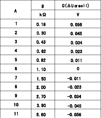
Injection timing adjustment Comp. resistor/voltage

Compensation resistance/compensation voltage comparison
A = Compensation resistor number
B= Compensation resistance
C = Compensation voltage delta U alpha soll
----------
----------
----------
----------
0000001601 HARNESS & CONNECTOR

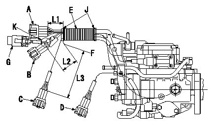
Corrugated tube assembly specification
(1)Do not fix D with corrugated tube.
(2)Maintain the corrugated tube so that the dimension of the end of the connector and the end of the corrugated are as shown in the figure.
(3)At K, pull the Q adjustment resistor towards the clip.
(4)Wrap black vinyl tape 4 times around the end of the corrugated tube to fix the tube.
A:RS08M-GY
B:RS06M-GY
C:RS03M-GY
D:RS03M-B
E:Corrugated tube
F:Tube end face
G:Q adjustment resistor
J:PVC tape
----------
----------
L1=40+-10mm L2=70+-10mm L3=150+-10mm
----------
----------
L1=40+-10mm L2=70+-10mm L3=150+-10mm
0000001701 HARNESS & CONNECTOR

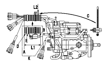
Injection quantity adjustment compensation resistor assembly standards
(1)Fix the injection quantity adjustment compensation resistor (Q adjustment resistor) using clips.
(2)After fixing the corrugated tube, and at the dimension L1 shown in the figure, fix the Q adjustment resistor so that it is positioned in the direction shown by the arrow in the figure (each connector clip side).
(3)Fix the Q adjustment harness's protective tube to the corrugated tube using black PVC tape.
(4)After confirming that the Q adjustment resistor is fixed in the position as shown by the arrow in diagram, cut off the excess clip to leave L2.
A:End of corrugated tube
B:Injection quantity adjustment compensation resistor (Q adjustment resistor)
C:After attaching the clip to the Q adjustment resistor, fix the corrugated tube.
D:Q adjustment resistor harness protective tube
E:PVC tape
K:Figure shown by arrow
----------
----------
L1=(120mm) L2=(5mm)
----------
----------
L1=(120mm) L2=(5mm)
Information:
The lubrication system consists of a sump (oil pan), oil pump, oil cooler and oil filter. The engine contains an oil manifold and oil passages to direct lubricant to the various components.The oil pump draws lubricant from the sump and forces it through the oil cooler, oil filter, and then into the oil manifold. Oil flows through connecting passages to lubricate the engine components. A regulating valve in the pump body controls the maximum pressure of the oil from the pump. When the engine is started, the lubricating oil in the oil pan is cool (thick). This cool viscous oil does not flow immediately through the oil cooler and oil filter. This cool oil forces bypass valves, in the oil cooler and oil filter base, to open allowing an unrestricted oil to flow through the engine.As oil temperature increases, oil viscosity and pressure decrease and the oil filter bypass valve closes. Now, only filtered oil is delivered to the engine components. Oil temperature continues to increase and the oil cooler bypass valve closes. Oil now flows through the oil cooler and oil filter before reaching the engine components.A contaminated or restricted oil filter element will not prevent lubricating oil from being delivered to the engine components. The oil filter bypass valve will open, allowing oil to bypass the element.An oil manifold, cast into the cylinder block, directs lubricant to the main bearings, valve rocker arm shafts, camshaft journals, and the camshaft idler (drive) gears.Oil spray orifices in the cylinder block spray oil on the underside of the pistons. This cools the pistons and provides lubricant for the piston pins, cylinder walls and piston rings.The connecting rod bearings receive oil through drilled passages in the crankshaft between the main bearing journals and connecting rod journals.When the engine is warm and running at rated speed, the oil pressure gauge should register in the "operating range". A lower pressure reading is normal at idling speeds.Many engines are equipped with an auxiliary or remote mounted bypass filter system. This system must be connected so part of the oil continuously circulates through the bypass filter, from the crankcase lubricating oil pump. An orifice on the outlet or clean side of the filter restricts the flow of oil through the bypass filter so full oil pressure is available to all parts of the engine. Filtered oil from the bypass filter is returned to the crankcase sump. Because of the additional oil capacity, extended change intervals can be established. See Lubrication Chart. The Bypass filter should never be used in place of the factory installed full flow filter.
Have questions with 104701-2021?
Group cross 104701-2021 ZEXEL
Nissan
Nissan
Nissan
104701-2021
9 460 611 108
167007F400
INJECTION-PUMP ASSEMBLY
TD27-T
TD27-T
