Information injection-pump assembly
ZEXEL
104701-2000
1047012000

Rating:
Cross reference number
ZEXEL
104701-2000
1047012000
Zexel num
Bosch num
Firm num
Name
104701-2000
INJECTION-PUMP ASSEMBLY
Calibration Data:
Adjustment conditions
Test oil
1404 Test oil ISO4113orSAEJ967d
1404 Test oil ISO4113orSAEJ967d
Test oil temperature
degC
45
45
50
Nozzle
105780-0060
Bosch type code
NP-DN0SD1510
Nozzle holder
105780-2150
Opening pressure
MPa
13
13
13.3
Opening pressure
kgf/cm2
133
133
136
Injection pipe
157805-7320
Injection pipe
Inside diameter - outside diameter - length (mm) mm 2-6-450
Inside diameter - outside diameter - length (mm) mm 2-6-450
Joint assembly
157641-4720
Tube assembly
157641-4020
Transfer pump pressure
kPa
20
20
20
Transfer pump pressure
kgf/cm2
0.2
0.2
0.2
Direction of rotation (viewed from drive side)
Right R
Right R
Governor adjustment
Pump speed
r/min
1000
1000
1000
TCV duty (%) F TCV 60Hz
%
100
100
100
U alpha soll
V
2.7
2.7
2.7
Pump chamber pressure
kPa
617.5
588
647
Pump chamber pressure
kgf/cm2
6.3
6
6.6
Basic
*
Governor adjustment_02
Pump speed
r/min
100
100
100
TCV duty (%) F TCV 60Hz
%
100
100
100
U alpha soll
V
2.7
2.7
2.7
Pump chamber pressure
kPa
294
294
Pump chamber pressure
kgf/cm2
3
3
Governor adjustment_03
Pump speed
r/min
1000
1000
1000
TCV duty (%) F TCV 60Hz
%
100
100
100
U alpha soll
V
2.7
2.7
2.7
Pump chamber pressure
kPa
618
579
657
Pump chamber pressure
kgf/cm2
6.3
5.9
6.7
Governor adjustment_04
Pump speed
r/min
2000
2000
2000
TCV duty (%) F TCV 60Hz
%
100
100
100
U alpha soll
V
2.7
2.7
2.7
Pump chamber pressure
kPa
755
706
804
Pump chamber pressure
kgf/cm2
7.7
7.2
8.2
Boost compensator adjustment
Pump speed
r/min
1000
1000
1000
TCV duty (%) F TCV 60Hz
%
70
70
70
U alpha soll
V
2.7
2.7
2.7
Timer stroke
mm
4.1
3.9
4.3
Basic
*
Boost compensator adjustment_02
Pump speed
r/min
500
500
500
TCV duty (%) F TCV 60Hz
%
100
100
100
U alpha soll
V
2.7
2.7
2.7
Timer stroke
mm
7.4
5.4
9.4
Boost compensator adjustment_03
Pump speed
r/min
1000
1000
1000
TCV duty (%) F TCV 60Hz
%
100
100
100
U alpha soll
V
2.7
2.7
2.7
Timer stroke
mm
8.1
6.1
10.1
Boost compensator adjustment_04
Pump speed
r/min
1000
1000
1000
TCV duty (%) F TCV 60Hz
%
70
70
70
U alpha soll
V
2.7
2.7
2.7
Timer stroke
mm
4.1
3.8
4.4
Boost compensator adjustment_05
Pump speed
r/min
1000
1000
1000
TCV duty (%) F TCV 60Hz
%
0
0
0
U alpha soll
V
2.7
2.7
2.7
Timer stroke
mm
0
0
0
Boost compensator adjustment_06
Pump speed
r/min
1500
1500
1500
TCV duty (%) F TCV 60Hz
%
100
100
100
U alpha soll
V
2.7
2.7
2.7
Timer stroke
mm
9.75
9.3
10.2
Speed control lever angle
Pump speed
r/min
1000
1000
1000
TCV duty (%) F TCV 60Hz
%
100
100
100
U alpha soll
V
2.7
2.7
2.7
Overflow quantity
cm3/min
600
470
730
0000000901
Pump speed
r/min
1000
1000
1000
U alpha soll + dU alpha soll
V
2.8
2.8
2.8
TCV duty (%) F TCV 60Hz
%
100
100
100
Average injection quantity
mm3/st.
80.5
80
81
Difference in delivery
mm3/st.
5
Basic
*
_02
Pump speed
r/min
375
375
375
U alpha soll + dU alpha soll
V
1.89
1.89
1.89
TCV duty (%) F TCV 60Hz
%
100
100
100
Average injection quantity
mm3/st.
7
4
10
Difference in delivery
mm3/st.
2
Basic
*
Remarks
Confirmation of difference in delivery
Confirmation of difference in delivery
_03
Pump speed
r/min
2500
2500
2500
U alpha soll + dU alpha soll
V
1.66
1.66
1.66
TCV duty (%) F TCV 60Hz
%
100
100
100
Average injection quantity
mm3/st.
16.1
13.6
18.6
Difference in delivery
mm3/st.
5
Basic
*
Remarks
Confirmation of difference in delivery
Confirmation of difference in delivery
_04
Pump speed
r/min
100
100
100
U alpha soll + dU alpha soll
V
3.5
3.5
3.5
TCV duty (%) F TCV 60Hz
%
100
100
100
Average injection quantity
mm3/st.
83.3
73.3
93.3
_05
Pump speed
r/min
375
375
375
U alpha soll + dU alpha soll
V
1.89
1.89
1.89
TCV duty (%) F TCV 60Hz
%
100
100
100
Average injection quantity
mm3/st.
7
4
10
_06
Pump speed
r/min
500
500
500
U alpha soll + dU alpha soll
V
2.49
2.49
2.49
TCV duty (%) F TCV 60Hz
%
100
100
100
Average injection quantity
mm3/st.
50.1
48.1
52.1
_07
Pump speed
r/min
800
800
800
U alpha soll + dU alpha soll
V
1.86
1.86
1.86
TCV duty (%) F TCV 60Hz
%
100
100
100
Average injection quantity
mm3/st.
15.4
13.4
17.4
_08
Pump speed
r/min
800
800
800
U alpha soll + dU alpha soll
V
2.62
2.62
2.62
TCV duty (%) F TCV 60Hz
%
100
100
100
Average injection quantity
mm3/st.
64.4
62.4
66.4
_09
Pump speed
r/min
1000
1000
1000
U alpha soll + dU alpha soll
V
1.85
1.85
1.85
TCV duty (%) F TCV 60Hz
%
100
100
100
Average injection quantity
mm3/st.
16.6
14.6
18.6
_10
Pump speed
r/min
1000
1000
1000
U alpha soll + dU alpha soll
V
2.8
2.8
2.8
TCV duty (%) F TCV 60Hz
%
100
100
100
Average injection quantity
mm3/st.
80.5
79.5
81.5
_11
Pump speed
r/min
2000
2000
2000
U alpha soll + dU alpha soll
V
2.58
2.58
2.58
TCV duty (%) F TCV 60Hz
%
100
100
100
Average injection quantity
mm3/st.
63.7
61.7
65.7
_12
Pump speed
r/min
2250
2250
2250
U alpha soll + dU alpha soll
V
2.43
2.43
2.43
TCV duty (%) F TCV 60Hz
%
100
100
100
Average injection quantity
mm3/st.
54.3
51.8
56.8
_13
Pump speed
r/min
2500
2500
2500
U alpha soll + dU alpha soll
V
1.66
1.66
1.66
TCV duty (%) F TCV 60Hz
%
100
100
100
Average injection quantity
mm3/st.
16.1
13.6
18.6
_14
Pump speed
r/min
2500
2500
2500
U alpha soll + dU alpha soll
V
1
1
1
TCV duty (%) F TCV 60Hz
%
100
100
100
Average injection quantity
mm3/st.
3
Stop lever angle
Pump speed
r/min
375
375
375
U alpha soll + dU alpha soll
V
1.89
1.89
1.89
TCV duty (%) F TCV 60Hz
%
0
0
0
Average injection quantity
cm3/min
0
0
0
Stop lever angle_02
Pump speed
r/min
2250
2250
2250
U alpha soll + dU alpha soll
V
2.43
2.43
2.43
TCV duty (%) F TCV 60Hz
%
100
100
100
Average injection quantity
cm3/min
0
0
0
0000001101
Pump speed
r/min
200
200
200
TCV duty (%) F TCV 60Hz
%
100
100
100
U alpha soll
V
2.7
2.7
2.7
Speed output
N=Measure the actual speed. r/min N+-8
N=Measure the actual speed. r/min N+-8
0000001201
Pump speed
r/min
1000
1000
1000
TCV duty (%) F TCV 60Hz
%
100
100
100
U alpha soll
V
2.8
2.8
2.8
Temperature output
Measure T = actual output temperature degC T+-5
Measure T = actual output temperature degC T+-5
0000001301
Max. applied voltage
V
8
8
8
Test voltage
V
13
12
14
0000001401
K dimension
mm
3.3
3.2
3.4
KF dimension
mm
5.62
5.52
5.72
Pre-stroke
mm
0.1
0.08
0.12
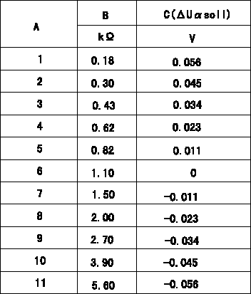
Test data Ex:
Injection timing adjustment Comp. resistor/voltage

Compensation resistance/compensation voltage comparison
A = Compensation resistor number
B= Compensation resistance
C = Compensation voltage delta U alpha soll
----------
----------
----------
----------
Information:
Table 1
Part Number Part Description Qty
378-3187 Diesel Exhaust Fluid Filter Gp 1
423-3251 Connector 1
391-5262 Gasket 1
425-0385 Filter As 1
452-6055 Filter Base As 1
453-1604(1) Diesel Exhaust Fluid Filter Gp 1
453-1605(1) Diesel Exhaust Fluid Filter Gp 1
453-1606(1) Diesel Exhaust Fluid Filter Gp 1
(1) Use Table 2 to choose the correct part that corresponds to the DEF heater
Table 2
DEF Heater Part Number Required DEF Filter
434-3241 453-1604
434-3242 453-1605
434-3243 453-1606 The effective serial numbers for this change are related to the Pump Electronic Tank Unit (PETU) serial numbers and not the machine serial numbers. Table 3 contains the effective serial numbers for the PETU tank. Refer to illustration 1 and illustration 2 for examples of where to locate the PETU serial number.
Illustration 1 g06018843
Typical example
(1) The location of the PETU serial plate.
Illustration 2 g03418749
Typical example
Table 3
PETU Effective Serial Numbers
S/N:PET007086T-UP Refer to Special Instruction, M0066142, A New Diesel Exhaust Fluid Filter is Now Available for C7.1 Engines for installation instructions.
Have questions with 104701-2000?
Group cross 104701-2000 ZEXEL
104701-2000
INJECTION-PUMP ASSEMBLY