Information injection-pump assembly
BOSCH
9 460 614 250
9460614250
ZEXEL
104700-9170
1047009170
Rating:
Components :
| 0. | INJECTION-PUMP ASSEMBLY | 104700-9170 |
| 1. | _ | |
| 2. | FUEL INJECTION PUMP | 104600-9170 |
| 3. | NUMBER PLATE | 148643-2300 |
| 4. | _ | |
| 5. | CAPSULE | |
| 6. | ADJUSTING DEVICE | |
| 7. | NOZZLE AND HOLDER ASSY | |
| 8. | Nozzle and Holder | |
| 9. | Open Pre:MPa(Kqf/cm2) | |
| 10. | NOZZLE-HOLDER | |
| 11. | NOZZLE |
Scheme ###:
| 1/6. | [1] | 146601-0700 | PACKING RING |
| 6. | [1] | 146100-0120 | SUPPLY PUMP |
| 9. | [1] | 148103-0400 | COVER |
| 10. | [2] | 139104-0000 | FLAT-HEAD SCREW |
| 12. | [1] | 148200-0520 | DRIVE SHAFT |
| 12/3. | [1] | 146201-0000 | WOODRUFF KEY |
| 17. | [1] | 146204-0000 | PLAIN WASHER |
| 20. | [1] | 148210-0120 | ROLLER SET |
| 24. | [1] | 146303-0000 | BEARING PIN |
| 25. | [1] | 146304-0000 | BEARING PIN |
| 26. | [1] | 146305-0000 | CLAMPING BAND |
| 27. | [1] | 146205-0000 | SLOTTED WASHER |
| 29. | [1] | 146220-2120 | CAM PLATE |
| 30. | [1] | 146600-0800 | O-RING |
| 31. | [1] | 146300-1900 | PUMP PLUNGER |
| 32. | [1] | 146301-0000 | SLIDING PIECE |
| 33. | [1] | 146603-1100 | SHIM D17.5&7.5T1.20 |
| 34. | [1] | 146306-1800 | COMPRESSION SPRING |
| 34B. | [1] | 146306-2100 | COMPRESSION SPRING |
| 35/1. | [0] | 146603-0700 | SHIM D17.5&7.5T0.60 |
| 35/1. | [0] | 146603-0800 | SHIM D17.5&7.5T0.70 |
| 35/1. | [0] | 146603-0900 | SHIM D17.5&7.5T0.90 |
| 35/1. | [0] | 146603-1000 | SHIM D17.5&7.5T1.00 |
| 35/1. | [0] | 146603-1100 | SHIM D17.5&7.5T1.20 |
| 35/1. | [0] | 146603-3600 | SHIM D17.5&7.5T2.40 |
| 36. | [1] | 146600-0800 | O-RING |
| 37. | [1] | 479766-4320 | TIMER PISTON SENSOR |
| 38. | [2] | 146622-1200 | HEX-SOCKET-HEAD CAP SCREW |
| 39. | [1] | 146310-5600 | COVER |
| 40. | [2] | 146622-1300 | BLEEDER SCREW |
| 43. | [1] | 146230-0000 | SHIM |
| 44. | [1] | 146230-0100 | PLAIN WASHER |
| 45. | [1] | 146231-0001 | SLOTTED WASHER |
| 47. | [2] | 146233-0000 | SLOTTED WASHER |
| 48/1. | [1] | 146603-0000 | SHIM D17.0&5.2T0.50 |
| 48/1. | [1] | 146603-0100 | SHIM D17.0&5.2T0.80 |
| 48/1. | [1] | 146603-0200 | SHIM D17.0&5.2T1.00 |
| 48/1. | [1] | 146603-0300 | SHIM D17.0&5.2T1.20 |
| 48/1. | [1] | 146603-0400 | SHIM D17.0&5.2T1.50 |
| 48/1. | [1] | 146603-0500 | SHIM D17.0&5.2T1.80 |
| 48/1. | [1] | 146603-0600 | SHIM D17.0&5.2T2.00 |
| 48/1. | [1] | 146690-1400 | SHIM D17&5.2T0.9 |
| 48/1. | [1] | 146690-1500 | SHIM D17&5.2T1.1 |
| 48/1. | [1] | 146690-1600 | SHIM D17&5.2T1.3 |
| 48/1. | [1] | 146690-1700 | SHIM D17&5.2T1.4 |
| 48/1. | [1] | 146690-1800 | SHIM D17&5.2T1.6 |
| 48/1. | [1] | 146690-1900 | SHIM D17&5.2T1.7 |
| 48/1. | [1] | 146690-5800 | SHIM D17&5.2T2.1 |
| 48/1. | [1] | 146690-5900 | SHIM D17&5.2T2.2 |
| 48/1. | [1] | 146690-6000 | SHIM D17&5.2T2.3 |
| 48/1. | [1] | 146690-6100 | SHIM D17&5.2T2.4 |
| 48/1. | [1] | 146690-6200 | SHIM D17&5.2T2.5 |
| 48/1. | [1] | 146690-6300 | SHIM D17&5.2T2.6 |
| 48/1. | [1] | 146690-6400 | SHIM D17&5.2T2.7 |
| 48/1. | [1] | 146690-6500 | SHIM D17&5.2T2.8 |
| 48/1. | [1] | 146690-6600 | SHIM D17&5.2T2.9 |
| 48/1. | [1] | 146690-6700 | SHIM D17&5.2T3.0 |
| 48/1. | [1] | 146690-6800 | SHIM D17&5.2T3.1 |
| 48/1. | [1] | 146690-6900 | SHIM D17&5.2T3.2 |
| 48/1. | [1] | 146690-7000 | SHIM D17&5.2T3.3 |
| 48/1. | [1] | 146690-7100 | SHIM D17&5.2T3.4 |
| 48/1. | [1] | 146690-7200 | SHIM D17&5.2T0.4 |
| 48/1. | [1] | 146690-7300 | SHIM D17&5.2T0.6 |
| 48/1. | [1] | 146690-7400 | SHIM D17&5.2T0.7 |
| 48/1. | [1] | 146690-7500 | SHIM D17&5.2T1.9 |
| 48/1. | [1] | 146690-7800 | SHIM D17&5.2T0.2 |
| 49. | [2] | 146234-0500 | GUIDE PIN |
| 50. | [1] | 146403-9620 | HYDRAULIC HEAD |
| 50. | [1] | 146403-9620 | HYDRAULIC HEAD |
| 50. | [1] | 146403-9620 | HYDRAULIC HEAD |
| 51. | [1] | 146600-0000 | O-RING |
| 52/1. | [1] | 146420-0000 | SHIM D9.5&3.0T1.90 |
| 52/1. | [1] | 146420-0100 | SHIM D9.5&3.0T1.92 |
| 52/1. | [1] | 146420-0200 | SHIM D9.5&3.0T1.94 |
| 52/1. | [1] | 146420-0300 | SHIM D9.5&3.0T1.96 |
| 52/1. | [1] | 146420-0400 | SHIM D9.5&3.0T1.98 |
| 52/1. | [1] | 146420-0500 | SHIM D9.5&3.0T2.00 |
| 52/1. | [1] | 146420-0600 | SHIM D9.5&3.0T2.02 |
| 52/1. | [1] | 146420-0700 | SHIM D9.5&3.0T2.04 |
| 52/1. | [1] | 146420-0800 | SHIM D9.5&3.0T2.06 |
| 52/1. | [1] | 146420-0900 | SHIM D9.5&3.0T2.08 |
| 52/1. | [1] | 146420-1000 | SHIM D9.5&3.0T2.10 |
| 52/1. | [1] | 146420-1100 | SHIM D9.5&3.0T2.12 |
| 52/1. | [1] | 146420-1200 | SHIM D9.5&3.0T2.14 |
| 52/1. | [1] | 146420-1300 | SHIM D9.5&3.0T2.16 |
| 52/1. | [1] | 146420-1400 | SHIM D9.5&3.0T2.18 |
| 52/1. | [1] | 146420-1500 | SHIM D9.5&3.0T2.20 |
| 52/1. | [1] | 146420-1600 | SHIM D9.5&3.0T2.22 |
| 52/1. | [1] | 146420-1700 | SHIM D9.5&3.0T2.24 |
| 52/1. | [1] | 146420-1800 | SHIM D9.5&3.0T2.26 |
| 52/1. | [1] | 146420-1900 | SHIM D9.5&3.0T2.28 |
| 52/1. | [1] | 146420-2000 | SHIM D9.5&3.0T2.30 |
| 52/1. | [1] | 146420-2100 | SHIM D9.5&3.0T2.32 |
| 52/1. | [1] | 146420-2200 | SHIM D9.5&3.0T2.34 |
| 52/1. | [1] | 146420-2300 | SHIM D9.5&3.0T2.36 |
| 52/1. | [1] | 146420-2400 | SHIM D9.5&3.0T2.38 |
| 52/1. | [1] | 146420-2500 | SHIM D9.5&3.0T2.40 |
| 52/1. | [1] | 146420-2600 | SHIM D9.5&3.0T2.42 |
| 52/1. | [1] | 146420-2700 | SHIM D9.5&3.0T2.44 |
| 52/1. | [1] | 146420-2800 | SHIM D9.5&3.0T2.46 |
| 52/1. | [1] | 146420-2900 | SHIM D9.5&3.0T2.48 |
| 52/1. | [1] | 146420-3000 | SHIM D9.5&3.0T2.50 |
| 52/1. | [1] | 146420-3100 | SHIM D9.5&3.0T2.52 |
| 52/1. | [1] | 146420-3200 | SHIM D9.5&3.0T2.54 |
| 52/1. | [1] | 146420-3300 | SHIM D9.5&3.0T2.56 |
| 52/1. | [1] | 146420-3400 | SHIM D9.5&3.0T2.58 |
| 52/1. | [1] | 146420-3500 | SHIM D9.5&3.0T2.60 |
| 52/1. | [1] | 146420-3600 | SHIM D9.5&3.0T2.62 |
| 52/1. | [1] | 146420-3700 | SHIM D9.5&3.0T2.64 |
| 52/1. | [1] | 146420-3800 | SHIM D9.5&3.0T2.66 |
| 52/1. | [1] | 146420-3900 | SHIM D9.5&3.0T2.68 |
| 52/1. | [1] | 146420-4000 | SHIM D9.5&3.0T2.70 |
| 52/1. | [1] | 146420-4100 | SHIM D9.5&3.0T2.72 |
| 52/1. | [1] | 146420-4200 | SHIM D9.5&3.0T2.74 |
| 52/1. | [1] | 146420-4300 | SHIM D9.5&3.0T2.76 |
| 52/1. | [1] | 146420-4400 | SHIM D9.5&3.0T2.78 |
| 52/1. | [1] | 146420-4500 | SHIM D9.5&3.0T2.80 |
| 52/1. | [1] | 146420-4600 | SHIM D9.5&3.0T2.82 |
| 52/1. | [1] | 146420-4700 | SHIM D9.5&3.0T2.84 |
| 52/1. | [1] | 146420-4800 | SHIM D9.5&3.0T2.86 |
| 52/1. | [1] | 146420-4900 | SHIM D9.5&3.0T2.88 |
| 52/1. | [1] | 146420-5000 | SHIM D9.5&3.0T2.90 |
| 52/1. | [1] | 146420-5100 | SHIM D9.5&3.0T1.74 |
| 52/1. | [1] | 146420-5200 | SHIM D9.5&3.0T1.76 |
| 52/1. | [1] | 146420-5300 | SHIM D9.5&3.0T1.78 |
| 52/1. | [1] | 146420-5400 | SHIM D9.5&3.0T1.80 |
| 52/1. | [1] | 146420-5500 | SHIM D9.5&3.0T1.82 |
| 52/1. | [1] | 146420-5600 | SHIM D9.5&3.0T1.84 |
| 52/1. | [1] | 146420-5700 | SHIM D9.5&3.0T1.86 |
| 52/1. | [1] | 146420-5800 | SHIM D9.5&3.0T1.88 |
| 54. | [4] | 146433-0100 | GASKET D12&6.4T1.00 |
| 55. | [4] | 146430-0320 | DELIVERY-VALVE ASSEMBLY |
| 56. | [4] | 146432-0000 | COMPRESSION SPRING |
| 58. | [4] | 146440-3220 | FITTING |
| 60. | [3] | 146622-1800 | FLAT-HEAD SCREW |
| 123. | [1] | 146622-0900 | FLAT-HEAD SCREW |
| 130. | [1] | 146421-1920 | CAPSULE |
| 130/2. | [1] | 139508-0200 | GASKET D11.4&8.2T1 |
| 130/3. | [1] | 146422-0700 | BLEEDER SCREW |
| 130/4. | [1] | 146600-0500 | O-RING |
| 133. | [1] | 146600-0600 | O-RING |
| 134. | [1] | 146600-0700 | O-RING |
| 135. | [1] | 146110-3520 | CONTROL VALVE |
| 135/5. | [1] | 146114-0000 | SPRING WASHER |
| 136. | [1] | 148120-0320 | OVER FLOW VALVE |
| 137. | [3] | 139512-0500 | GASKET |
| 138. | [1] | 146669-5821 | INLET UNION |
| 140. | [4] | 148650-3100 | CAP |
| 158. | [1] | 146663-5500 | SPACER BUSHING |
| 200. | [1] | 146206-0100 | COILED SPRING |
| 205. | [1] | 029470-4030 | WOODRUFF KEY |
| 230. | [1] | 148613-6620 | BRACKET |
| 236. | [1] | 146622-1400 | HEX-SOCKET-HEAD CAP SCREW |
| 237. | [1] | 146622-1500 | HEX-SOCKET-HEAD CAP SCREW |
| 240. | [1] | 146688-3720 | PULLING ELECTROMAGNET |
| 240/8. | [1] | 146600-1700 | O-RING |
| 243. | [1] | 146621-1000 | UNION NUT |
| 245. | [3] | 139512-0500 | GASKET |
| 246. | [1] | 146125-1000 | EYE BOLT |
| 247. | [1] | 146677-6520 | INLET UNION |
| 248. | [1] | 146663-5600 | SPACER BUSHING |
| 275. | [1] | 148612-1600 | BRACKET |
| 276. | [2] | 146622-1700 | BLEEDER SCREW |
| 278. | [2] | 146663-5700 | SPACER BUSHING |
| 282. | [1] | 146622-1900 | BLEEDER SCREW |
| 504/1. | [1] | 146649-4500 | RESISTER |
| 504/1. | [1] | 146649-4600 | RESISTER |
| 504/1. | [1] | 146649-4700 | RESISTER |
| 504/1. | [1] | 146649-4800 | RESISTER |
| 504/1. | [1] | 146649-4900 | RESISTER |
| 504/1. | [1] | 146649-5000 | RESISTER |
| 504/1. | [1] | 146649-5100 | RESISTER |
| 504/1. | [1] | 146649-5200 | RESISTER |
| 504/1. | [1] | 146649-5300 | RESISTER |
| 504/1. | [1] | 146649-5400 | RESISTER |
| 504/1. | [1] | 146649-5500 | RESISTER |
| 504/1. | [1] | 146649-5600 | RESISTER |
| 504/1. | [1] | 146649-5700 | RESISTER |
| 505. | [1] | 148530-4620 | GOVERNOR;ELECTRIC |
| 506. | [3] | 146622-1000 | FLAT-HEAD SCREW |
| 515. | [1] | 106144-1071 | TIMING CONTROL VALVE |
| 515/7. | [1] | 161440-3800 | O-RING |
| 515/8. | [1] | 161440-3700 | O-RING |
| 516. | [2] | 146622-1600 | HEX-SOCKET-HEAD CAP SCREW |
| 531. | [1] | 479766-4120 | PULSE GENERATOR |
| 536. | [1] | 148650-4200 | TUBE |
| 551. | [1] | 146659-9501 | CLAMPING BAND |
| 552. | [1] | 014110-8442 | LOCKING WASHER |
| 553. | [1] | 010208-1242 | HEX-SOCKET-HEAD CAP SCREW |
| 800S. | [1] | 148009-0620 | PUMP HOUSING |
| 800S/1/6. | [1] | 146601-0700 | PACKING RING |
| 804S. | [1] | 146232-0320 | COMPRESSION SPRING |
| 810S. | [1] | 146600-4620 | REPAIR SET |
| 821S. | [1] | 146210-5720 | ROLLER SET |
| 878S. | [1] | 148600-1300 | SEAL RING |
| 906. | [1] | 148643-2300 | NAMEPLATE |
Include in #2:
104700-9170
as INJECTION-PUMP ASSEMBLY
Cross reference number
BOSCH
9 460 614 250
9460614250
ZEXEL
104700-9170
1047009170
Zexel num
Bosch num
Firm num
Name
Calibration Data:
Adjustment conditions
Test oil
1404 Test oil ISO4113orSAEJ967d
1404 Test oil ISO4113orSAEJ967d
Test oil temperature
degC
45
45
50
Nozzle
105780-0060
Bosch type code
NP-DN0SD1510
Nozzle holder
105780-2150
Opening pressure
MPa
13
13
13.3
Opening pressure
kgf/cm2
133
133
136
Injection pipe
157805-7320
Injection pipe
Inside diameter - outside diameter - length (mm) mm 2-6-450
Inside diameter - outside diameter - length (mm) mm 2-6-450
Joint assembly
157641-4720
Tube assembly
157641-4020
Transfer pump pressure
kPa
20
20
20
Transfer pump pressure
kgf/cm2
0.2
0.2
0.2
Direction of rotation (viewed from drive side)
Right R
Right R
Governor adjustment
Pump speed
r/min
1000
1000
1000
TCV duty (%) F TCV 60Hz
%
100
100
100
U alpha soll
V
2.7
2.7
2.7
Pump chamber pressure
kPa
598
569
627
Pump chamber pressure
kgf/cm2
6.1
5.8
6.4
Basic
*
Governor adjustment_02
Pump speed
r/min
100
100
100
TCV duty (%) F TCV 60Hz
%
100
100
100
U alpha soll
V
2.7
2.7
2.7
Pump chamber pressure
kPa
294
294
Pump chamber pressure
kgf/cm2
3
3
Governor adjustment_03
Pump speed
r/min
1000
1000
1000
TCV duty (%) F TCV 60Hz
%
100
100
100
U alpha soll
V
2.7
2.7
2.7
Pump chamber pressure
kPa
598
559
637
Pump chamber pressure
kgf/cm2
6.1
5.7
6.5
Governor adjustment_04
Pump speed
r/min
2000
2000
2000
TCV duty (%) F TCV 60Hz
%
100
100
100
U alpha soll
V
2.7
2.7
2.7
Pump chamber pressure
kPa
735
686
784
Pump chamber pressure
kgf/cm2
7.5
7
8
Boost compensator adjustment
Pump speed
r/min
1000
1000
1000
TCV duty (%) F TCV 60Hz
%
100
100
100
U alpha soll
V
2.7
2.7
2.7
Timer stroke
mm
7.7
7.5
7.9
Basic
*
Boost compensator adjustment_02
Pump speed
r/min
100
100
100
TCV duty (%) F TCV 60Hz
%
100
100
100
U alpha soll
V
2.7
2.7
2.7
Timer stroke
mm
1.8
0.3
3.3
Boost compensator adjustment_03
Pump speed
r/min
350
350
350
TCV duty (%) F TCV 60Hz
%
100
100
100
U alpha soll
V
2.7
2.7
2.7
Timer stroke
mm
5.2
3.1
7.3
Boost compensator adjustment_04
Pump speed
r/min
1000
1000
1000
TCV duty (%) F TCV 60Hz
%
100
100
100
U alpha soll
V
2.7
2.7
2.7
Timer stroke
mm
7.7
7.4
8
Boost compensator adjustment_05
Pump speed
r/min
1000
1000
1000
TCV duty (%) F TCV 60Hz
%
70
70
70
U alpha soll
V
2.7
2.7
2.7
Timer stroke
mm
4
1.9
6.1
Boost compensator adjustment_06
Pump speed
r/min
2000
2000
2000
TCV duty (%) F TCV 60Hz
%
100
100
100
U alpha soll
V
2.7
2.7
2.7
Timer stroke
mm
9.75
9.3
10.2
Boost compensator adjustment_07
Pump speed
r/min
2000
2000
2000
TCV duty (%) F TCV 60Hz
%
0
0
0
U alpha soll
V
2.7
2.7
2.7
Timer stroke
mm
0
0
0
Timer adjustment
Pump speed
r/min
1000
1000
1000
TCV duty (%) F TCV 60Hz
%
0
0
0
U alpha soll
V
2.7
2.7
2.7
Vtps
V
0.51
0.382
0.638
Basic
*
Timer adjustment_02
Pump speed
r/min
1000
1000
1000
TCV duty (%) F TCV 60Hz
%
0
0
0
U alpha soll
V
2.7
2.7
2.7
Vtps
V
0.51
0.382
0.638
Timer adjustment_03
Pump speed
r/min
1000
1000
1000
TCV duty (%) F TCV 60Hz
%
100
100
100
U alpha soll
V
2.7
2.7
2.7
Vtps
V
1.925
1.702
2.148
Speed control lever angle
Pump speed
r/min
1000
1000
1000
TCV duty (%) F TCV 60Hz
%
100
100
100
U alpha soll
V
2.7
2.7
2.7
Overflow quantity
cm3/min
550
420
680
0000000901
Pump speed
r/min
1250
1250
1250
U alpha soll + dU alpha soll
V
2.86
2.86
2.86
TCV duty (%) F TCV 60Hz
%
100
100
100
Average injection quantity
mm3/st.
72
71.5
72.5
Difference in delivery
mm3/st.
3.5
Basic
*
_02
Pump speed
r/min
375
375
375
U alpha soll + dU alpha soll
V
2
2
2
TCV duty (%) F TCV 60Hz
%
100
100
100
Average injection quantity
mm3/st.
14.8
11.8
17.8
Difference in delivery
mm3/st.
2.5
Basic
*
Remarks
Confirmation of difference in delivery
Confirmation of difference in delivery
_03
Pump speed
r/min
2575
2575
2575
U alpha soll + dU alpha soll
V
1.96
1.96
1.96
TCV duty (%) F TCV 60Hz
%
100
100
100
Average injection quantity
mm3/st.
20.3
17.8
22.8
Difference in delivery
mm3/st.
5.5
Basic
*
Remarks
Confirmation of difference in delivery
Confirmation of difference in delivery
_04
Pump speed
r/min
100
100
100
U alpha soll + dU alpha soll
V
3.31
3.31
3.31
TCV duty (%) F TCV 60Hz
%
100
100
100
Average injection quantity
mm3/st.
67.9
57.9
77.9
_05
Pump speed
r/min
375
375
375
U alpha soll + dU alpha soll
V
2
2
2
TCV duty (%) F TCV 60Hz
%
100
100
100
Average injection quantity
mm3/st.
14.8
11.8
17.8
_06
Pump speed
r/min
500
500
500
U alpha soll + dU alpha soll
V
2.74
2.74
2.74
TCV duty (%) F TCV 60Hz
%
100
100
100
Average injection quantity
mm3/st.
51.2
48.7
53.7
_07
Pump speed
r/min
750
750
750
U alpha soll + dU alpha soll
V
2.83
2.83
2.83
TCV duty (%) F TCV 60Hz
%
100
100
100
Average injection quantity
mm3/st.
63.1
60.6
65.6
_08
Pump speed
r/min
1000
1000
1000
U alpha soll + dU alpha soll
V
2.87
2.87
2.87
TCV duty (%) F TCV 60Hz
%
100
100
100
Average injection quantity
mm3/st.
70.4
67.9
72.9
_09
Pump speed
r/min
1250
1250
1250
U alpha soll + dU alpha soll
V
2.86
2.86
2.86
TCV duty (%) F TCV 60Hz
%
100
100
100
Average injection quantity
mm3/st.
72
71
73
_10
Pump speed
r/min
1500
1500
1500
U alpha soll + dU alpha soll
V
2.82
2.82
2.82
TCV duty (%) F TCV 60Hz
%
100
100
100
Average injection quantity
mm3/st.
68.6
66.1
71.1
_11
Pump speed
r/min
1750
1750
1750
U alpha soll + dU alpha soll
V
2.8
2.8
2.8
TCV duty (%) F TCV 60Hz
%
100
100
100
Average injection quantity
mm3/st.
65.5
63
68
_12
Pump speed
r/min
1900
1900
1900
U alpha soll + dU alpha soll
V
2.77
2.77
2.77
TCV duty (%) F TCV 60Hz
%
100
100
100
Average injection quantity
mm3/st.
63.8
61.3
66.3
_13
Pump speed
r/min
2575
2575
2575
U alpha soll + dU alpha soll
V
1.96
1.96
1.96
TCV duty (%) F TCV 60Hz
%
100
100
100
Average injection quantity
mm3/st.
20.3
17.8
22.8
_14
Pump speed
r/min
2575
2575
2575
U alpha soll + dU alpha soll
V
1
1
1
TCV duty (%) F TCV 60Hz
%
100
100
100
Average injection quantity
mm3/st.
3
Stop lever angle
Pump speed
r/min
1900
1900
1900
U alpha soll + dU alpha soll
V
2.77
2.77
2.77
TCV duty (%) F TCV 60Hz
%
100
100
100
Average injection quantity
cm3/min
0
0
0
0000001101
Pump speed
r/min
200
200
200
TCV duty (%) F TCV 60Hz
%
100
100
100
U alpha soll
V
2.7
2.7
2.7
Speed output
N=Measure the actual speed. r/min N+-8
N=Measure the actual speed. r/min N+-8
0000001201
Pump speed
r/min
1250
1250
1250
TCV duty (%) F TCV 60Hz
%
100
100
100
U alpha soll
V
2.73
2.73
2.73
Temperature output
Measure T = actual output temperature degC T+-5
Measure T = actual output temperature degC T+-5
0000001301
Max. applied voltage
V
8
8
8
Test voltage
V
13
12
14
0000001401
K dimension
mm
3.3
3.2
3.4
KF dimension
mm
5.8
5.7
5.9
Pre-stroke
mm
0.1
0.08
0.12
Test data Ex:
Injection timing adjustment Comp. resistor/voltage
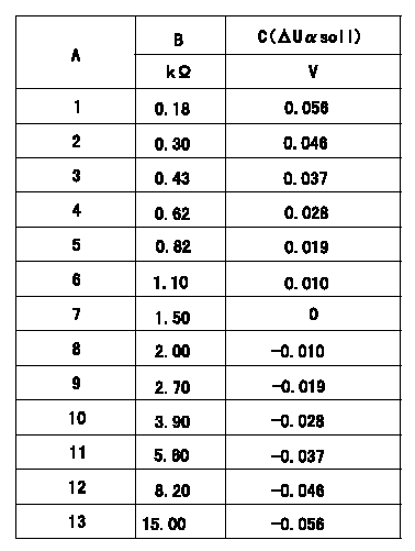
Compensation resistance/compensation voltage comparison
A = Compensation resistor number
B= Compensation resistance
C = Compensation voltage delta U alpha soll
----------
----------
----------
----------
0000001601 HARNESS & CONNECTOR
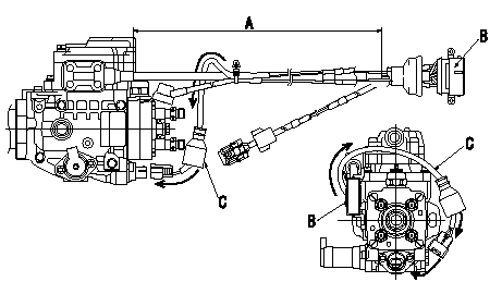
T.C.V. connector assembly specification
(1)Ensure the GE cable is not twisted at section A.
(2)Refer to diagram for direction of connector B.
(3)Route the TCV harnes C in the direction indicated by the arrows in the figure and install the connector.
----------
----------
----------
----------
0000001701 HARNESS & CONNECTOR
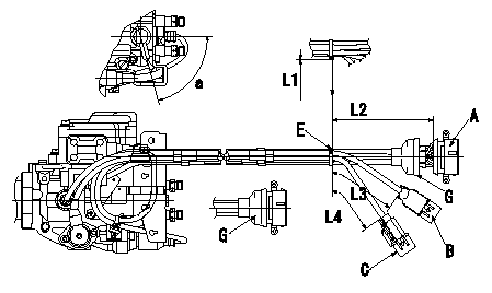
Harness position specification
(1)Ensure each dimension is as shown in the diagram and fix the harness using the binders.
(2)Cut the binder leaving no more than L1 excess.
(3)Attach cover G to the GE, FCV, TCV and Q adjustment connectors.
(4)After completing all of the procedures, ensure no lead wires are exposed after routing the harness.
A = GE, FCV, TCV, Q adjustment
B=NP
C=TPS
E = binder
G=Cover
----------
----------
a=(75deg) L1=Max.2mm L2=300+-10mm L3=235+11-9mm L4=225+11-9mm
----------
----------
a=(75deg) L1=Max.2mm L2=300+-10mm L3=235+11-9mm L4=225+11-9mm
0000001801 HARNESS & CONNECTOR
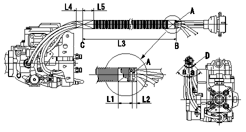
Corrugated tube assembly specification
(1)Align the end of the corrugated tube with clip A and fix it using black vinyl tape (L1, L2).
(2)Confirm that the dimension to the end of the corrugated tube C is L3, and fix it using black vinyl tape (L4, L5).
(3)Refer to the illustration for the position of the corrugated tube slit.
A = binder
B = outside edge of binder
C = end of corrugated tube
D = position of corrugated tube's slit
----------
----------
L1=Max.25mm L2=Max.10mm L3=285+-10mm L4=(20mm) L5=(30mm) a=45deg
----------
----------
L1=Max.25mm L2=Max.10mm L3=285+-10mm L4=(20mm) L5=(30mm) a=45deg
0000001901 HARNESS & CONNECTOR
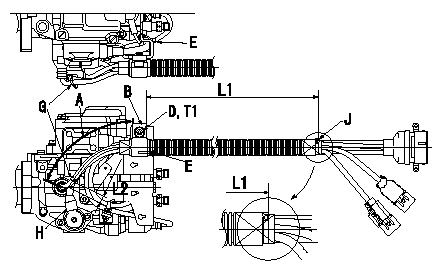
Harness fixing specification
(1)Make the clearance between the clip J and the clip (B with metal end face) L1.
(2)Fix clip B using socket head bolt D. At this time, adjust to within the tolerance L1 so that the TPS and NP harnesses in section A do not have excessive slack.
(3)Clip the GE cable and the FCV harness using clip E, and the TPS-NP harness using clip G.
(4)Attach the binder G after ensuring that the TPS cover H is not loose.
B = clip
D = socket head bolt
E = binder
G=Binder
H = TPS cover
J = binder
----------
----------
L1=260+-10mm L2=5~15mm T1=9.8~13.7N-m(1.0~1.4kgf-m)
----------
----------
L1=260+-10mm L2=5~15mm T1=9.8~13.7N-m(1.0~1.4kgf-m)
0000002001 HARNESS & CONNECTOR
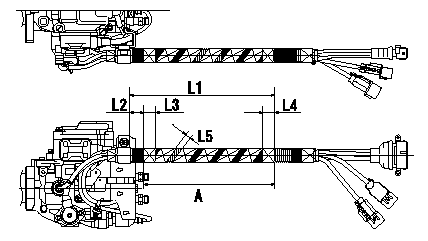
Vinyl tape assembly specification
Wrap with vinyl tape at position A in the figure.
----------
----------
L1=190+-10mm L2=25+-10mm L3=(20mm) L4=(20mm) L5=(10mm)
----------
----------
L1=190+-10mm L2=25+-10mm L3=(20mm) L4=(20mm) L5=(10mm)
0000002101 HARNESS & CONNECTOR
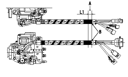
Marking application specification
(1)Ensure the corrugated tube is not twisted and then mark the position A shown in the figure.
(2)3) Mark at the two locations indicated in the figure ( viewed from the side of the pump and the top of the pump). The markings must be the dimensions shown and approx. 5 mm wide.
(3)2) Use indelible paint for steel.
A = white marking
B = End of tape binding
----------
----------
L1=20+-5mm
----------
----------
L1=20+-5mm
Information:
Table 15
CDL Diagnostic
Sensor Description DTC CID FMI Harness Pin Number Harness Connector
Fuel Supply Flow Rotor Speed Sensor 1 4515 10 and 14 J1-6 A-C2
Fuel Supply Flow Rotor Speed Sensor 2 4516 8 J1-52 A-C3
Fuel Return Flow Rotor Speed Sensor 1 4517 10 and 14 J1-61 C-C2
Fuel Return Flow Rotor Speed Sensor 2 4518 8 J1-63 C-C3 If the fuel volume speed sensor detects an abnormal rate of change, a diagnostic of FMI 10, "Abnormal Rate of Change", will be reported on the SAE J1939 data link and the CDL data link for the errant sensor. An "Abnormal Rate of Change" will be detected when the measured frequency is greater than the maximum flow rate for which the transducer is rated.If the fuel volume speed sensor detects an abnormal frequency, pulse width or period, a diagnostic of FMI 8, "Abnormal Frequency, Pulse Width or Period", will be reported on the SAE J1939 data link and the CDL data link for the errant sensor. This indicates a loose or pinched wire or an errant speed sensor. An abnormal frequency, pulse width, or period will be detected if the frequency reading indicates that the transducer has been installed backwards.If the fuel volume speed sensor outputs a flow rate of 160 pps or more, a diagnostic with FMI 14 will be reported on the SAE J1939 data link and the CDL. This indicates that the flow rate through the transducer is approaching the maximum flow rate.Temperature Sensor Diagnostic Indicators
If a temperature sensor fails, the ECM raises a diagnostic message and sends it on the main SAE J1939 data link and the CDL bus.
Table 16
Sensor Description SAE J1939 SPN CDL DTC CID Harness Pin Number Harness Connector
Fuel Flow Supply Temperature Sensor 2775 4519 J1-36 A-C4
Fuel Flow Supply Temperature Sensor 2776 1929 J1-37 C-C4 If a diagnostic of FMI 3, Voltage Above Normal, is reported on the SAE J1939 data link or the CDL data link for the errant sensor, this indicates possible short to battery indicating a broken wire or defective sensor.If a diagnostic of FMI 4, Voltage Below Normal, is reported on the SAE J1939 data link or the CDL data link for the errant sensor, this indicates possible short to ground indicating a pinched wire or defective sensor.Data Retention
The system is designed to monitor the fuel consumed by the engine, irrespective of time. If either transducer is replaced, the ECM will not reset the fuel volume values.Replacing Failed Parts
The fuel volume transducer is a precision device. If the transducer experiences a failure in one of the sensors, the specific sensor can be replaced without impacting the calibration of the device.Replacement part numbers are as follows:
Table 17
Replacement Parts
Part Description Low Flow Rate System High Flow Rate System
Speed Sensor 384-3887 Speed Sensor Gp 384-3887 Speed Sensor Gp
Speed Sensor O-ring
Temperature Sensor 191-6587 Temperature Sensor Gp 238-0112 Temperature Sensor Gp
Temperature Sensor O-ring 214-7568 O-Ring Seal 214-7568 O-Ring Seal
Transducer 434-5030 Flow Meter Gp 434-5040 Flow Meter Gp Replacing
