Information injection-pump assembly
BOSCH
F 01G 09W 012
f01g09w012
ZEXEL
104700-9111
1047009111
HYUNDAI
3310442300
3310442300

Rating:
Components :
| 0. | INJECTION-PUMP ASSEMBLY | 104700-9111 |
| 1. | _ | |
| 2. | FUEL INJECTION PUMP | 104600-9111 |
| 3. | NUMBER PLATE | 148643-4200 |
| 4. | _ | |
| 5. | CAPSULE | |
| 6. | ADJUSTING DEVICE | |
| 7. | NOZZLE AND HOLDER ASSY | |
| 8. | Nozzle and Holder | |
| 9. | Open Pre:MPa(Kqf/cm2) | |
| 10. | NOZZLE-HOLDER | |
| 11. | NOZZLE |
Scheme ###:
| 1/6. | [1] | 146601-0700 | PACKING RING |
| 6. | [1] | 146100-0120 | SUPPLY PUMP |
| 9. | [1] | 148103-0400 | COVER |
| 10. | [2] | 139104-0000 | FLAT-HEAD SCREW |
| 12. | [1] | 148200-0520 | DRIVE SHAFT |
| 17. | [1] | 146204-0000 | PLAIN WASHER |
| 20. | [1] | 148210-0120 | ROLLER SET |
| 24. | [1] | 146303-0000 | BEARING PIN |
| 25. | [1] | 146304-0000 | BEARING PIN |
| 26. | [1] | 146305-0000 | CLAMPING BAND |
| 27. | [1] | 146205-0000 | SLOTTED WASHER |
| 29. | [1] | 146220-4320 | CAM PLATE |
| 30. | [1] | 146600-0800 | O-RING |
| 31. | [1] | 146300-1900 | PUMP PLUNGER |
| 32. | [1] | 146301-0000 | SLIDING PIECE |
| 33. | [1] | 146603-1100 | SHIM |
| 34. | [1] | 146306-1800 | COMPRESSION SPRING |
| 34B. | [1] | 146306-2100 | COMPRESSION SPRING |
| 35/1. | [0] | 146603-0700 | SHIM D17.5&7.5T0.60 |
| 35/1. | [0] | 146603-0800 | SHIM D17.5&7.5T0.70 |
| 35/1. | [0] | 146603-0900 | SHIM D17.5&7.5T0.90 |
| 35/1. | [0] | 146603-1000 | SHIM D17.5&7.5T1.00 |
| 35/1. | [0] | 146603-1100 | SHIM D17.5&7.5T1.20 |
| 35/1. | [0] | 146603-3600 | SHIM D17.5&7.5T2.40 |
| 36. | [1] | 146600-0800 | O-RING |
| 37. | [1] | 479766-2620 | TIMER PISTON SENSOR |
| 38. | [2] | 010206-2040 | HEX-SOCKET-HEAD CAP SCREW |
| 39. | [1] | 146310-0100 | COVER |
| 40. | [2] | 146620-5000 | BLEEDER SCREW |
| 43. | [1] | 146230-0000 | SHIM |
| 44. | [1] | 146230-0100 | PLAIN WASHER |
| 45. | [1] | 146231-0001 | SLOTTED WASHER |
| 47. | [2] | 146233-0000 | SLOTTED WASHER |
| 48/1. | [1] | 146603-0000 | SHIM D17.0&5.2T0.50 |
| 48/1. | [1] | 146603-0100 | SHIM D17.0&5.2T0.80 |
| 48/1. | [1] | 146603-0200 | SHIM D17.0&5.2T1.00 |
| 48/1. | [1] | 146603-0300 | SHIM D17.0&5.2T1.20 |
| 48/1. | [1] | 146603-0400 | SHIM D17.0&5.2T1.50 |
| 48/1. | [1] | 146603-0500 | SHIM D17.0&5.2T1.80 |
| 48/1. | [1] | 146603-0600 | SHIM D17.0&5.2T2.00 |
| 48/1. | [1] | 146690-1400 | SHIM D17&5.2T0.9 |
| 48/1. | [1] | 146690-1500 | SHIM D17&5.2T1.1 |
| 48/1. | [1] | 146690-1600 | SHIM D17&5.2T1.3 |
| 48/1. | [1] | 146690-1700 | SHIM D17&5.2T1.4 |
| 48/1. | [1] | 146690-1800 | SHIM D17&5.2T1.6 |
| 48/1. | [1] | 146690-1900 | SHIM D17&5.2T1.7 |
| 48/1. | [1] | 146690-5800 | SHIM D17&5.2T2.1 |
| 48/1. | [1] | 146690-5900 | SHIM D17&5.2T2.2 |
| 48/1. | [1] | 146690-6000 | SHIM D17&5.2T2.3 |
| 48/1. | [1] | 146690-6100 | SHIM D17&5.2T2.4 |
| 48/1. | [1] | 146690-6200 | SHIM D17&5.2T2.5 |
| 48/1. | [1] | 146690-6300 | SHIM D17&5.2T2.6 |
| 48/1. | [1] | 146690-6400 | SHIM D17&5.2T2.7 |
| 48/1. | [1] | 146690-6500 | SHIM D17&5.2T2.8 |
| 48/1. | [1] | 146690-6600 | SHIM D17&5.2T2.9 |
| 48/1. | [1] | 146690-6700 | SHIM D17&5.2T3.0 |
| 48/1. | [1] | 146690-6800 | SHIM D17&5.2T3.1 |
| 48/1. | [1] | 146690-6900 | SHIM D17&5.2T3.2 |
| 48/1. | [1] | 146690-7000 | SHIM D17&5.2T3.3 |
| 48/1. | [1] | 146690-7100 | SHIM D17&5.2T3.4 |
| 48/1. | [1] | 146690-7200 | SHIM D17&5.2T0.4 |
| 48/1. | [1] | 146690-7300 | SHIM D17&5.2T0.6 |
| 48/1. | [1] | 146690-7400 | SHIM D17&5.2T0.7 |
| 48/1. | [1] | 146690-7500 | SHIM D17&5.2T1.9 |
| 48/1. | [1] | 146690-7800 | SHIM D17&5.2T0.2 |
| 49. | [2] | 146234-0600 | GUIDE PIN |
| 50. | [1] | 146403-8720 | HYDRAULIC HEAD |
| 50. | [1] | 146403-8720 | HYDRAULIC HEAD |
| 50. | [1] | 146403-8720 | HYDRAULIC HEAD |
| 51. | [1] | 146600-0000 | O-RING |
| 52/1. | [1] | 146420-0000 | SHIM D9.5&3.0T1.90 |
| 52/1. | [1] | 146420-0100 | SHIM D9.5&3.0T1.92 |
| 52/1. | [1] | 146420-0200 | SHIM D9.5&3.0T1.94 |
| 52/1. | [1] | 146420-0300 | SHIM D9.5&3.0T1.96 |
| 52/1. | [1] | 146420-0400 | SHIM D9.5&3.0T1.98 |
| 52/1. | [1] | 146420-0500 | SHIM D9.5&3.0T2.00 |
| 52/1. | [1] | 146420-0600 | SHIM D9.5&3.0T2.02 |
| 52/1. | [1] | 146420-0700 | SHIM D9.5&3.0T2.04 |
| 52/1. | [1] | 146420-0800 | SHIM D9.5&3.0T2.06 |
| 52/1. | [1] | 146420-0900 | SHIM D9.5&3.0T2.08 |
| 52/1. | [1] | 146420-1000 | SHIM D9.5&3.0T2.10 |
| 52/1. | [1] | 146420-1100 | SHIM D9.5&3.0T2.12 |
| 52/1. | [1] | 146420-1200 | SHIM D9.5&3.0T2.14 |
| 52/1. | [1] | 146420-1300 | SHIM D9.5&3.0T2.16 |
| 52/1. | [1] | 146420-1400 | SHIM D9.5&3.0T2.18 |
| 52/1. | [1] | 146420-1500 | SHIM D9.5&3.0T2.20 |
| 52/1. | [1] | 146420-1600 | SHIM D9.5&3.0T2.22 |
| 52/1. | [1] | 146420-1700 | SHIM D9.5&3.0T2.24 |
| 52/1. | [1] | 146420-1800 | SHIM D9.5&3.0T2.26 |
| 52/1. | [1] | 146420-1900 | SHIM D9.5&3.0T2.28 |
| 52/1. | [1] | 146420-2000 | SHIM D9.5&3.0T2.30 |
| 52/1. | [1] | 146420-2100 | SHIM D9.5&3.0T2.32 |
| 52/1. | [1] | 146420-2200 | SHIM D9.5&3.0T2.34 |
| 52/1. | [1] | 146420-2300 | SHIM D9.5&3.0T2.36 |
| 52/1. | [1] | 146420-2400 | SHIM D9.5&3.0T2.38 |
| 52/1. | [1] | 146420-2500 | SHIM D9.5&3.0T2.40 |
| 52/1. | [1] | 146420-2600 | SHIM D9.5&3.0T2.42 |
| 52/1. | [1] | 146420-2700 | SHIM D9.5&3.0T2.44 |
| 52/1. | [1] | 146420-2800 | SHIM D9.5&3.0T2.46 |
| 52/1. | [1] | 146420-2900 | SHIM D9.5&3.0T2.48 |
| 52/1. | [1] | 146420-3000 | SHIM D9.5&3.0T2.50 |
| 52/1. | [1] | 146420-3100 | SHIM D9.5&3.0T2.52 |
| 52/1. | [1] | 146420-3200 | SHIM D9.5&3.0T2.54 |
| 52/1. | [1] | 146420-3300 | SHIM D9.5&3.0T2.56 |
| 52/1. | [1] | 146420-3400 | SHIM D9.5&3.0T2.58 |
| 52/1. | [1] | 146420-3500 | SHIM D9.5&3.0T2.60 |
| 52/1. | [1] | 146420-3600 | SHIM D9.5&3.0T2.62 |
| 52/1. | [1] | 146420-3700 | SHIM D9.5&3.0T2.64 |
| 52/1. | [1] | 146420-3800 | SHIM D9.5&3.0T2.66 |
| 52/1. | [1] | 146420-3900 | SHIM D9.5&3.0T2.68 |
| 52/1. | [1] | 146420-4000 | SHIM D9.5&3.0T2.70 |
| 52/1. | [1] | 146420-4100 | SHIM D9.5&3.0T2.72 |
| 52/1. | [1] | 146420-4200 | SHIM D9.5&3.0T2.74 |
| 52/1. | [1] | 146420-4300 | SHIM D9.5&3.0T2.76 |
| 52/1. | [1] | 146420-4400 | SHIM D9.5&3.0T2.78 |
| 52/1. | [1] | 146420-4500 | SHIM D9.5&3.0T2.80 |
| 52/1. | [1] | 146420-4600 | SHIM D9.5&3.0T2.82 |
| 52/1. | [1] | 146420-4700 | SHIM D9.5&3.0T2.84 |
| 52/1. | [1] | 146420-4800 | SHIM D9.5&3.0T2.86 |
| 52/1. | [1] | 146420-4900 | SHIM D9.5&3.0T2.88 |
| 52/1. | [1] | 146420-5000 | SHIM D9.5&3.0T2.90 |
| 52/1. | [1] | 146420-5100 | SHIM D9.5&3.0T1.74 |
| 52/1. | [1] | 146420-5200 | SHIM D9.5&3.0T1.76 |
| 52/1. | [1] | 146420-5300 | SHIM D9.5&3.0T1.78 |
| 52/1. | [1] | 146420-5400 | SHIM D9.5&3.0T1.80 |
| 52/1. | [1] | 146420-5500 | SHIM D9.5&3.0T1.82 |
| 52/1. | [1] | 146420-5600 | SHIM D9.5&3.0T1.84 |
| 52/1. | [1] | 146420-5700 | SHIM D9.5&3.0T1.86 |
| 52/1. | [1] | 146420-5800 | SHIM D9.5&3.0T1.88 |
| 54. | [4] | 146433-0100 | GASKET |
| 55. | [4] | 146430-0320 | DELIVERY-VALVE ASSEMBLY VE4 |
| 56. | [4] | 146432-0801 | COMPRESSION SPRING |
| 58. | [4] | 146440-0120 | FITTING |
| 60. | [3] | 139106-0100 | FLAT-HEAD SCREW |
| 123. | [1] | 146620-8800 | FLAT-HEAD SCREW |
| 130. | [1] | 146421-1020 | CAPSULE |
| 130/2. | [1] | 139508-0200 | GASKET |
| 130/3. | [1] | 146422-0300 | BLEEDER SCREW |
| 130/4. | [1] | 146600-0500 | O-RING |
| 133. | [1] | 146600-0600 | O-RING |
| 134. | [1] | 146600-0700 | O-RING |
| 135. | [1] | 146110-3220 | CONTROL VALVE |
| 135/5. | [1] | 146114-0000 | SPRING WASHER |
| 136. | [1] | 148120-0020 | OVER FLOW VALVE |
| 137. | [3] | 139512-0500 | GASKET |
| 138. | [1] | 146669-5822 | INLET UNION |
| 158. | [1] | 146614-6900 | SPACER BUSHING |
| 200. | [1] | 146206-0100 | COILED SPRING |
| 205. | [1] | 029470-4030 | WOODRUFF KEY |
| 230. | [1] | 148613-6621 | BRACKET |
| 236. | [1] | 146620-2700 | HEX-SOCKET-HEAD CAP SCREW |
| 237. | [1] | 146620-0200 | HEX-SOCKET-HEAD CAP SCREW |
| 240. | [1] | 146688-0120 | PULLING ELECTROMAGNET |
| 240/8. | [1] | 146600-1700 | O-RING |
| 243. | [1] | 146621-1000 | UNION NUT |
| 245. | [3] | 139512-0500 | GASKET |
| 246. | [1] | 146125-0700 | EYE BOLT |
| 247. | [1] | 146669-6822 | INLET UNION |
| 248. | [1] | 146614-0200 | SPACER BUSHING |
| 275. | [1] | 148612-1400 | BRACKET |
| 276. | [2] | 010010-2840 | BLEEDER SCREW |
| 278. | [2] | 146616-8501 | SPACER BUSHING |
| 282. | [1] | 139006-4600 | BLEEDER SCREW |
| 504/1. | [1] | 146649-4500 | RESISTER NO. 1 0.18K:OHM |
| 504/1. | [1] | 146649-4600 | RESISTER NO. 2 0.30K:OHM |
| 504/1. | [1] | 146649-4700 | RESISTER NO. 3 0.43K:OHM |
| 504/1. | [1] | 146649-4800 | RESISTER NO. 4 0.62K:OHM |
| 504/1. | [1] | 146649-4900 | RESISTER NO. 5 0.82K:OHM |
| 504/1. | [1] | 146649-5000 | RESISTER NO. 6 1.10K:OHM |
| 504/1. | [1] | 146649-5100 | RESISTER NO. 7 1.50K:OHM |
| 504/1. | [1] | 146649-5200 | RESISTER NO. 8 2.00K:OHM |
| 504/1. | [1] | 146649-5300 | RESISTER NO. 9 2.70K:OHM |
| 504/1. | [1] | 146649-5400 | RESISTER NO.10 3.90K:OHM |
| 504/1. | [1] | 146649-5500 | RESISTER NO.11 5.60K:OHM |
| 504/1. | [1] | 146649-5600 | RESISTER NO.12 8.20K:OHM |
| 504/1. | [1] | 146649-5700 | RESISTER NO.13 15.00K:OHM |
| 505. | [1] | 148530-4221 | GOVERNOR;ELECTRIC |
| 506. | [3] | 146620-8900 | FLAT-HEAD SCREW |
| 515. | [1] | 106144-1071 | TIMING CONTROL VALVE |
| 515/7. | [1] | 161440-3800 | O-RING |
| 515/8. | [1] | 161440-3700 | O-RING |
| 516. | [2] | 010206-1440 | HEX-SOCKET-HEAD CAP SCREW |
| 530. | [4] | 148650-0000 | BINDER |
| 531. | [1] | 479766-2321 | PULSE GENERATOR |
| 531/6. | [1] | 479773-6500 | O-RING |
| 535. | [1] | 148650-0300 | TAPE 1600MM |
| 536. | [1] | 148650-3700 | TUBE |
| 551. | [1] | 146659-9502 | CLAMPING BAND |
| 552. | [1] | 146622-2200 | LOCKING WASHER |
| 553. | [1] | 146622-2100 | HEX-SOCKET-HEAD CAP SCREW |
| 555. | [1] | 148852-0900 | COVER |
| 556. | [1] | 148852-1000 | COVER |
| 800S. | [1] | 148009-0620 | PUMP HOUSING |
| 800S/1/6. | [1] | 146601-0700 | PACKING RING |
| 804S. | [1] | 146232-0720 | COMPRESSION SPRING |
| 810S. | [1] | 146600-4620 | REPAIR SET |
| 821S. | [1] | 146210-5720 | ROLLER SET |
| 878S. | [1] | 148600-1300 | SEAL RING |
| 906. | [1] | 148643-4200 | NAMEPLATE |
Include in #2:
104700-9111
as INJECTION-PUMP ASSEMBLY
Cross reference number
BOSCH
F 01G 09W 012
f01g09w012
ZEXEL
104700-9111
1047009111
HYUNDAI
3310442300
3310442300
Zexel num
Bosch num
Firm num
Name
F 01G 09W 012
3310442300 HYUNDAI
INJECTION-PUMP ASSEMBLY
4D56TCI * K 11CL INJECTION PUMP ASSY COVEC 4 COVEC
4D56TCI * K 11CL INJECTION PUMP ASSY COVEC 4 COVEC
Calibration Data:
Adjustment conditions
Test oil
1404 Test oil ISO4113orSAEJ967d
1404 Test oil ISO4113orSAEJ967d
Test oil temperature
degC
45
45
50
Nozzle
105780-0060
Bosch type code
NP-DN0SD1510
Nozzle holder
105780-2150
Opening pressure
MPa
13
13
13.3
Opening pressure
kgf/cm2
133
133
136
Injection pipe
157805-7320
Injection pipe
Inside diameter - outside diameter - length (mm) mm 2-6-450
Inside diameter - outside diameter - length (mm) mm 2-6-450
Joint assembly
157641-4720
Tube assembly
157641-4020
Transfer pump pressure
kPa
20
20
20
Transfer pump pressure
kgf/cm2
0.2
0.2
0.2
Direction of rotation (viewed from drive side)
Right R
Right R
Governor adjustment
Pump speed
r/min
1000
1000
1000
TCV duty (%) F TCV 60Hz
%
100
100
100
U alpha soll
V
2.7
2.7
2.7
Pump chamber pressure
kPa
598
569
627
Pump chamber pressure
kgf/cm2
6.1
5.8
6.4
Basic
*
Governor adjustment_02
Pump speed
r/min
100
100
100
TCV duty (%) F TCV 60Hz
%
100
100
100
U alpha soll
V
2.7
2.7
2.7
Pump chamber pressure
kPa
294
294
Pump chamber pressure
kgf/cm2
3
3
Governor adjustment_03
Pump speed
r/min
1000
1000
1000
TCV duty (%) F TCV 60Hz
%
100
100
100
U alpha soll
V
2.7
2.7
2.7
Pump chamber pressure
kPa
598
559
637
Pump chamber pressure
kgf/cm2
6.1
5.7
6.5
Governor adjustment_04
Pump speed
r/min
2000
2000
2000
TCV duty (%) F TCV 60Hz
%
100
100
100
U alpha soll
V
2.7
2.7
2.7
Pump chamber pressure
kPa
735
686
784
Pump chamber pressure
kgf/cm2
7.5
7
8
Boost compensator adjustment
Pump speed
r/min
1000
1000
1000
TCV duty (%) F TCV 60Hz
%
100
100
100
U alpha soll
V
2.7
2.7
2.7
Timer stroke
mm
7.7
7.5
7.9
Basic
*
Boost compensator adjustment_02
Pump speed
r/min
100
100
100
TCV duty (%) F TCV 60Hz
%
100
100
100
U alpha soll
V
2.7
2.7
2.7
Timer stroke
mm
1.8
0.3
3.3
Boost compensator adjustment_03
Pump speed
r/min
350
350
350
TCV duty (%) F TCV 60Hz
%
100
100
100
U alpha soll
V
2.7
2.7
2.7
Timer stroke
mm
5.2
3.1
7.3
Boost compensator adjustment_04
Pump speed
r/min
1000
1000
1000
TCV duty (%) F TCV 60Hz
%
100
100
100
U alpha soll
V
2.7
2.7
2.7
Timer stroke
mm
7.7
7.4
8
Boost compensator adjustment_05
Pump speed
r/min
1000
1000
1000
TCV duty (%) F TCV 60Hz
%
100
100
100
U alpha soll
V
2.7
2.7
2.7
Timer stroke
mm
4
1.9
6.1
Boost compensator adjustment_06
Pump speed
r/min
2000
2000
2000
TCV duty (%) F TCV 60Hz
%
100
100
100
U alpha soll
V
2.7
2.7
2.7
Timer stroke
mm
9.75
9.3
10.2
Boost compensator adjustment_07
Pump speed
r/min
2000
2000
2000
TCV duty (%) F TCV 60Hz
%
100
100
100
U alpha soll
V
2.7
2.7
2.7
Timer stroke
mm
0
0
0
Timer adjustment
Pump speed
r/min
1000
1000
1000
TCV duty (%) F TCV 60Hz
%
0
0
0
U alpha soll
V
2.7
2.7
2.7
Vtps
V
0.51
0.382
0.638
Basic
*
Timer adjustment_02
Pump speed
r/min
1000
1000
1000
TCV duty (%) F TCV 60Hz
%
0
0
0
U alpha soll
V
2.7
2.7
2.7
Vtps
V
0.51
0.382
0.638
Timer adjustment_03
Pump speed
r/min
1000
1000
1000
TCV duty (%) F TCV 60Hz
%
100
100
100
U alpha soll
V
2.7
2.7
2.7
Vtps
V
1.925
1.702
2.148
Speed control lever angle
Pump speed
r/min
1000
1000
1000
TCV duty (%) F TCV 60Hz
%
100
100
100
U alpha soll
V
2.7
2.7
2.7
Overflow quantity
cm3/min
680
550
810
0000000901
Pump speed
r/min
1250
1250
1250
U alpha soll + dU alpha soll
V
2.83
2.83
2.83
TCV duty (%) F TCV 60Hz
%
100
100
100
Average injection quantity
mm3/st.
68.8
68.3
69.3
Difference in delivery
mm3/st.
3.5
Basic
*
_02
Pump speed
r/min
375
375
375
U alpha soll + dU alpha soll
V
1.9
1.9
1.9
TCV duty (%) F TCV 60Hz
%
100
100
100
Average injection quantity
mm3/st.
12.8
9.8
15.8
Difference in delivery
mm3/st.
2.5
Basic
*
Remarks
Confirmation of difference in delivery
Confirmation of difference in delivery
_03
Pump speed
r/min
2575
2575
2575
U alpha soll + dU alpha soll
V
1.8
1.8
1.8
TCV duty (%) F TCV 60Hz
%
100
100
100
Average injection quantity
mm3/st.
18.3
15.8
20.8
Difference in delivery
mm3/st.
5.5
Basic
*
Remarks
Confirmation of difference in delivery
Confirmation of difference in delivery
_04
Pump speed
r/min
100
100
100
U alpha soll + dU alpha soll
V
2.9
2.9
2.9
TCV duty (%) F TCV 60Hz
%
100
100
100
Average injection quantity
mm3/st.
51.4
41.4
61.4
_05
Pump speed
r/min
375
375
375
U alpha soll + dU alpha soll
V
1.9
1.9
1.9
TCV duty (%) F TCV 60Hz
%
100
100
100
Average injection quantity
mm3/st.
12.8
9.8
15.8
_06
Pump speed
r/min
500
500
500
U alpha soll + dU alpha soll
V
2.46
2.46
2.46
TCV duty (%) F TCV 60Hz
%
100
100
100
Average injection quantity
mm3/st.
45.6
43.1
48.1
_07
Pump speed
r/min
750
750
750
U alpha soll + dU alpha soll
V
2.68
2.68
2.68
TCV duty (%) F TCV 60Hz
%
100
100
100
Average injection quantity
mm3/st.
60.1
57.6
62.6
_08
Pump speed
r/min
1000
1000
1000
U alpha soll + dU alpha soll
V
2.84
2.84
2.84
TCV duty (%) F TCV 60Hz
%
100
100
100
Average injection quantity
mm3/st.
70.7
68.2
73.2
_09
Pump speed
r/min
1250
1250
1250
U alpha soll + dU alpha soll
V
2.83
2.83
2.83
TCV duty (%) F TCV 60Hz
%
100
100
100
Average injection quantity
mm3/st.
68.8
67.8
69.8
_10
Pump speed
r/min
1500
1500
1500
U alpha soll + dU alpha soll
V
2.78
2.78
2.78
TCV duty (%) F TCV 60Hz
%
100
100
100
Average injection quantity
mm3/st.
66.5
64
69
_11
Pump speed
r/min
1750
1750
1750
U alpha soll + dU alpha soll
V
2.72
2.72
2.72
TCV duty (%) F TCV 60Hz
%
100
100
100
Average injection quantity
mm3/st.
61.7
59.2
64.2
_12
Pump speed
r/min
2000
2000
2000
U alpha soll + dU alpha soll
V
2.66
2.66
2.66
TCV duty (%) F TCV 60Hz
%
100
100
100
Average injection quantity
mm3/st.
59
56.5
61.5
_13
Pump speed
r/min
2575
2575
2575
U alpha soll + dU alpha soll
V
1.8
1.8
1.8
TCV duty (%) F TCV 60Hz
%
100
100
100
Average injection quantity
mm3/st.
18.3
15.8
20.8
_14
Pump speed
r/min
2575
2575
2575
U alpha soll + dU alpha soll
V
1
1
1
TCV duty (%) F TCV 60Hz
%
100
100
100
Average injection quantity
mm3/st.
3
Stop lever angle
Pump speed
r/min
2000
2000
2000
U alpha soll + dU alpha soll
V
2.66
2.66
2.66
TCV duty (%) F TCV 60Hz
%
100
100
100
Average injection quantity
cm3/min
0
0
0
0000001101
Pump speed
r/min
200
200
200
TCV duty (%) F TCV 60Hz
%
100
100
100
U alpha soll
V
2.7
2.7
2.7
Speed output
N=Measure the actual speed. r/min N+-8
N=Measure the actual speed. r/min N+-8
0000001201
Pump speed
r/min
1250
1250
1250
TCV duty (%) F TCV 60Hz
%
100
100
100
U alpha soll
V
2.73
2.73
2.73
Temperature output
Measure T = actual output temperature degC T+-5
Measure T = actual output temperature degC T+-5
0000001301
Max. applied voltage
V
8
8
8
Test voltage
V
13
12
14
0000001401
K dimension
mm
3.3
3.2
3.4
KF dimension
mm
5.9
5.8
6
Pre-stroke
mm
0.1
0.08
0.12
Test data Ex:
Injection timing adjustment Comp. resistor/voltage
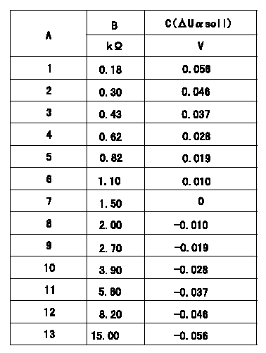
Compensation resistance/compensation voltage comparison
A = Compensation resistor number
B= Compensation resistance
C = Compensation voltage delta U alpha soll
----------
----------
----------
----------
0000001601 HARNESS & CONNECTOR
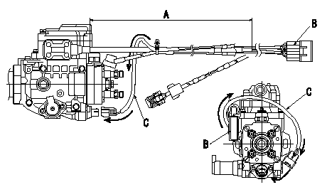
T.C.V. connector assembly specification
(1)Ensure the GE cable is not twisted at section A.
(2)Refer to diagram for direction of connector B.
(3)Route the TCV harnes C in the direction indicated by the arrows in the figure and install the connector.
----------
----------
----------
----------
0000001701 HARNESS & CONNECTOR
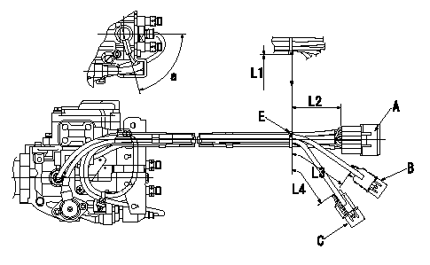
Harness position specification
(1)Where the connector side's harness is pulled out, position the protective tube at the connector side so that lead wire exposure is the minimum.
(2)Fix the harness using clips to the dimensions shown in the figure.
(3)Cut the binder leaving no more than L1 excess.
A = GE, TCV, Q adjustment
B=NP,FCV
C=TPS
E = binder
----------
----------
a=(75deg) L1=Max.2mm L2=110+-10mm L3=80+-10mm L4=70+-10mm
----------
----------
a=(75deg) L1=Max.2mm L2=110+-10mm L3=80+-10mm L4=70+-10mm
0000001801 HARNESS & CONNECTOR
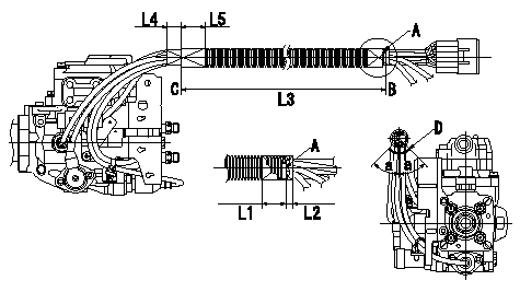
Corrugated tube assembly specification
(1)Where the pump sensor side and connector side harness come out, attach protective tube to the sensor side and the connector side (except for the FCV grommet position) so that the lead wires are not exposed or visible.
(2)Align the end of the corrugated tube with clip A and fix it using black vinyl tape (L1, L2).
(3)Confirm that the dimension to the end of the corrugated tube C is L3, and fix it using black vinyl tape (L4, L5).
(4)Refer to the illustration for the position of the corrugated tube slit.
A = binder
B = outside edge of binder
C = end of corrugated tube
D = position of corrugated tube's slit
----------
----------
L1=Max.25mm L2=Max.10mm L3=325+-10mm L4=(20mm) L5=(30mm) a=45deg
----------
----------
L1=Max.25mm L2=Max.10mm L3=325+-10mm L4=(20mm) L5=(30mm) a=45deg
0000001901 HARNESS & CONNECTOR
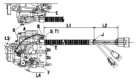
Harness fixing specification
(1)At the clip position J at dimension L2 from the rear end of the connector, and the dimension L1 from the metal end of the clip B, fix using the socket head bolt and the spring washer.
(2)Adjust the length of dimension L1 within the tolerance so that the TPS and Np harness at A is not excessively loose, then fix using the clip.
(3)Clip the GE cable and the FCV harness using clip E, the GE cable and the FCV-TCV harness using clip F, and the TPS-NP harness using clip G.
B = clip
D = socket head bolt
E = binder
F = binder
G=Binder
J = clip position
----------
----------
L1=300+-10mm L2=(110mm) L3=27~37mm L4=5~15mm T1=9.8~13.7N-m(1.0~1.4kgf-m)
----------
----------
L1=300+-10mm L2=(110mm) L3=27~37mm L4=5~15mm T1=9.8~13.7N-m(1.0~1.4kgf-m)
0000002001 HARNESS & CONNECTOR
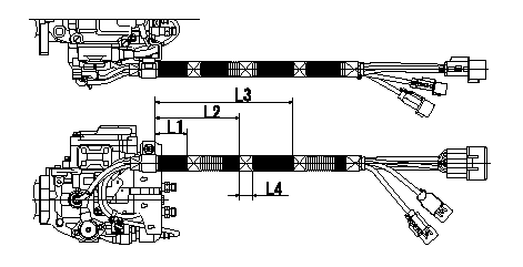
Vinyl tape assembly specification
Wrap with black vinyl tape (at 3 positions) from the end of the clip's metal portion at the positions shown in the figure (dimensions indicated).
----------
----------
L1=55+-10mm L2=125+-10mm L3=195+-10mm L4=(20mm)
----------
----------
L1=55+-10mm L2=125+-10mm L3=195+-10mm L4=(20mm)
0000002101 HARNESS & CONNECTOR
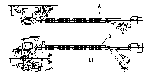
Marking application specification
(1)Ensure the corrugated tube is not twisted and then mark the position A shown in the figure.
(2)3) Mark at the two locations indicated in the figure ( viewed from the side of the pump and the top of the pump). The markings must be the dimensions shown and approx. 5 mm wide.
(3)2) Use indelible paint for steel.
A = white marking
B = End of tape binding
----------
----------
L1=20+-5mm
----------
----------
L1=20+-5mm
Information:
Table 2
Specifications for Valve Opening Pressure
Nozzle Assembly Valve Opening Pressure
1W-5829
10300 to 17690 kPa (1500 to 2505 psi)
4W-1819
4W-8483
7E-3969
7N-0449
7W-3710
7W-8043
9N-3979
101-0060
115-3354
122-9007
9L-7883
16560 to 17990 kPa (2400 to 2600 psi)
9L-9263
9N-2366
9L-6969
13090 to 19900 kPa (1900 2900 psi)
9N-3299
9N-3700 If the fuel nozzle is not within specifications, stop the test and do not use the nozzle.Check for Tip Leakage
Close the gauge protector valve (0 to 40,000 kPa (0 to 5,800 psi) gauge).
Flush the fuel nozzle that is being tested by pumping the tester for 3 full strokes.
Open the gauge protector valve (0 to 40,000 kPa (0 to 5,800 psi) gauge).
Use a clean cloth to dry the tip and the body of the fuel injector. All test fluid should be wiped from the nozzle assembly.
A clean cloth should be wrapped around the top of the fuel nozzle in order to absorb any internal return leakage.
Calculate the test pressure that will be used for the tip leakage test.Use the fuel nozzle's valve opening pressure, that has been previously recorded, in order to calculate the test pressure for the nozzle that is being tested.
Subtract a value of 1875 kPa (275 psi) from the valve opening pressure that was previously obtained.
Record the result of the calculation as the test pressure that will be used for the tip leakage test.
Slowly apply the test pressure, that has been calculated in Step 6, to the fuel nozzle.
Close the pump isolator valve.
Hold this test pressure for 10 seconds.
Count the number of drops of test fluid that drips from the nozzle during the duration of the test. Open the pump isolator valve in order to release the pressure on the fuel nozzle when the test is completed.Refer to the information that is provided in Table 3 in order to evaluate the results of the test.Note: Ensure that any test fluid that collects on the tip of the fuel nozzle is not fluid leakage from the test fixture.
Table 3
Specifications for Tip Leakage
(Leakage within 15 seconds after the test pressure is applied to the nozzle.)
Nozzle Assembly Maximum Leakage
1W-5829 20 drops (1)
4W-1819
4W-8483
7E-3969
7N-0449
7W-3710
7W-8043
9N-3979
101-0060
115-3354
122-9007
9L-7883 3 drops (1)
9L-9263
9N-2366
9L-6969 30 drops (1)
9N-3299
9N-3700
( 1 ) No minimum specificationIf the tip leakage for the fuel nozzle is not within specifications, stop the test and do not use the fuel nozzle.Test the Fuel Nozzle for Plugged Orifices
Illustration 2 g00923165
Spray patterns for pencil type fuel nozzles.
Close the gauge protector valve (0 to 40,000 kPa (0 to 5,800 psi) gauge).
Rapidly increase the pressure on the fuel nozzle until fluid sprays from the tip of the fuel nozzle.Note: For this test, each full
