Information injection-pump assembly
BOSCH
9 460 614 122
9460614122
ZEXEL
104700-9100
1047009100
Rating:
Compare Prices: .
As an associate, we earn commssions on qualifying purchases through the links below
Components :
| 0. | INJECTION-PUMP ASSEMBLY | 104700-9100 |
| 1. | _ | |
| 2. | FUEL INJECTION PUMP | 104600-9100 |
| 3. | NUMBER PLATE | 148643-1600 |
| 4. | _ | |
| 5. | CAPSULE | |
| 6. | ADJUSTING DEVICE | |
| 7. | NOZZLE AND HOLDER ASSY | |
| 8. | Nozzle and Holder | |
| 9. | Open Pre:MPa(Kqf/cm2) | |
| 10. | NOZZLE-HOLDER | |
| 11. | NOZZLE |
Scheme ###:
| 1/6. | [1] | 146601-0700 | PACKING RING |
| 6. | [1] | 146100-0120 | SUPPLY PUMP |
| 9. | [1] | 148103-0400 | COVER |
| 10. | [2] | 139104-0000 | FLAT-HEAD SCREW |
| 12. | [1] | 148200-0520 | DRIVE SHAFT |
| 17. | [1] | 146204-0000 | PLAIN WASHER |
| 20. | [1] | 148210-0120 | ROLLER SET |
| 24. | [1] | 146303-0000 | BEARING PIN |
| 25. | [1] | 146304-0000 | BEARING PIN |
| 26. | [1] | 146305-0000 | CLAMPING BAND |
| 27. | [1] | 146205-0000 | SLOTTED WASHER |
| 29. | [1] | 146220-4320 | CAM PLATE |
| 30. | [1] | 146600-0800 | O-RING |
| 31. | [1] | 146300-1900 | PUMP PLUNGER |
| 32. | [1] | 146301-0000 | SLIDING PIECE |
| 33. | [1] | 146603-1100 | SHIM |
| 34. | [1] | 146306-1800 | COMPRESSION SPRING |
| 34B. | [1] | 146306-2100 | COMPRESSION SPRING |
| 35/1. | [0] | 146603-0700 | SHIM D17.5&7.5T0.60 |
| 35/1. | [0] | 146603-0800 | SHIM D17.5&7.5T0.70 |
| 35/1. | [0] | 146603-0900 | SHIM D17.5&7.5T0.90 |
| 35/1. | [0] | 146603-1000 | SHIM D17.5&7.5T1.00 |
| 35/1. | [0] | 146603-1100 | SHIM D17.5&7.5T1.20 |
| 35/1. | [0] | 146603-3600 | SHIM D17.5&7.5T2.40 |
| 36. | [1] | 146600-0800 | O-RING |
| 37. | [1] | 479766-1420 | TIMER PISTON SENSOR |
| 38. | [2] | 146622-1200 | HEX-SOCKET-HEAD CAP SCREW |
| 39. | [1] | 146310-5600 | COVER |
| 40. | [2] | 146622-1300 | BLEEDER SCREW |
| 43. | [1] | 146230-0000 | SHIM |
| 44. | [1] | 146230-0100 | PLAIN WASHER |
| 45. | [1] | 146231-0001 | SLOTTED WASHER |
| 47. | [2] | 146233-0000 | SLOTTED WASHER |
| 48/1. | [1] | 146603-0000 | SHIM D17.0&5.2T0.50 |
| 48/1. | [1] | 146603-0100 | SHIM D17.0&5.2T0.80 |
| 48/1. | [1] | 146603-0200 | SHIM D17.0&5.2T1.00 |
| 48/1. | [1] | 146603-0300 | SHIM D17.0&5.2T1.20 |
| 48/1. | [1] | 146603-0400 | SHIM D17.0&5.2T1.50 |
| 48/1. | [1] | 146603-0500 | SHIM D17.0&5.2T1.80 |
| 48/1. | [1] | 146603-0600 | SHIM D17.0&5.2T2.00 |
| 48/1. | [1] | 146690-1400 | SHIM D17&5.2T0.9 |
| 48/1. | [1] | 146690-1500 | SHIM D17&5.2T1.1 |
| 48/1. | [1] | 146690-1600 | SHIM D17&5.2T1.3 |
| 48/1. | [1] | 146690-1700 | SHIM D17&5.2T1.4 |
| 48/1. | [1] | 146690-1800 | SHIM D17&5.2T1.6 |
| 48/1. | [1] | 146690-1900 | SHIM D17&5.2T1.7 |
| 48/1. | [1] | 146690-5800 | SHIM D17&5.2T2.1 |
| 48/1. | [1] | 146690-5900 | SHIM D17&5.2T2.2 |
| 48/1. | [1] | 146690-6000 | SHIM D17&5.2T2.3 |
| 48/1. | [1] | 146690-6100 | SHIM D17&5.2T2.4 |
| 48/1. | [1] | 146690-6200 | SHIM D17&5.2T2.5 |
| 48/1. | [1] | 146690-6300 | SHIM D17&5.2T2.6 |
| 48/1. | [1] | 146690-6400 | SHIM D17&5.2T2.7 |
| 48/1. | [1] | 146690-6500 | SHIM D17&5.2T2.8 |
| 48/1. | [1] | 146690-6600 | SHIM D17&5.2T2.9 |
| 48/1. | [1] | 146690-6700 | SHIM D17&5.2T3.0 |
| 48/1. | [1] | 146690-6800 | SHIM D17&5.2T3.1 |
| 48/1. | [1] | 146690-6900 | SHIM D17&5.2T3.2 |
| 48/1. | [1] | 146690-7000 | SHIM D17&5.2T3.3 |
| 48/1. | [1] | 146690-7100 | SHIM D17&5.2T3.4 |
| 48/1. | [1] | 146690-7200 | SHIM D17&5.2T0.4 |
| 48/1. | [1] | 146690-7300 | SHIM D17&5.2T0.6 |
| 48/1. | [1] | 146690-7400 | SHIM D17&5.2T0.7 |
| 48/1. | [1] | 146690-7500 | SHIM D17&5.2T1.9 |
| 48/1. | [1] | 146690-7800 | SHIM D17&5.2T0.2 |
| 49. | [2] | 146234-0600 | GUIDE PIN |
| 50. | [1] | 146403-8720 | HYDRAULIC HEAD |
| 50. | [1] | 146403-8720 | HYDRAULIC HEAD |
| 50. | [1] | 146403-8720 | HYDRAULIC HEAD |
| 51. | [1] | 146600-0000 | O-RING |
| 52/1. | [1] | 146420-0000 | SHIM D9.5&3.0T1.90 |
| 52/1. | [1] | 146420-0100 | SHIM D9.5&3.0T1.92 |
| 52/1. | [1] | 146420-0200 | SHIM D9.5&3.0T1.94 |
| 52/1. | [1] | 146420-0300 | SHIM D9.5&3.0T1.96 |
| 52/1. | [1] | 146420-0400 | SHIM D9.5&3.0T1.98 |
| 52/1. | [1] | 146420-0500 | SHIM D9.5&3.0T2.00 |
| 52/1. | [1] | 146420-0600 | SHIM D9.5&3.0T2.02 |
| 52/1. | [1] | 146420-0700 | SHIM D9.5&3.0T2.04 |
| 52/1. | [1] | 146420-0800 | SHIM D9.5&3.0T2.06 |
| 52/1. | [1] | 146420-0900 | SHIM D9.5&3.0T2.08 |
| 52/1. | [1] | 146420-1000 | SHIM D9.5&3.0T2.10 |
| 52/1. | [1] | 146420-1100 | SHIM D9.5&3.0T2.12 |
| 52/1. | [1] | 146420-1200 | SHIM D9.5&3.0T2.14 |
| 52/1. | [1] | 146420-1300 | SHIM D9.5&3.0T2.16 |
| 52/1. | [1] | 146420-1400 | SHIM D9.5&3.0T2.18 |
| 52/1. | [1] | 146420-1500 | SHIM D9.5&3.0T2.20 |
| 52/1. | [1] | 146420-1600 | SHIM D9.5&3.0T2.22 |
| 52/1. | [1] | 146420-1700 | SHIM D9.5&3.0T2.24 |
| 52/1. | [1] | 146420-1800 | SHIM D9.5&3.0T2.26 |
| 52/1. | [1] | 146420-1900 | SHIM D9.5&3.0T2.28 |
| 52/1. | [1] | 146420-2000 | SHIM D9.5&3.0T2.30 |
| 52/1. | [1] | 146420-2100 | SHIM D9.5&3.0T2.32 |
| 52/1. | [1] | 146420-2200 | SHIM D9.5&3.0T2.34 |
| 52/1. | [1] | 146420-2300 | SHIM D9.5&3.0T2.36 |
| 52/1. | [1] | 146420-2400 | SHIM D9.5&3.0T2.38 |
| 52/1. | [1] | 146420-2500 | SHIM D9.5&3.0T2.40 |
| 52/1. | [1] | 146420-2600 | SHIM D9.5&3.0T2.42 |
| 52/1. | [1] | 146420-2700 | SHIM D9.5&3.0T2.44 |
| 52/1. | [1] | 146420-2800 | SHIM D9.5&3.0T2.46 |
| 52/1. | [1] | 146420-2900 | SHIM D9.5&3.0T2.48 |
| 52/1. | [1] | 146420-3000 | SHIM D9.5&3.0T2.50 |
| 52/1. | [1] | 146420-3100 | SHIM D9.5&3.0T2.52 |
| 52/1. | [1] | 146420-3200 | SHIM D9.5&3.0T2.54 |
| 52/1. | [1] | 146420-3300 | SHIM D9.5&3.0T2.56 |
| 52/1. | [1] | 146420-3400 | SHIM D9.5&3.0T2.58 |
| 52/1. | [1] | 146420-3500 | SHIM D9.5&3.0T2.60 |
| 52/1. | [1] | 146420-3600 | SHIM D9.5&3.0T2.62 |
| 52/1. | [1] | 146420-3700 | SHIM D9.5&3.0T2.64 |
| 52/1. | [1] | 146420-3800 | SHIM D9.5&3.0T2.66 |
| 52/1. | [1] | 146420-3900 | SHIM D9.5&3.0T2.68 |
| 52/1. | [1] | 146420-4000 | SHIM D9.5&3.0T2.70 |
| 52/1. | [1] | 146420-4100 | SHIM D9.5&3.0T2.72 |
| 52/1. | [1] | 146420-4200 | SHIM D9.5&3.0T2.74 |
| 52/1. | [1] | 146420-4300 | SHIM D9.5&3.0T2.76 |
| 52/1. | [1] | 146420-4400 | SHIM D9.5&3.0T2.78 |
| 52/1. | [1] | 146420-4500 | SHIM D9.5&3.0T2.80 |
| 52/1. | [1] | 146420-4600 | SHIM D9.5&3.0T2.82 |
| 52/1. | [1] | 146420-4700 | SHIM D9.5&3.0T2.84 |
| 52/1. | [1] | 146420-4800 | SHIM D9.5&3.0T2.86 |
| 52/1. | [1] | 146420-4900 | SHIM D9.5&3.0T2.88 |
| 52/1. | [1] | 146420-5000 | SHIM D9.5&3.0T2.90 |
| 52/1. | [1] | 146420-5100 | SHIM D9.5&3.0T1.74 |
| 52/1. | [1] | 146420-5200 | SHIM D9.5&3.0T1.76 |
| 52/1. | [1] | 146420-5300 | SHIM D9.5&3.0T1.78 |
| 52/1. | [1] | 146420-5400 | SHIM D9.5&3.0T1.80 |
| 52/1. | [1] | 146420-5500 | SHIM D9.5&3.0T1.82 |
| 52/1. | [1] | 146420-5600 | SHIM D9.5&3.0T1.84 |
| 52/1. | [1] | 146420-5700 | SHIM D9.5&3.0T1.86 |
| 52/1. | [1] | 146420-5800 | SHIM D9.5&3.0T1.88 |
| 54. | [4] | 146433-0100 | GASKET |
| 55. | [4] | 146430-0320 | DELIVERY-VALVE ASSEMBLY VE4 |
| 56. | [4] | 146432-0801 | COMPRESSION SPRING |
| 58. | [4] | 146440-3120 | FITTING |
| 60. | [3] | 146622-1800 | FLAT-HEAD SCREW |
| 123. | [1] | 146622-0900 | FLAT-HEAD SCREW |
| 130. | [1] | 146421-1920 | CAPSULE |
| 130/2. | [1] | 139508-0200 | GASKET |
| 130/3. | [1] | 146422-0700 | BLEEDER SCREW |
| 130/4. | [1] | 146600-0500 | O-RING |
| 133. | [1] | 146600-0600 | O-RING |
| 134. | [1] | 146600-0700 | O-RING |
| 135. | [1] | 146110-3520 | CONTROL VALVE |
| 135/5. | [1] | 146114-0000 | SPRING WASHER |
| 136. | [1] | 148120-0320 | OVER FLOW VALVE |
| 137. | [3] | 139512-0500 | GASKET |
| 138. | [1] | 146669-5821 | INLET UNION |
| 158. | [1] | 146663-5500 | SPACER BUSHING |
| 200. | [1] | 146206-0100 | COILED SPRING |
| 205. | [1] | 029470-4030 | WOODRUFF KEY |
| 230. | [1] | 148613-6620 | BRACKET |
| 236. | [1] | 146622-1400 | HEX-SOCKET-HEAD CAP SCREW |
| 237. | [1] | 146622-1500 | HEX-SOCKET-HEAD CAP SCREW |
| 240. | [1] | 146688-3720 | PULLING ELECTROMAGNET |
| 240/8. | [1] | 146600-1700 | O-RING |
| 243. | [1] | 146621-1000 | UNION NUT |
| 245. | [3] | 139512-0500 | GASKET |
| 246. | [1] | 146125-1000 | EYE BOLT |
| 247. | [1] | 146669-6821 | INLET UNION |
| 248. | [1] | 146663-5600 | SPACER BUSHING |
| 275. | [1] | 148612-1600 | BRACKET |
| 276. | [2] | 146622-1700 | BLEEDER SCREW |
| 278. | [2] | 146663-5700 | SPACER BUSHING |
| 282. | [1] | 146622-1900 | BLEEDER SCREW |
| 504/1. | [1] | 146649-4500 | RESISTER NO. 1 0.18K:OHM |
| 504/1. | [1] | 146649-4600 | RESISTER NO. 2 0.30K:OHM |
| 504/1. | [1] | 146649-4700 | RESISTER NO. 3 0.43K:OHM |
| 504/1. | [1] | 146649-4800 | RESISTER NO. 4 0.62K:OHM |
| 504/1. | [1] | 146649-4900 | RESISTER NO. 5 0.82K:OHM |
| 504/1. | [1] | 146649-5000 | RESISTER NO. 6 1.10K:OHM |
| 504/1. | [1] | 146649-5100 | RESISTER NO. 7 1.50K:OHM |
| 504/1. | [1] | 146649-5200 | RESISTER NO. 8 2.00K:OHM |
| 504/1. | [1] | 146649-5300 | RESISTER NO. 9 2.70K:OHM |
| 504/1. | [1] | 146649-5400 | RESISTER NO.10 3.90K:OHM |
| 504/1. | [1] | 146649-5500 | RESISTER NO.11 5.60K:OHM |
| 504/1. | [1] | 146649-5600 | RESISTER NO.12 8.20K:OHM |
| 504/1. | [1] | 146649-5700 | RESISTER NO.13 15.00K:OHM |
| 505. | [1] | 148530-4120 | GOVERNOR;ELECTRIC |
| 506. | [3] | 146622-1000 | FLAT-HEAD SCREW |
| 515. | [1] | 106144-1071 | TIMING CONTROL VALVE |
| 515/7. | [1] | 161440-3800 | O-RING |
| 515/8. | [1] | 161440-3700 | O-RING |
| 516. | [2] | 146622-1600 | HEX-SOCKET-HEAD CAP SCREW |
| 530. | [3] | 148650-0000 | BINDER |
| 531. | [1] | 479766-1120 | PULSE GENERATOR |
| 531/6. | [1] | 479773-6500 | O-RING |
| 535. | [1] | 148650-0300 | TAPE 1500MM |
| 536. | [1] | 148650-3300 | TUBE |
| 538. | [2] | 148650-3400 | BINDER |
| 551. | [1] | 146659-9500 | CLAMPING BAND |
| 552. | [1] | 014110-8442 | LOCKING WASHER |
| 553. | [1] | 010208-1242 | HEX-SOCKET-HEAD CAP SCREW |
| 800S. | [1] | 148009-0620 | PUMP HOUSING |
| 800S/1/6. | [1] | 146601-0700 | PACKING RING |
| 804S. | [1] | 146232-0720 | COMPRESSION SPRING |
| 810S. | [1] | 146600-4620 | REPAIR SET |
| 821S. | [1] | 146210-5720 | ROLLER SET |
| 878S. | [1] | 148600-1300 | SEAL RING |
| 906. | [1] | 148643-1600 | NAMEPLATE |
Include in #2:
104700-9100
as INJECTION-PUMP ASSEMBLY
Cross reference number
BOSCH
9 460 614 122
9460614122
ZEXEL
104700-9100
1047009100
Zexel num
Bosch num
Firm num
Name
104700-9100
9 460 614 122
INJECTION-PUMP ASSEMBLY
4D56TCI 11CL INJECTION PUMP ASSY COVEC 4 COVEC
4D56TCI 11CL INJECTION PUMP ASSY COVEC 4 COVEC
104700-9100
9 460 614 122
3310542700 HYUNDAI
INJECTION-PUMP ASSEMBLY
4D56TCI K 11CL INJECTION PUMP ASSY COVEC 4 COVEC
4D56TCI K 11CL INJECTION PUMP ASSY COVEC 4 COVEC
Calibration Data:
Adjustment conditions
Test oil
1404 Test oil ISO4113orSAEJ967d
1404 Test oil ISO4113orSAEJ967d
Test oil temperature
degC
45
45
50
Nozzle
105780-0060
Bosch type code
NP-DN0SD1510
Nozzle holder
105780-2150
Opening pressure
MPa
13
13
13.3
Opening pressure
kgf/cm2
133
133
136
Injection pipe
157805-7320
Injection pipe
Inside diameter - outside diameter - length (mm) mm 2-6-450
Inside diameter - outside diameter - length (mm) mm 2-6-450
Joint assembly
157641-4720
Tube assembly
157641-4020
Transfer pump pressure
kPa
20
20
20
Transfer pump pressure
kgf/cm2
0.2
0.2
0.2
Direction of rotation (viewed from drive side)
Right R
Right R
Governor adjustment
Pump speed
r/min
1000
1000
1000
TCV duty (%) F TCV 60Hz
%
100
100
100
U alpha soll
V
2.7
2.7
2.7
Pump chamber pressure
kPa
598
569
627
Pump chamber pressure
kgf/cm2
6.1
5.8
6.4
Basic
*
Governor adjustment_02
Pump speed
r/min
100
100
100
TCV duty (%) F TCV 60Hz
%
100
100
100
U alpha soll
V
2.7
2.7
2.7
Pump chamber pressure
kPa
294
294
Pump chamber pressure
kgf/cm2
3
3
Governor adjustment_03
Pump speed
r/min
1000
1000
1000
TCV duty (%) F TCV 60Hz
%
100
100
100
U alpha soll
V
2.7
2.7
2.7
Pump chamber pressure
kPa
598
559
637
Pump chamber pressure
kgf/cm2
6.1
5.7
6.5
Governor adjustment_04
Pump speed
r/min
2000
2000
2000
TCV duty (%) F TCV 60Hz
%
100
100
100
U alpha soll
V
2.7
2.7
2.7
Pump chamber pressure
kPa
735
686
784
Pump chamber pressure
kgf/cm2
7.5
7
8
Boost compensator adjustment
Pump speed
r/min
1000
1000
1000
TCV duty (%) F TCV 60Hz
%
100
100
100
U alpha soll
V
2.7
2.7
2.7
Timer stroke
mm
7.7
7.5
7.9
Basic
*
Boost compensator adjustment_02
Pump speed
r/min
100
100
100
TCV duty (%) F TCV 60Hz
%
100
100
100
U alpha soll
V
2.7
2.7
2.7
Timer stroke
mm
1.8
0.3
3.3
Boost compensator adjustment_03
Pump speed
r/min
350
350
350
TCV duty (%) F TCV 60Hz
%
100
100
100
U alpha soll
V
2.7
2.7
2.7
Timer stroke
mm
5.2
3.1
7.3
Boost compensator adjustment_04
Pump speed
r/min
1000
1000
1000
TCV duty (%) F TCV 60Hz
%
100
100
100
U alpha soll
V
2.7
2.7
2.7
Timer stroke
mm
7.7
7.4
8
Boost compensator adjustment_05
Pump speed
r/min
1000
1000
1000
TCV duty (%) F TCV 60Hz
%
70
70
70
U alpha soll
V
2.7
2.7
2.7
Timer stroke
mm
4
1.9
6.1
Boost compensator adjustment_06
Pump speed
r/min
2000
2000
2000
TCV duty (%) F TCV 60Hz
%
100
100
100
U alpha soll
V
2.7
2.7
2.7
Timer stroke
mm
9.75
9.3
10.2
Boost compensator adjustment_07
Pump speed
r/min
2000
2000
2000
TCV duty (%) F TCV 60Hz
%
0
0
0
U alpha soll
V
2.7
2.7
2.7
Timer stroke
mm
0
0
0
Timer adjustment
Pump speed
r/min
1000
1000
1000
TCV duty (%) F TCV 60Hz
%
0
0
0
U alpha soll
V
2.7
2.7
2.7
Vtps
V
0.51
0.382
0.638
Basic
*
Timer adjustment_02
Pump speed
r/min
1000
1000
1000
TCV duty (%) F TCV 60Hz
%
0
0
0
U alpha soll
V
2.7
2.7
2.7
Vtps
V
0.51
0.382
0.638
Timer adjustment_03
Pump speed
r/min
1000
1000
1000
TCV duty (%) F TCV 60Hz
%
100
100
100
U alpha soll
V
2.7
2.7
2.7
Vtps
V
1.925
1.702
2.148
Speed control lever angle
Pump speed
r/min
1000
1000
1000
TCV duty (%) F TCV 60Hz
%
100
100
100
U alpha soll
V
2.7
2.7
2.7
Overflow quantity
cm3/min
550
420
680
0000000901
Pump speed
r/min
1250
1250
1250
U alpha soll + dU alpha soll
V
2.83
2.83
2.83
TCV duty (%) F TCV 60Hz
%
100
100
100
Average injection quantity
mm3/st.
68.8
68.3
69.3
Difference in delivery
mm3/st.
3.5
Basic
*
_02
Pump speed
r/min
375
375
375
U alpha soll + dU alpha soll
V
1.9
1.9
1.9
TCV duty (%) F TCV 60Hz
%
100
100
100
Average injection quantity
mm3/st.
12.8
9.8
15.8
Difference in delivery
mm3/st.
2.5
Basic
*
Remarks
Confirmation of difference in delivery
Confirmation of difference in delivery
_03
Pump speed
r/min
2575
2575
2575
U alpha soll + dU alpha soll
V
1.8
1.8
1.8
TCV duty (%) F TCV 60Hz
%
100
100
100
Average injection quantity
mm3/st.
18.3
15.8
20.8
Difference in delivery
mm3/st.
5.5
Basic
*
Remarks
Confirmation of difference in delivery
Confirmation of difference in delivery
_04
Pump speed
r/min
100
100
100
U alpha soll + dU alpha soll
V
2.9
2.9
2.9
TCV duty (%) F TCV 60Hz
%
100
100
100
Average injection quantity
mm3/st.
51.4
41.4
61.4
_05
Pump speed
r/min
375
375
375
U alpha soll + dU alpha soll
V
1.9
1.9
1.9
TCV duty (%) F TCV 60Hz
%
100
100
100
Average injection quantity
mm3/st.
12.8
9.8
15.8
_06
Pump speed
r/min
500
500
500
U alpha soll + dU alpha soll
V
2.46
2.46
2.46
TCV duty (%) F TCV 60Hz
%
100
100
100
Average injection quantity
mm3/st.
45.6
43.1
48.1
_07
Pump speed
r/min
750
750
750
U alpha soll + dU alpha soll
V
2.68
2.68
2.68
TCV duty (%) F TCV 60Hz
%
100
100
100
Average injection quantity
mm3/st.
60.1
57.6
62.6
_08
Pump speed
r/min
1000
1000
1000
U alpha soll + dU alpha soll
V
2.84
2.84
2.84
TCV duty (%) F TCV 60Hz
%
100
100
100
Average injection quantity
mm3/st.
70.7
68.2
73.2
_09
Pump speed
r/min
1250
1250
1250
U alpha soll + dU alpha soll
V
2.83
2.83
2.83
TCV duty (%) F TCV 60Hz
%
100
100
100
Average injection quantity
mm3/st.
68.8
67.8
69.8
_10
Pump speed
r/min
1500
1500
1500
U alpha soll + dU alpha soll
V
2.78
2.78
2.78
TCV duty (%) F TCV 60Hz
%
100
100
100
Average injection quantity
mm3/st.
66.5
64
69
_11
Pump speed
r/min
1750
1750
1750
U alpha soll + dU alpha soll
V
2.72
2.72
2.72
TCV duty (%) F TCV 60Hz
%
100
100
100
Average injection quantity
mm3/st.
61.7
59.2
64.2
_12
Pump speed
r/min
2000
2000
2000
U alpha soll + dU alpha soll
V
2.66
2.66
2.66
TCV duty (%) F TCV 60Hz
%
100
100
100
Average injection quantity
mm3/st.
59
56.5
61.5
_13
Pump speed
r/min
2575
2575
2575
U alpha soll + dU alpha soll
V
1.8
1.8
1.8
TCV duty (%) F TCV 60Hz
%
100
100
100
Average injection quantity
mm3/st.
18.3
15.8
20.8
_14
Pump speed
r/min
2575
2575
2575
U alpha soll + dU alpha soll
V
1
1
1
TCV duty (%) F TCV 60Hz
%
100
100
100
Average injection quantity
mm3/st.
3
Stop lever angle
Pump speed
r/min
2000
2000
2000
U alpha soll + dU alpha soll
V
2.66
2.66
2.66
TCV duty (%) F TCV 60Hz
%
100
100
100
Average injection quantity
cm3/min
0
0
0
0000001101
Pump speed
r/min
200
200
200
TCV duty (%) F TCV 60Hz
%
100
100
100
U alpha soll
V
2.7
2.7
2.7
Speed output
N=Measure the actual speed. r/min N+-8
N=Measure the actual speed. r/min N+-8
0000001201
Pump speed
r/min
1250
1250
1250
TCV duty (%) F TCV 60Hz
%
100
100
100
U alpha soll
V
2.73
2.73
2.73
Temperature output
Measure T = actual output temperature degC T+-5
Measure T = actual output temperature degC T+-5
0000001301
Max. applied voltage
V
8
8
8
Test voltage
V
13
12
14
0000001401
K dimension
mm
3.3
3.2
3.4
KF dimension
mm
5.9
5.8
6
Pre-stroke
mm
0.1
0.08
0.12
Test data Ex:
Injection timing adjustment Comp. resistor/voltage
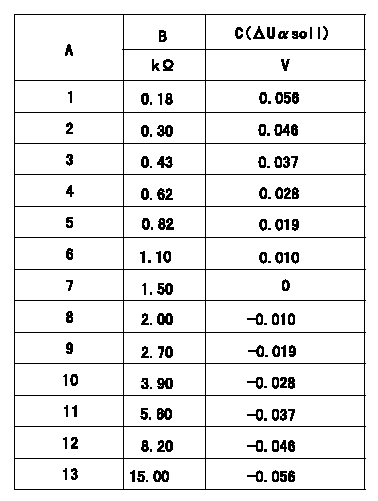
Compensation resistance/compensation voltage comparison
A = Compensation resistor number
B= Compensation resistance
C = Compensation voltage delta U alpha soll
----------
----------
----------
----------
0000001601 HARNESS & CONNECTOR
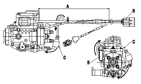
T.C.V. connector assembly specification
(1)Ensure the GE cable is not twisted at section A.
(2)Refer to diagram for direction of connector B.
(3)Route the TCV harnes C in the direction indicated by the arrows in the figure and install the connector.
----------
----------
----------
----------
0000001701 HARNESS & CONNECTOR
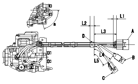
Harness position specification
(1)Where each pump sensor side harness comes out, attach protective tube to the sensor side (except for the FCV grommet position) so that the lead wires are not exposed or visible.
(2)Make the GE cable's protective tube L1.
(3)Fix the harness using black vinyl tape to the dimensions shown in the figure.
A = GE, TCV, Q adjustment
B=NP,FCV
C=TPS
D = black vinyl tape
----------
----------
a=(75deg) L1=Max.15mm L2=(20mm) L3=110+-10mm L4=80+-10mm L5=70+-10mm
----------
----------
a=(75deg) L1=Max.15mm L2=(20mm) L3=110+-10mm L4=80+-10mm L5=70+-10mm
0000001801 HARNESS & CONNECTOR
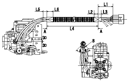
Corrugated tube assembly specification
(1)Make the end of the corrugated tube L1 and wrap it in black vinyl tape (L2, L3) to fix it.
(2)Confirm that the corrugated tube dimension is L4, wrap it in black vinyl tape (L5, L6) and fix it.
(3)Refer to the illustration for the position of the corrugated tube slit.
A = end of corrugated tube
B = position of corrugated tube's slit
----------
----------
L1=135+-10mm L2=(30mm) L3=(25mm) L4=450+-10mm L5=(20mm) L6=(30mm) a=45deg
----------
----------
L1=135+-10mm L2=(30mm) L3=(25mm) L4=450+-10mm L5=(20mm) L6=(30mm) a=45deg
0000001901 HARNESS & CONNECTOR
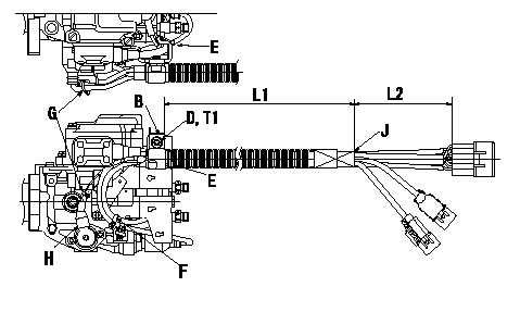
Harness fixing specification
(1)At the tape position J at dimension L2 from the rear end of the connector, and the dimension L1 from the metal end of the clip B, fix using the socket head bolt and the spring washer.
(2)Clip the GE cable and the FCV harness using clip E, the GE cable and the FCV-TCV harness using clip F, and the TPS-NP harness using clip G.
(3)Attach the binder G after ensuring that the TPS cover H is not loose.
B = clip
D = socket head bolt
E = binder
F = binder
G=Binder
H = TPS cover
J = tape position
----------
----------
L1=450+-10mm L2=110mm T1=9.8~13.7N-m(1.0~1.4kgf-m)
----------
----------
L1=450+-10mm L2=110mm T1=9.8~13.7N-m(1.0~1.4kgf-m)
0000002001 HARNESS & CONNECTOR
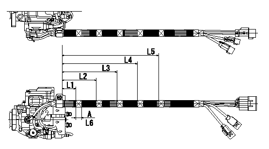
Vinyl tape assembly specification
Wrap with black vinyl tape (at 5 positions) from the end of the clip's metal portion at the positions shown in the figure (dimensions indicated).
A = black vinyl tape
----------
----------
L1=55+-10mm L2=130+-10mm L3=205+-10mm L4=280+-10mm L5=340+-10mm L6=(20mm)
----------
----------
L1=55+-10mm L2=130+-10mm L3=205+-10mm L4=280+-10mm L5=340+-10mm L6=(20mm)
0000002101 HARNESS & CONNECTOR
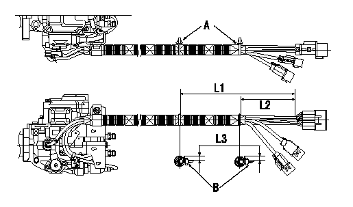
Binder union specification
(1)Attach binder.
(2)Be careful of B's orientation.
(3)Cut off excess binder
----------
----------
L1=267.5+-10mm L2=127.5+-10mm L3=Max.10mm
----------
----------
L1=267.5+-10mm L2=127.5+-10mm L3=Max.10mm
0000002201 HARNESS & CONNECTOR
Vinyl tape assembly specification 2.
Wrap each connector's lead wires where they leave the connector with black vinyl tape.
After completing all of the procedures, ensure no lead wires are exposed after routing the harness.
----------
----------
----------
----------
Information:
Repeat Steps 4 through 6 to remove (bleed) air from the rear table lift cylinder (not shown).
Open (CCW) hand pump control knob (11) to completely lower the DPF cleaner table. Close (CW) the hand pump control knob.
Illustration 38 g02728258
(28) Hydraulic Oil Level 51 to 102 mm (2.0 to 4.0 inch)
Check the oil level in the pump reservoir. Remove fill cap (13) located on the end cap of the hand pump. Hydraulic oil level (28) should be 51 to 102 mm (2.0 to 4.0 inch) from the bottom of the fill hole. Add high-grade hydraulic oil, if needed.Note: A clean wire tie can be used as a dipstick to measure the hydraulic oil level in the pump reservoir.Troubleshooting Guide
Table 3
Symptom Solution
Air dryer desiccant is a pinkish color. 1. Replace or regenerate the desiccant. Refer to ""Maintenance Section"".
Bursting does not occur. 1. Check display screen for error message.
2. Check power connection to burst valve solenoid.
Cabinet doors do not close correctly. 1. Look for damaged door hinges, seals, and latches.
2. Verify that vehicle sensors have been removed from DPF.
Cabinet doors open during burst process. 1. Verify that doors are correctly latched.
2. Look for damage to door latches.
3. Check seals between DPF and adapters.
Clamping force cannot be obtained. 1. Look for hydraulic fluid leaks.
2. Check fluid level in hydraulic pump. Refer to ""Maintenance Section"".
Clamping force does not hold. 1. Upon initial clamping, it is possible for clamp load to drop
689 to 1379 kPa (99.9 to 200.0 psi) within the first minute, due to temperature effects. After reclamping, the drop should be virtually zero.
2. Look for hydraulic fluid leaks.
Display screen is blank. 1. Verify that machine is ON, plugged into an outlet, and power is available to the outlet.
2. Reset circuit breakers located on left side of control cabinet.
DPF does not line up correctly on the table. 1. Verify that correct adapters are being used.
2. Verify DPF is correctly seated on to lower adapter.
DPF is damaged after cleaning process. 1. Check DPFs for damage before cleaning.
2. Look for damage on adapters.
3. Verify that correct cleaning protocol was entered into machine.
DPF is not cleaned. 1. Check orientation of DPF. Refer to ""General Information"" Section.
2. Verify that correct cleaning protocol was entered into machine.
3. Look for other DPF conditions that may prevent successful cleaning.
Have questions with 104700-9100?
Group cross 104700-9100 ZEXEL
104700-9100
9 460 614 122
INJECTION-PUMP ASSEMBLY
4D56TCI
4D56TCI
Hyundai
104700-9100
9 460 614 122
3310542700
INJECTION-PUMP ASSEMBLY
4D56TCI
4D56TCI

