Information injection-pump assembly
BOSCH
9 460 614 206
9460614206
ZEXEL
104700-0552
1047000552
MAZDA
WLE713800B
wle713800b
Rating:
Compare Prices: .
As an associate, we earn commssions on qualifying purchases through the links below

£1,649.24
18 Oct 2018
22.05[9.90] pounds
Robert Bos: Robert Bosch GMbH.
Bosch 9460614206 Injection Pump Assembly
Components :
| 0. | INJECTION-PUMP ASSEMBLY | 104700-0552 |
| 1. | _ | |
| 2. | FUEL INJECTION PUMP | 104600-0552 |
| 3. | NUMBER PLATE | 148638-0700 |
| 4. | _ | |
| 5. | CAPSULE | |
| 6. | ADJUSTING DEVICE | |
| 7. | NOZZLE AND HOLDER ASSY | 105148-1183 |
| 8. | Nozzle and Holder | PN4013H50C |
| 9. | Open Pre:MPa(Kqf/cm2) | 10.8(110) |
| 10. | NOZZLE-HOLDER | 105078-0111 |
| 11. | NOZZLE | 105007-1210 |
Scheme ###:
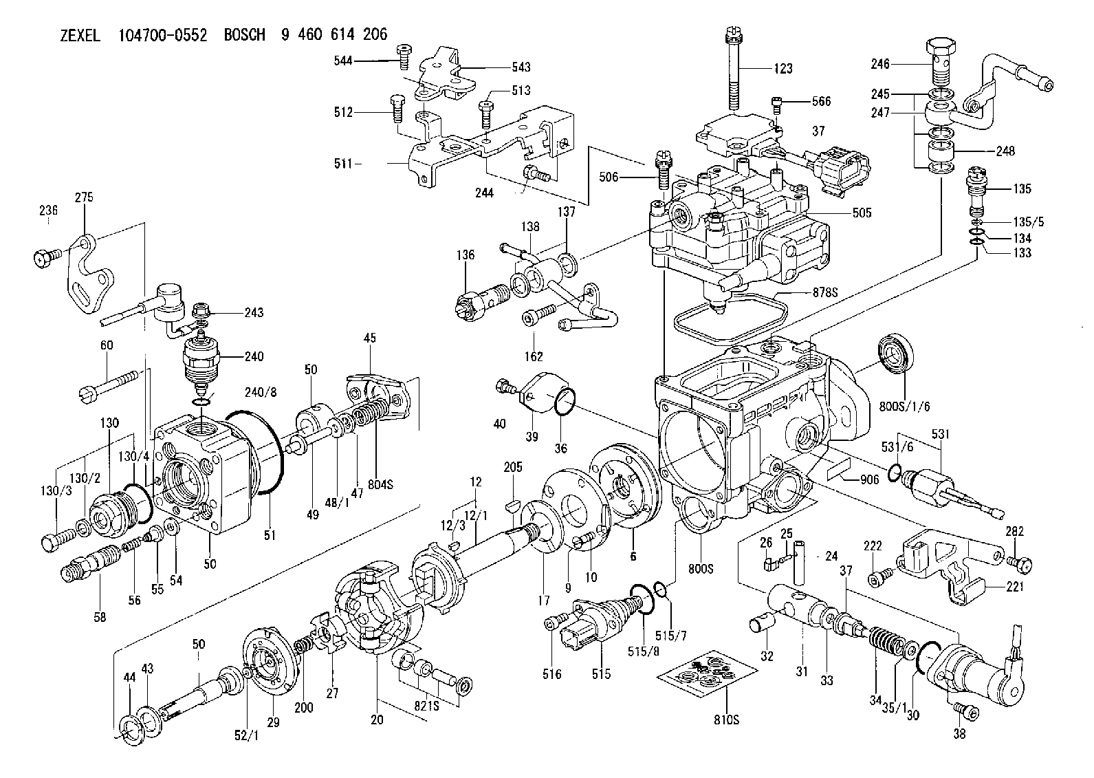
| 1/6. | [1] | 146601-0700 | PACKING RING |
| 6. | [1] | 146100-0120 | SUPPLY PUMP |
| 9. | [1] | 148103-0500 | COVER |
| 10. | [2] | 139104-0000 | FLAT-HEAD SCREW |
| 12. | [1] | 148200-1020 | DRIVE SHAFT |
| 12/1. | [1] | 148200-0400 | DRIVE SHAFT |
| 12/3. | [1] | 146201-0000 | WOODRUFF KEY |
| 17. | [1] | 146204-0000 | PLAIN WASHER |
| 20. | [1] | 148210-0620 | ROLLER SET |
| 24. | [1] | 146303-0100 | BEARING PIN |
| 25. | [1] | 146304-0000 | BEARING PIN |
| 26. | [1] | 146305-0000 | CLAMPING BAND |
| 27. | [1] | 146205-0200 | SLOTTED WASHER |
| 29. | [1] | 146220-4720 | CAM PLATE |
| 30. | [1] | 146600-0800 | O-RING |
| 31. | [1] | 146300-5600 | PUMP PLUNGER |
| 32. | [1] | 146301-0000 | SLIDING PIECE |
| 33. | [1] | 146603-0700 | SHIM D17.5&7.5T0.60 |
| 34. | [1] | 146306-2100 | COMPRESSION SPRING |
| 35/1. | [0] | 146603-0700 | SHIM D17.5&7.5T0.60 |
| 35/1. | [0] | 146603-0800 | SHIM D17.5&7.5T0.70 |
| 35/1. | [0] | 146603-0900 | SHIM D17.5&7.5T0.90 |
| 35/1. | [0] | 146603-1000 | SHIM D17.5&7.5T1.00 |
| 35/1. | [0] | 146603-1100 | SHIM D17.5&7.5T1.20 |
| 35/1. | [0] | 146603-3600 | SHIM D17.5&7.5T2.40 |
| 36. | [1] | 146600-0800 | O-RING |
| 37. | [1] | 479778-7421 | TIMER PISTON SENSOR |
| 37. | [1] | 479778-7421 | TIMER PISTON SENSOR |
| 38. | [2] | 010206-2040 | HEX-SOCKET-HEAD CAP SCREW |
| 39. | [1] | 146310-0100 | COVER |
| 40. | [2] | 146620-5000 | BLEEDER SCREW |
| 43. | [1] | 146230-0000 | SHIM |
| 44. | [1] | 146230-0100 | PLAIN WASHER |
| 45. | [1] | 146231-0001 | SLOTTED WASHER |
| 47. | [2] | 146233-0000 | SLOTTED WASHER |
| 48/1. | [1] | 146603-0000 | SHIM D17.0&5.2T0.50 |
| 48/1. | [1] | 146603-0100 | SHIM D17.0&5.2T0.80 |
| 48/1. | [1] | 146603-0200 | SHIM D17.0&5.2T1.00 |
| 48/1. | [1] | 146603-0300 | SHIM D17.0&5.2T1.20 |
| 48/1. | [1] | 146603-0400 | SHIM D17.0&5.2T1.50 |
| 48/1. | [1] | 146603-0500 | SHIM D17.0&5.2T1.80 |
| 48/1. | [1] | 146603-0600 | SHIM D17.0&5.2T2.00 |
| 48/1. | [1] | 146690-1400 | SHIM D17&5.2T0.9 |
| 48/1. | [1] | 146690-1500 | SHIM D17&5.2T1.1 |
| 48/1. | [1] | 146690-1600 | SHIM D17&5.2T1.3 |
| 48/1. | [1] | 146690-1700 | SHIM D17&5.2T1.4 |
| 48/1. | [1] | 146690-1800 | SHIM D17&5.2T1.6 |
| 48/1. | [1] | 146690-1900 | SHIM D17&5.2T1.7 |
| 48/1. | [1] | 146690-5800 | SHIM D17&5.2T2.1 |
| 48/1. | [1] | 146690-5900 | SHIM D17&5.2T2.2 |
| 48/1. | [1] | 146690-6000 | SHIM D17&5.2T2.3 |
| 48/1. | [1] | 146690-6100 | SHIM D17&5.2T2.4 |
| 48/1. | [1] | 146690-6200 | SHIM D17&5.2T2.5 |
| 48/1. | [1] | 146690-6300 | SHIM D17&5.2T2.6 |
| 48/1. | [1] | 146690-6400 | SHIM D17&5.2T2.7 |
| 48/1. | [1] | 146690-6500 | SHIM D17&5.2T2.8 |
| 48/1. | [1] | 146690-6600 | SHIM D17&5.2T2.9 |
| 48/1. | [1] | 146690-6700 | SHIM D17&5.2T3.0 |
| 48/1. | [1] | 146690-6800 | SHIM D17&5.2T3.1 |
| 48/1. | [1] | 146690-6900 | SHIM D17&5.2T3.2 |
| 48/1. | [1] | 146690-7000 | SHIM D17&5.2T3.3 |
| 48/1. | [1] | 146690-7100 | SHIM D17&5.2T3.4 |
| 48/1. | [1] | 146690-7200 | SHIM D17&5.2T0.4 |
| 48/1. | [1] | 146690-7300 | SHIM D17&5.2T0.6 |
| 48/1. | [1] | 146690-7400 | SHIM D17&5.2T0.7 |
| 48/1. | [1] | 146690-7500 | SHIM D17&5.2T1.9 |
| 48/1. | [1] | 146690-7800 | SHIM D17&5.2T0.2 |
| 49. | [2] | 146234-0600 | GUIDE PIN |
| 50. | [1] | 146403-9221 | HYDRAULIC HEAD |
| 50. | [1] | 146403-9221 | HYDRAULIC HEAD |
| 50. | [1] | 146403-9221 | HYDRAULIC HEAD |
| 51. | [1] | 146600-0000 | O-RING |
| 52/1. | [1] | 146420-0000 | SHIM D9.5&3.0T1.90 |
| 52/1. | [1] | 146420-0100 | SHIM D9.5&3.0T1.92 |
| 52/1. | [1] | 146420-0200 | SHIM D9.5&3.0T1.94 |
| 52/1. | [1] | 146420-0300 | SHIM D9.5&3.0T1.96 |
| 52/1. | [1] | 146420-0400 | SHIM D9.5&3.0T1.98 |
| 52/1. | [1] | 146420-0500 | SHIM D9.5&3.0T2.00 |
| 52/1. | [1] | 146420-0600 | SHIM D9.5&3.0T2.02 |
| 52/1. | [1] | 146420-0700 | SHIM D9.5&3.0T2.04 |
| 52/1. | [1] | 146420-0800 | SHIM D9.5&3.0T2.06 |
| 52/1. | [1] | 146420-0900 | SHIM D9.5&3.0T2.08 |
| 52/1. | [1] | 146420-1000 | SHIM D9.5&3.0T2.10 |
| 52/1. | [1] | 146420-1100 | SHIM D9.5&3.0T2.12 |
| 52/1. | [1] | 146420-1200 | SHIM D9.5&3.0T2.14 |
| 52/1. | [1] | 146420-1300 | SHIM D9.5&3.0T2.16 |
| 52/1. | [1] | 146420-1400 | SHIM D9.5&3.0T2.18 |
| 52/1. | [1] | 146420-1500 | SHIM D9.5&3.0T2.20 |
| 52/1. | [1] | 146420-1600 | SHIM D9.5&3.0T2.22 |
| 52/1. | [1] | 146420-1700 | SHIM D9.5&3.0T2.24 |
| 52/1. | [1] | 146420-1800 | SHIM D9.5&3.0T2.26 |
| 52/1. | [1] | 146420-1900 | SHIM D9.5&3.0T2.28 |
| 52/1. | [1] | 146420-2000 | SHIM D9.5&3.0T2.30 |
| 52/1. | [1] | 146420-2100 | SHIM D9.5&3.0T2.32 |
| 52/1. | [1] | 146420-2200 | SHIM D9.5&3.0T2.34 |
| 52/1. | [1] | 146420-2300 | SHIM D9.5&3.0T2.36 |
| 52/1. | [1] | 146420-2400 | SHIM D9.5&3.0T2.38 |
| 52/1. | [1] | 146420-2500 | SHIM D9.5&3.0T2.40 |
| 52/1. | [1] | 146420-2600 | SHIM D9.5&3.0T2.42 |
| 52/1. | [1] | 146420-2700 | SHIM D9.5&3.0T2.44 |
| 52/1. | [1] | 146420-2800 | SHIM D9.5&3.0T2.46 |
| 52/1. | [1] | 146420-2900 | SHIM D9.5&3.0T2.48 |
| 52/1. | [1] | 146420-3000 | SHIM D9.5&3.0T2.50 |
| 52/1. | [1] | 146420-3100 | SHIM D9.5&3.0T2.52 |
| 52/1. | [1] | 146420-3200 | SHIM D9.5&3.0T2.54 |
| 52/1. | [1] | 146420-3300 | SHIM D9.5&3.0T2.56 |
| 52/1. | [1] | 146420-3400 | SHIM D9.5&3.0T2.58 |
| 52/1. | [1] | 146420-3500 | SHIM D9.5&3.0T2.60 |
| 52/1. | [1] | 146420-3600 | SHIM D9.5&3.0T2.62 |
| 52/1. | [1] | 146420-3700 | SHIM D9.5&3.0T2.64 |
| 52/1. | [1] | 146420-3800 | SHIM D9.5&3.0T2.66 |
| 52/1. | [1] | 146420-3900 | SHIM D9.5&3.0T2.68 |
| 52/1. | [1] | 146420-4000 | SHIM D9.5&3.0T2.70 |
| 52/1. | [1] | 146420-4100 | SHIM D9.5&3.0T2.72 |
| 52/1. | [1] | 146420-4200 | SHIM D9.5&3.0T2.74 |
| 52/1. | [1] | 146420-4300 | SHIM D9.5&3.0T2.76 |
| 52/1. | [1] | 146420-4400 | SHIM D9.5&3.0T2.78 |
| 52/1. | [1] | 146420-4500 | SHIM D9.5&3.0T2.80 |
| 52/1. | [1] | 146420-4600 | SHIM D9.5&3.0T2.82 |
| 52/1. | [1] | 146420-4700 | SHIM D9.5&3.0T2.84 |
| 52/1. | [1] | 146420-4800 | SHIM D9.5&3.0T2.86 |
| 52/1. | [1] | 146420-4900 | SHIM D9.5&3.0T2.88 |
| 52/1. | [1] | 146420-5000 | SHIM D9.5&3.0T2.90 |
| 52/1. | [1] | 146420-5100 | SHIM D9.5&3.0T1.74 |
| 52/1. | [1] | 146420-5200 | SHIM D9.5&3.0T1.76 |
| 52/1. | [1] | 146420-5300 | SHIM D9.5&3.0T1.78 |
| 52/1. | [1] | 146420-5400 | SHIM D9.5&3.0T1.80 |
| 52/1. | [1] | 146420-5500 | SHIM D9.5&3.0T1.82 |
| 52/1. | [1] | 146420-5600 | SHIM D9.5&3.0T1.84 |
| 52/1. | [1] | 146420-5700 | SHIM D9.5&3.0T1.86 |
| 52/1. | [1] | 146420-5800 | SHIM D9.5&3.0T1.88 |
| 54. | [4] | 146433-0100 | GASKET D12&6.4T1.00 |
| 55. | [4] | 146430-0320 | DELIVERY-VALVE ASSEMBLY |
| 56. | [4] | 146432-0000 | COMPRESSION SPRING |
| 58. | [4] | 146440-0220 | FITTING |
| 60. | [4] | 139106-0100 | FLAT-HEAD SCREW |
| 123. | [1] | 146620-8800 | FLAT-HEAD SCREW |
| 130. | [1] | 146421-1320 | CAPSULE |
| 130/2. | [1] | 026508-1140 | GASKET D11.4&8.2T1 |
| 130/3. | [1] | 146422-0700 | BLEEDER SCREW |
| 130/4. | [1] | 146600-0500 | O-RING |
| 133. | [1] | 146600-0600 | O-RING |
| 134. | [1] | 146600-0700 | O-RING |
| 135. | [1] | 146110-3220 | CONTROL VALVE |
| 135/5. | [1] | 146114-0000 | SPRING WASHER |
| 136. | [1] | 148120-0020 | OVER FLOW VALVE |
| 137. | [2] | 139512-0500 | GASKET |
| 138. | [1] | 146677-3720 | INLET UNION |
| 162. | [1] | 010206-1040 | HEX-SOCKET-HEAD CAP SCREW |
| 200. | [1] | 146206-0100 | COILED SPRING |
| 205. | [1] | 146201-0100 | WOODRUFF KEY |
| 221. | [1] | 148613-5200 | BRACKET |
| 222. | [1] | 146620-2700 | HEX-SOCKET-HEAD CAP SCREW |
| 236. | [2] | 139006-4800 | BLEEDER SCREW |
| 240. | [1] | 146650-4320 | PULLING ELECTROMAGNET |
| 240/8. | [1] | 146600-1700 | O-RING |
| 243. | [1] | 146621-4901 | UNION NUT |
| 244. | [1] | 139006-5700 | BLEEDER SCREW |
| 245. | [3] | 139512-0500 | GASKET |
| 246. | [1] | 146125-0700 | EYE BOLT |
| 247. | [1] | 146677-1320 | INLET UNION |
| 248. | [1] | 146614-0200 | SPACER BUSHING |
| 275. | [1] | 148612-1500 | BRACKET |
| 282. | [1] | 139006-4400 | BLEEDER SCREW |
| 505. | [1] | 148531-3020 | GOVERNOR;ELECTRIC |
| 506. | [3] | 146620-8900 | FLAT-HEAD SCREW |
| 511. | [1] | 148613-7320 | BRACKET |
| 512. | [1] | 010006-0870 | BLEEDER SCREW M6P1L8 7T |
| 513. | [2] | 139006-4400 | BLEEDER SCREW |
| 515. | [1] | 106144-1071 | TIMING CONTROL VALVE |
| 515/7. | [1] | 161440-3800 | O-RING |
| 515/8. | [1] | 161440-3700 | O-RING |
| 516. | [2] | 010206-1440 | HEX-SOCKET-HEAD CAP SCREW M6P1L14 |
| 531. | [1] | 479774-7620 | PULSE GENERATOR |
| 531/6. | [1] | 479773-6500 | O-RING |
| 543. | [1] | 148613-7400 | BRACKET |
| 544. | [2] | 139006-4400 | BLEEDER SCREW |
| 566. | [4] | 010234-1040 | HEX-SOCKET-HEAD CAP SCREW |
| 800S. | [1] | 148009-0820 | PUMP HOUSING |
| 800S/1/6. | [1] | 146601-0700 | PACKING RING |
| 804S. | [1] | 146232-1520 | COMPRESSION SPRING |
| 810S. | [1] | 146600-5120 | REPAIR SET |
| 821S. | [1] | 146210-5820 | ROLLER SET |
| 878S. | [1] | 148600-1300 | SEAL RING |
| 906. | [1] | 148638-0400 | NAMEPLATE |
Include in #2:
104700-0552
as INJECTION-PUMP ASSEMBLY
Cross reference number
BOSCH
9 460 614 206
9460614206
ZEXEL
104700-0552
1047000552
MAZDA
WLE713800B
wle713800b
Zexel num
Bosch num
Firm num
Name
104700-0552
9 460 614 206
WLE713800B MAZDA
INJECTION-PUMP ASSEMBLY
WL K 11CL INJECTION PUMP ASSY COVEC 4 COVEC
WL K 11CL INJECTION PUMP ASSY COVEC 4 COVEC
Calibration Data:
Adjustment conditions
Test oil
ISO4113
Nozzle
105780-0060
Bosch type code
NP-DN0SD1510
Nozzle holder
105780-2150
Opening pressure
MPa
13
13
13.3
Opening pressure
kgf/cm2
133
133
136
Injection pipe
157805-7320
Injection pipe
Inside diameter - outside diameter - length (mm) mm 2-6-450
Inside diameter - outside diameter - length (mm) mm 2-6-450
Joint assembly
157641-4720
Tube assembly
157641-4020
Transfer pump pressure
kPa
20
20
20
Transfer pump pressure
kgf/cm2
0.2
0.2
0.2
Direction of rotation (viewed from drive side)
Left L
Left L
Manual controller assembly
157966-4020
ECU assembly
157966-3920
Manual controller main harness
157966-4920
Manual controller intermediate harness
157966-5820
ROM harness
157966-5020
0000000201
K dimension
mm
3.3
3.2
3.4
KF dimension
mm
6.01
5.91
6.11
Pre-stroke
mm
0.03
0.01
0.05
Injection quantity adjustment
Max. applied voltage
V
8
8
8
Test voltage
V
13
12
14
Information:
Introduction
The following procedures contain crucial information on correctly installing the new 162-2501 Hose As and the 258-8917 Protection Sleeve .Note: The 162-2501 Hose As replaces 107-7942 Tube As .Installation Procedure of the Hose Assembly
Illustration 1 g01230674
Remove old 162-2501 Hose As (1). Keep all of the manifold and pump fittings attached.Note: Step 2 is only for 3408E engines.
Remove the 7W-6492 Pipe Plug (2) from the aftercooler housing (3). Install the 8T-6762 Pipe Plug into the aftercooler housing.
Illustration 2 g01230678
Note: Always tighten the fittings with your hand before you use a wrench. Support the hose and the elbow while you tighten in order to avoid the following damage: twisting, kinking and side loading.
Loosen elbow (4) and jam nut (5) .
Hand tighten the nut on the hose (5) to the elbow (4) .
Install the other end of the hose (6) to the pump fitting. Tighten the nut to 125 15 N m (90 11 lb ft).
Hold the elbow (4) in position and torque the jam nut to 145 15 N m (105 11 lb ft).
Support the elbow (4). Tighten the nut (5) on the hose to 125 15 N m (90 11 lb ft).
Illustration 3 g01230687
Illustration 3 shows the routing of the 162-2501 Hose As (8). The hose is routed from the rail, around the rear of the fuel transfer pump (9), and into the 90 degree fitting (7) that is installed into the pump.
Illustration 4 g01230689
Some 3408 engines use an aftercooler that is mounted high. The mounting bracket (10) is located close to the 162-2501 Hose As (8). If there is not enough clearance to install the protective sleeve, the hose will need to be loosened and the hose will need to be repositioned. Refer to 5 for repositioning of the hose.
Illustration 5 g01230690
The hose must be realigned if any of the following conditions exist:
Not enough clearance against the fuel transfer pump
Not enough clearance against the support bracket
Loosen the end of the hose (12) .
Loosen the elbow and the jam nut (11). Note: Do not remove the hose.
Reposition the hose in order to acquire the desired clearance.
Hold the end of the hose (12). Tighten the jam nut (11) .Tighten the jam nut to the following torque. ... 143 15 N m (105 11 lb ft)Note: Locking pliers can be used on the crimped portion of the hose. Do not use the locking pliers on the braided portion of the hose. This will damage the hose which will cause a failure.
Tighten the end of the hose (12) .Tighten the end of the hose to the following torque. ... 125 15 N m (92 11 lb ft)Note: If adjustment of the hose is required, make sure that the hose is not bent. Also, ensure that the hose is not twisted. If these conditions exist the PTFE liner can be damaged.Installation of the Protective Sleeve Over the New Hose Assembly
Illustration 6 g01106118
Top viewInstallation of a protective sleeve for the hoses of the
Have questions with 104700-0552?
Group cross 104700-0552 ZEXEL
Mazda
Mazda
Mitsubishi
Mazda
104700-0552
9 460 614 206
WLE713800B
INJECTION-PUMP ASSEMBLY
WL
WL