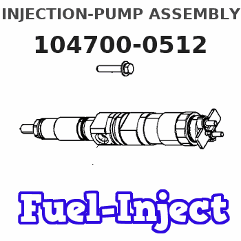
Information injection-pump assembly
BOSCH
9 460 613 193
9460613193
ZEXEL
104700-0512
1047000512
MAZDA
RF1G13800D
rf1g13800d
Rating:
Components :
| 0. | INJECTION-PUMP ASSEMBLY | 104700-0512 |
| 1. | _ | |
| 2. | FUEL INJECTION PUMP | 104600-0512 |
| 3. | NUMBER PLATE | 148636-1100 |
| 4. | _ | |
| 5. | CAPSULE | |
| 6. | ADJUSTING DEVICE | |
| 7. | NOZZLE AND HOLDER ASSY | 105148-1531 |
| 8. | Nozzle and Holder | RF1G 13 H50B |
| 9. | Open Pre:MPa(Kqf/cm2) | 14.7{150} |
| 10. | NOZZLE-HOLDER | 105078-0111 |
| 11. | NOZZLE | 105007-1370 |
Scheme ###:
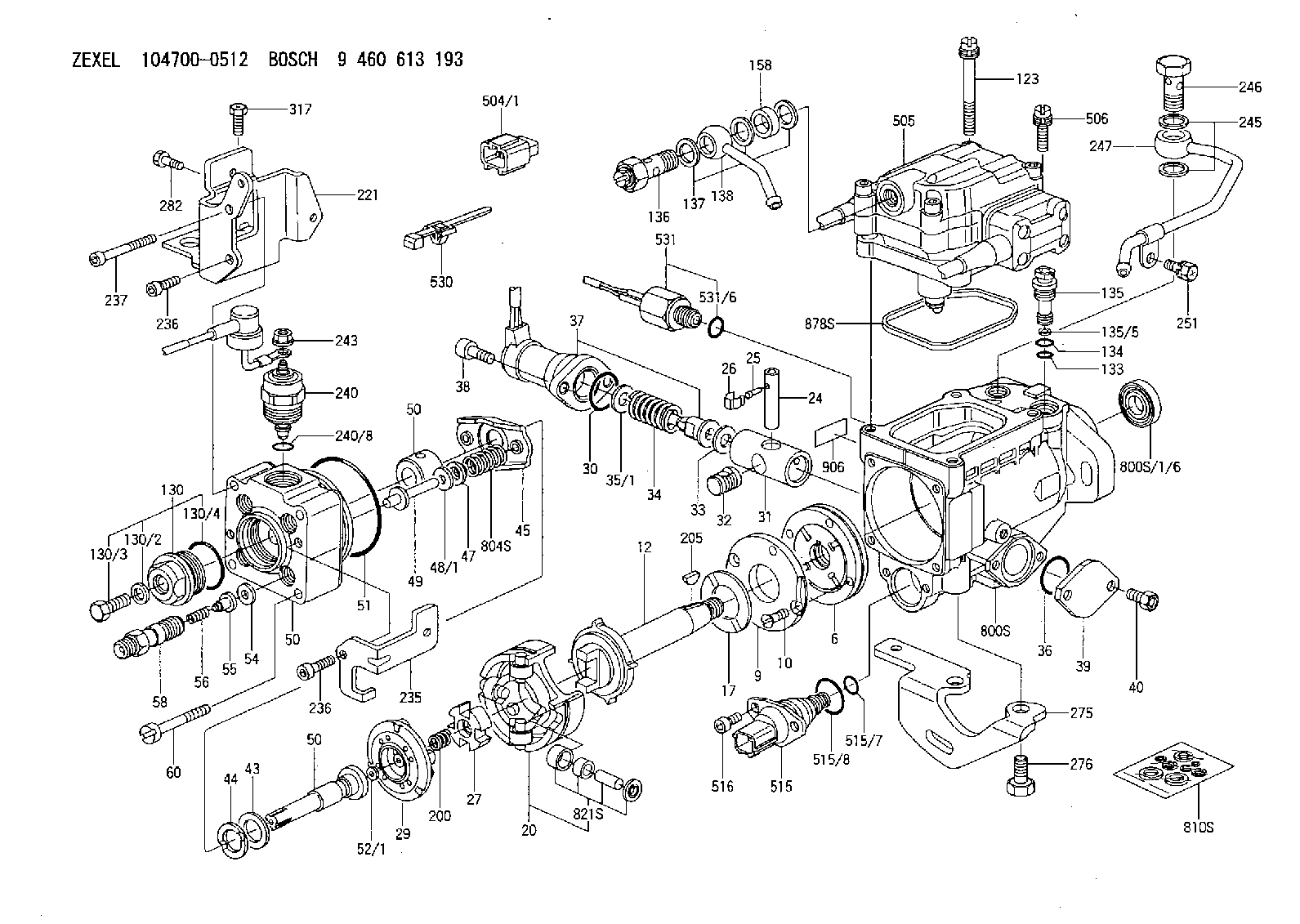
| 1/6. | [1] | 146601-0700 | PACKING RING |
| 6. | [1] | 146100-0120 | SUPPLY PUMP |
| 9. | [1] | 148103-0400 | COVER |
| 10. | [2] | 139104-0000 | FLAT-HEAD SCREW |
| 12. | [1] | 148200-0920 | DRIVE SHAFT |
| 17. | [1] | 146204-0000 | PLAIN WASHER |
| 20. | [1] | 148210-0420 | ROLLER SET |
| 24. | [1] | 146303-0100 | BEARING PIN |
| 25. | [1] | 146304-0000 | BEARING PIN |
| 26. | [1] | 146305-0000 | CLAMPING BAND |
| 27. | [1] | 146205-0000 | SLOTTED WASHER |
| 29. | [1] | 146220-4820 | CAM PLATE |
| 30. | [1] | 146600-0800 | O-RING |
| 31. | [1] | 146300-1900 | PUMP PLUNGER |
| 32. | [1] | 146301-0000 | SLIDING PIECE |
| 33. | [1] | 146603-0700 | SHIM |
| 34. | [1] | 146306-2100 | COMPRESSION SPRING |
| 35/1. | [0] | 146603-0700 | SHIM D17.5&7.5T0.60 |
| 35/1. | [0] | 146603-0800 | SHIM D17.5&7.5T0.70 |
| 35/1. | [0] | 146603-0900 | SHIM D17.5&7.5T0.90 |
| 35/1. | [0] | 146603-1000 | SHIM D17.5&7.5T1.00 |
| 35/1. | [0] | 146603-1100 | SHIM D17.5&7.5T1.20 |
| 35/1. | [0] | 146603-3600 | SHIM D17.5&7.5T2.40 |
| 36. | [1] | 146600-0800 | O-RING |
| 37. | [1] | 479765-1320 | TIMER PISTON SENSOR |
| 38. | [2] | 010206-2040 | HEX-SOCKET-HEAD CAP SCREW |
| 39. | [1] | 146310-0100 | COVER |
| 40. | [2] | 146620-5000 | BLEEDER SCREW |
| 43. | [1] | 146230-0000 | SHIM |
| 44. | [1] | 146230-0100 | PLAIN WASHER |
| 45. | [1] | 146231-0001 | SLOTTED WASHER |
| 47. | [2] | 146233-0000 | SLOTTED WASHER |
| 48/1. | [1] | 146603-0000 | SHIM D17.0&5.2T0.50 |
| 48/1. | [1] | 146603-0100 | SHIM D17.0&5.2T0.80 |
| 48/1. | [1] | 146603-0200 | SHIM D17.0&5.2T1.00 |
| 48/1. | [1] | 146603-0300 | SHIM D17.0&5.2T1.20 |
| 48/1. | [1] | 146603-0400 | SHIM D17.0&5.2T1.50 |
| 48/1. | [1] | 146603-0500 | SHIM D17.0&5.2T1.80 |
| 48/1. | [1] | 146603-0600 | SHIM D17.0&5.2T2.00 |
| 48/1. | [1] | 146690-1400 | SHIM D17&5.2T0.9 |
| 48/1. | [1] | 146690-1500 | SHIM D17&5.2T1.1 |
| 48/1. | [1] | 146690-1600 | SHIM D17&5.2T1.3 |
| 48/1. | [1] | 146690-1700 | SHIM D17&5.2T1.4 |
| 48/1. | [1] | 146690-1800 | SHIM D17&5.2T1.6 |
| 48/1. | [1] | 146690-1900 | SHIM D17&5.2T1.7 |
| 48/1. | [1] | 146690-5800 | SHIM D17&5.2T2.1 |
| 48/1. | [1] | 146690-5900 | SHIM D17&5.2T2.2 |
| 48/1. | [1] | 146690-6000 | SHIM D17&5.2T2.3 |
| 48/1. | [1] | 146690-6100 | SHIM D17&5.2T2.4 |
| 48/1. | [1] | 146690-6200 | SHIM D17&5.2T2.5 |
| 48/1. | [1] | 146690-6300 | SHIM D17&5.2T2.6 |
| 48/1. | [1] | 146690-6400 | SHIM D17&5.2T2.7 |
| 48/1. | [1] | 146690-6500 | SHIM D17&5.2T2.8 |
| 48/1. | [1] | 146690-6600 | SHIM D17&5.2T2.9 |
| 48/1. | [1] | 146690-6700 | SHIM D17&5.2T3.0 |
| 48/1. | [1] | 146690-6800 | SHIM D17&5.2T3.1 |
| 48/1. | [1] | 146690-6900 | SHIM D17&5.2T3.2 |
| 48/1. | [1] | 146690-7000 | SHIM D17&5.2T3.3 |
| 48/1. | [1] | 146690-7100 | SHIM D17&5.2T3.4 |
| 48/1. | [1] | 146690-7200 | SHIM D17&5.2T0.4 |
| 48/1. | [1] | 146690-7300 | SHIM D17&5.2T0.6 |
| 48/1. | [1] | 146690-7400 | SHIM D17&5.2T0.7 |
| 48/1. | [1] | 146690-7500 | SHIM D17&5.2T1.9 |
| 48/1. | [1] | 146690-7800 | SHIM D17&5.2T0.2 |
| 49. | [2] | 146234-0600 | GUIDE PIN |
| 50. | [1] | 146403-8220 | HYDRAULIC HEAD |
| 50. | [1] | 146403-8220 | HYDRAULIC HEAD |
| 50. | [1] | 146403-8220 | HYDRAULIC HEAD |
| 51. | [1] | 146600-0000 | O-RING |
| 52/1. | [1] | 146420-0000 | SHIM D9.5&3.0T1.90 |
| 52/1. | [1] | 146420-0100 | SHIM D9.5&3.0T1.92 |
| 52/1. | [1] | 146420-0200 | SHIM D9.5&3.0T1.94 |
| 52/1. | [1] | 146420-0300 | SHIM D9.5&3.0T1.96 |
| 52/1. | [1] | 146420-0400 | SHIM D9.5&3.0T1.98 |
| 52/1. | [1] | 146420-0500 | SHIM D9.5&3.0T2.00 |
| 52/1. | [1] | 146420-0600 | SHIM D9.5&3.0T2.02 |
| 52/1. | [1] | 146420-0700 | SHIM D9.5&3.0T2.04 |
| 52/1. | [1] | 146420-0800 | SHIM D9.5&3.0T2.06 |
| 52/1. | [1] | 146420-0900 | SHIM D9.5&3.0T2.08 |
| 52/1. | [1] | 146420-1000 | SHIM D9.5&3.0T2.10 |
| 52/1. | [1] | 146420-1100 | SHIM D9.5&3.0T2.12 |
| 52/1. | [1] | 146420-1200 | SHIM D9.5&3.0T2.14 |
| 52/1. | [1] | 146420-1300 | SHIM D9.5&3.0T2.16 |
| 52/1. | [1] | 146420-1400 | SHIM D9.5&3.0T2.18 |
| 52/1. | [1] | 146420-1500 | SHIM D9.5&3.0T2.20 |
| 52/1. | [1] | 146420-1600 | SHIM D9.5&3.0T2.22 |
| 52/1. | [1] | 146420-1700 | SHIM D9.5&3.0T2.24 |
| 52/1. | [1] | 146420-1800 | SHIM D9.5&3.0T2.26 |
| 52/1. | [1] | 146420-1900 | SHIM D9.5&3.0T2.28 |
| 52/1. | [1] | 146420-2000 | SHIM D9.5&3.0T2.30 |
| 52/1. | [1] | 146420-2100 | SHIM D9.5&3.0T2.32 |
| 52/1. | [1] | 146420-2200 | SHIM D9.5&3.0T2.34 |
| 52/1. | [1] | 146420-2300 | SHIM D9.5&3.0T2.36 |
| 52/1. | [1] | 146420-2400 | SHIM D9.5&3.0T2.38 |
| 52/1. | [1] | 146420-2500 | SHIM D9.5&3.0T2.40 |
| 52/1. | [1] | 146420-2600 | SHIM D9.5&3.0T2.42 |
| 52/1. | [1] | 146420-2700 | SHIM D9.5&3.0T2.44 |
| 52/1. | [1] | 146420-2800 | SHIM D9.5&3.0T2.46 |
| 52/1. | [1] | 146420-2900 | SHIM D9.5&3.0T2.48 |
| 52/1. | [1] | 146420-3000 | SHIM D9.5&3.0T2.50 |
| 52/1. | [1] | 146420-3100 | SHIM D9.5&3.0T2.52 |
| 52/1. | [1] | 146420-3200 | SHIM D9.5&3.0T2.54 |
| 52/1. | [1] | 146420-3300 | SHIM D9.5&3.0T2.56 |
| 52/1. | [1] | 146420-3400 | SHIM D9.5&3.0T2.58 |
| 52/1. | [1] | 146420-3500 | SHIM D9.5&3.0T2.60 |
| 52/1. | [1] | 146420-3600 | SHIM D9.5&3.0T2.62 |
| 52/1. | [1] | 146420-3700 | SHIM D9.5&3.0T2.64 |
| 52/1. | [1] | 146420-3800 | SHIM D9.5&3.0T2.66 |
| 52/1. | [1] | 146420-3900 | SHIM D9.5&3.0T2.68 |
| 52/1. | [1] | 146420-4000 | SHIM D9.5&3.0T2.70 |
| 52/1. | [1] | 146420-4100 | SHIM D9.5&3.0T2.72 |
| 52/1. | [1] | 146420-4200 | SHIM D9.5&3.0T2.74 |
| 52/1. | [1] | 146420-4300 | SHIM D9.5&3.0T2.76 |
| 52/1. | [1] | 146420-4400 | SHIM D9.5&3.0T2.78 |
| 52/1. | [1] | 146420-4500 | SHIM D9.5&3.0T2.80 |
| 52/1. | [1] | 146420-4600 | SHIM D9.5&3.0T2.82 |
| 52/1. | [1] | 146420-4700 | SHIM D9.5&3.0T2.84 |
| 52/1. | [1] | 146420-4800 | SHIM D9.5&3.0T2.86 |
| 52/1. | [1] | 146420-4900 | SHIM D9.5&3.0T2.88 |
| 52/1. | [1] | 146420-5000 | SHIM D9.5&3.0T2.90 |
| 52/1. | [1] | 146420-5100 | SHIM D9.5&3.0T1.74 |
| 52/1. | [1] | 146420-5200 | SHIM D9.5&3.0T1.76 |
| 52/1. | [1] | 146420-5300 | SHIM D9.5&3.0T1.78 |
| 52/1. | [1] | 146420-5400 | SHIM D9.5&3.0T1.80 |
| 52/1. | [1] | 146420-5500 | SHIM D9.5&3.0T1.82 |
| 52/1. | [1] | 146420-5600 | SHIM D9.5&3.0T1.84 |
| 52/1. | [1] | 146420-5700 | SHIM D9.5&3.0T1.86 |
| 52/1. | [1] | 146420-5800 | SHIM D9.5&3.0T1.88 |
| 54. | [4] | 146433-0100 | GASKET |
| 55. | [4] | 146430-0320 | DELIVERY-VALVE ASSEMBLY VE4 |
| 56. | [4] | 146432-0000 | COMPRESSION SPRING |
| 58. | [4] | 146440-0220 | FITTING |
| 60. | [3] | 139106-0100 | FLAT-HEAD SCREW |
| 123. | [1] | 146620-8800 | FLAT-HEAD SCREW |
| 130. | [1] | 146421-1320 | CAPSULE |
| 130/2. | [1] | 026508-1140 | GASKET D11.4&8.2T1.0 |
| 130/3. | [1] | 146422-0701 | BLEEDER SCREW |
| 130/4. | [1] | 146600-0500 | O-RING |
| 133. | [1] | 146600-0600 | O-RING |
| 134. | [1] | 146600-0700 | O-RING |
| 135. | [1] | 146110-3220 | CONTROL VALVE |
| 135/5. | [1] | 146114-0000 | SPRING WASHER |
| 136. | [1] | 148120-0020 | OVER FLOW VALVE |
| 137. | [3] | 139512-0500 | GASKET |
| 138. | [1] | 146669-0920 | INLET UNION |
| 158. | [1] | 146614-6900 | SPACER BUSHING |
| 200. | [1] | 146206-0100 | COILED SPRING |
| 205. | [1] | 029470-4030 | WOODRUFF KEY |
| 221. | [1] | 148613-2720 | BRACKET |
| 235. | [1] | 148613-2800 | BRACKET |
| 236. | [2] | 146620-2700 | HEX-SOCKET-HEAD CAP SCREW |
| 236. | [2] | 146620-2700 | HEX-SOCKET-HEAD CAP SCREW |
| 237. | [1] | 146620-0200 | HEX-SOCKET-HEAD CAP SCREW |
| 240. | [1] | 146650-4320 | PULLING ELECTROMAGNET |
| 240/8. | [1] | 146600-1700 | O-RING |
| 243. | [1] | 146621-4901 | UNION NUT |
| 245. | [2] | 139512-0500 | GASKET |
| 246. | [1] | 027412-2440 | EYE BOLT |
| 247. | [1] | 146669-1020 | INLET UNION |
| 251. | [1] | 020145-1040 | BLEEDER SCREW |
| 275. | [1] | 148612-1120 | BRACKET |
| 276. | [2] | 010010-1640 | BLEEDER SCREW |
| 282. | [1] | 139006-4400 | BLEEDER SCREW |
| 317. | [1] | 139006-5700 | BLEEDER SCREW |
| 504/1. | [1] | 146649-4500 | RESISTER NO. 1 0.18K:OHM |
| 504/1. | [1] | 146649-4600 | RESISTER NO. 2 0.30K:OHM |
| 504/1. | [1] | 146649-4700 | RESISTER NO. 3 0.43K:OHM |
| 504/1. | [1] | 146649-4800 | RESISTER NO. 4 0.62K:OHM |
| 504/1. | [1] | 146649-4900 | RESISTER NO. 5 0.82K:OHM |
| 504/1. | [1] | 146649-5000 | RESISTER NO. 6 1.10K:OHM |
| 504/1. | [1] | 146649-5100 | RESISTER NO. 7 1.50K:OHM |
| 504/1. | [1] | 146649-5200 | RESISTER NO. 8 2.00K:OHM |
| 504/1. | [1] | 146649-5300 | RESISTER NO. 9 2.70K:OHM |
| 504/1. | [1] | 146649-5400 | RESISTER NO.10 3.90K:OHM |
| 504/1. | [1] | 146649-5500 | RESISTER NO.11 5.60K:OHM |
| 504/1. | [1] | 146649-5600 | RESISTER NO.12 8.20K:OHM |
| 504/1. | [1] | 146649-5700 | RESISTER NO.13 15.00K:OHM |
| 505. | [1] | 148531-2220 | GOVERNOR;ELECTRIC |
| 506. | [3] | 146620-8900 | FLAT-HEAD SCREW |
| 515. | [1] | 106144-1071 | TIMING CONTROL VALVE |
| 515/7. | [1] | 161440-3800 | O-RING |
| 515/8. | [1] | 161440-3700 | O-RING |
| 516. | [2] | 010206-1440 | HEX-SOCKET-HEAD CAP SCREW |
| 530. | [2] | 148650-0000 | BINDER |
| 531. | [1] | 479765-1020 | PULSE GENERATOR |
| 531/6. | [1] | 479773-6500 | O-RING |
| 800S. | [1] | 148009-0620 | PUMP HOUSING |
| 800S/1/6. | [1] | 146601-0700 | PACKING RING |
| 804S. | [1] | 146232-1520 | COMPRESSION SPRING |
| 810S. | [1] | 146600-5120 | REPAIR SET |
| 821S. | [1] | 146210-5820 | ROLLER SET |
| 878S. | [1] | 148600-1300 | SEAL RING |
| 906. | [1] | 148636-1100 | NAMEPLATE |
Include in #2:
104700-0512
as INJECTION-PUMP ASSEMBLY
Cross reference number
BOSCH
9 460 613 193
9460613193
ZEXEL
104700-0512
1047000512
MAZDA
RF1G13800D
rf1g13800d
Zexel num
Bosch num
Firm num
Name
104700-0512
9 460 613 193
RF1G13800D MAZDA
INJECTION-PUMP ASSEMBLY
RF K 11CL INJECTION PUMP ASSY COVEC 4 COVEC
RF K 11CL INJECTION PUMP ASSY COVEC 4 COVEC
Calibration Data:
Adjustment conditions
Test oil
1404 Test oil ISO4113orSAEJ967d
1404 Test oil ISO4113orSAEJ967d
Test oil temperature
degC
45
45
50
Nozzle
105780-0060
Bosch type code
NP-DN0SD1510
Nozzle holder
105780-2150
Opening pressure
MPa
13
13
13.3
Opening pressure
kgf/cm2
133
133
136
Injection pipe
157805-7320
Injection pipe
Inside diameter - outside diameter - length (mm) mm 2-6-450
Inside diameter - outside diameter - length (mm) mm 2-6-450
Joint assembly
157641-4720
Tube assembly
157641-4020
Transfer pump pressure
kPa
20
20
20
Transfer pump pressure
kgf/cm2
0.2
0.2
0.2
Direction of rotation (viewed from drive side)
Right R
Right R
Governor adjustment
Pump speed
r/min
750
750
750
TCV duty (%) F TCV 60Hz
%
100
100
100
U alpha soll
V
2.7
2.7
2.7
Pump chamber pressure
kPa
539
510
568
Pump chamber pressure
kgf/cm2
5.5
5.2
5.8
Basic
*
Governor adjustment_02
Pump speed
r/min
100
100
100
TCV duty (%) F TCV 60Hz
%
100
100
100
U alpha soll
V
2.7
2.7
2.7
Pump chamber pressure
kPa
294
294
Pump chamber pressure
kgf/cm2
3
3
Governor adjustment_03
Pump speed
r/min
750
750
750
TCV duty (%) F TCV 60Hz
%
100
100
100
U alpha soll
V
2.7
2.7
2.7
Pump chamber pressure
kPa
539
500
578
Pump chamber pressure
kgf/cm2
5.5
5.1
5.9
Governor adjustment_04
Pump speed
r/min
2250
2250
2250
TCV duty (%) F TCV 60Hz
%
100
100
100
U alpha soll
V
2.7
2.7
2.7
Pump chamber pressure
kPa
745
696
794
Pump chamber pressure
kgf/cm2
7.6
7.1
8.1
Boost compensator adjustment
Pump speed
r/min
750
750
750
TCV duty (%) F TCV 60Hz
%
100
100
100
U alpha soll
V
2.7
2.7
2.7
Timer stroke
mm
7
6.8
7.2
Basic
*
Boost compensator adjustment_02
Pump speed
r/min
100
100
100
TCV duty (%) F TCV 60Hz
%
100
100
100
U alpha soll
V
2.7
2.7
2.7
Timer stroke
mm
3.5
1.5
5.5
Boost compensator adjustment_03
Pump speed
r/min
360
360
360
TCV duty (%) F TCV 60Hz
%
100
100
100
U alpha soll
V
2.7
2.7
2.7
Timer stroke
mm
6.9
4.9
8.9
Boost compensator adjustment_04
Pump speed
r/min
750
750
750
TCV duty (%) F TCV 60Hz
%
100
100
100
U alpha soll
V
2.7
2.7
2.7
Timer stroke
mm
7
6.7
7.3
Boost compensator adjustment_05
Pump speed
r/min
750
750
750
TCV duty (%) F TCV 60Hz
%
70
70
70
U alpha soll
V
2.7
2.7
2.7
Timer stroke
mm
3.6
1.6
5.6
Boost compensator adjustment_06
Pump speed
r/min
2250
2250
2250
TCV duty (%) F TCV 60Hz
%
100
100
100
U alpha soll
V
2.7
2.7
2.7
Timer stroke
mm
9.85
9.3
10.4
Boost compensator adjustment_07
Pump speed
r/min
2250
2250
2250
TCV duty (%) F TCV 60Hz
%
0
0
0
U alpha soll
V
2.7
2.7
2.7
Timer stroke
mm
0
0
0
Timer adjustment
Pump speed
r/min
750
750
750
TCV duty (%) F TCV 60Hz
%
0
0
0
U alpha soll
V
2.7
2.7
2.7
Vtps
V
0.51
0.382
0.638
Basic
*
Timer adjustment_02
Pump speed
r/min
750
750
750
TCV duty (%) F TCV 60Hz
%
0
0
0
U alpha soll
V
2.7
2.7
2.7
Vtps
V
0.51
0.382
0.638
Timer adjustment_03
Pump speed
r/min
750
750
750
TCV duty (%) F TCV 60Hz
%
100
100
100
U alpha soll
V
2.7
2.7
2.7
Vtps
V
1.796
1.591
2.001
Speed control lever angle
Pump speed
r/min
1000
1000
1000
TCV duty (%) F TCV 60Hz
%
100
100
100
U alpha soll
V
2.7
2.7
2.7
Overflow quantity
cm3/min
510
380
640
0000000901
Pump speed
r/min
1250
1250
1250
U alpha soll + dU alpha soll
V
2.49
2.49
2.49
TCV duty (%) F TCV 60Hz
%
100
100
100
Average injection quantity
mm3/st.
43.1
42.6
43.6
Difference in delivery
mm3/st.
4
Basic
*
_02
Pump speed
r/min
413
413
413
U alpha soll + dU alpha soll
V
1.87
1.87
1.87
TCV duty (%) F TCV 60Hz
%
100
100
100
Average injection quantity
mm3/st.
7.4
4.4
10.4
Difference in delivery
mm3/st.
1.5
Basic
*
Remarks
Confirmation of difference in delivery
Confirmation of difference in delivery
_03
Pump speed
r/min
2600
2600
2600
U alpha soll + dU alpha soll
V
1.82
1.82
1.82
TCV duty (%) F TCV 60Hz
%
100
100
100
Average injection quantity
mm3/st.
14
11.5
16.5
Difference in delivery
mm3/st.
5
Basic
*
Remarks
Confirmation of difference in delivery
Confirmation of difference in delivery
_04
Pump speed
r/min
100
100
100
U alpha soll + dU alpha soll
V
2.76
2.76
2.76
TCV duty (%) F TCV 60Hz
%
100
100
100
Average injection quantity
mm3/st.
31.7
21.7
41.7
_05
Pump speed
r/min
413
413
413
U alpha soll + dU alpha soll
V
1.87
1.87
1.87
TCV duty (%) F TCV 60Hz
%
100
100
100
Average injection quantity
mm3/st.
7.4
4.4
10.4
_06
Pump speed
r/min
450
450
450
U alpha soll + dU alpha soll
V
1.87
1.87
1.87
TCV duty (%) F TCV 60Hz
%
100
100
100
Average injection quantity
mm3/st.
10.2
7.2
13.2
_07
Pump speed
r/min
500
500
500
U alpha soll + dU alpha soll
V
2.47
2.47
2.47
TCV duty (%) F TCV 60Hz
%
100
100
100
Average injection quantity
mm3/st.
40.9
38.4
43.4
_08
Pump speed
r/min
570
570
570
U alpha soll + dU alpha soll
V
1.87
1.87
1.87
TCV duty (%) F TCV 60Hz
%
100
100
100
Average injection quantity
mm3/st.
6.1
3.1
9.1
_09
Pump speed
r/min
1250
1250
1250
U alpha soll + dU alpha soll
V
2.49
2.49
2.49
TCV duty (%) F TCV 60Hz
%
100
100
100
Average injection quantity
mm3/st.
43.1
42.1
44.1
_10
Pump speed
r/min
1750
1750
1750
U alpha soll + dU alpha soll
V
2.42
2.42
2.42
TCV duty (%) F TCV 60Hz
%
100
100
100
Average injection quantity
mm3/st.
41.3
38.8
43.8
_11
Pump speed
r/min
2250
2250
2250
U alpha soll + dU alpha soll
V
2.43
2.43
2.43
TCV duty (%) F TCV 60Hz
%
100
100
100
Average injection quantity
mm3/st.
40.5
38
43
_12
Pump speed
r/min
2350
2350
2350
U alpha soll + dU alpha soll
V
2.41
2.41
2.41
TCV duty (%) F TCV 60Hz
%
100
100
100
Average injection quantity
mm3/st.
39.2
36.7
41.7
_13
Pump speed
r/min
2600
2600
2600
U alpha soll + dU alpha soll
V
1.82
1.82
1.82
TCV duty (%) F TCV 60Hz
%
100
100
100
Average injection quantity
mm3/st.
14
11.5
16.5
_14
Pump speed
r/min
2600
2600
2600
U alpha soll + dU alpha soll
V
1
1
1
TCV duty (%) F TCV 60Hz
%
100
100
100
Average injection quantity
mm3/st.
3
Stop lever angle
Pump speed
r/min
413
413
413
U alpha soll + dU alpha soll
V
1.87
1.87
1.87
TCV duty (%) F TCV 60Hz
%
0
0
0
Average injection quantity
cm3/min
0
0
0
Stop lever angle_02
Pump speed
r/min
2350
2350
2350
U alpha soll + dU alpha soll
V
2.41
2.41
2.41
TCV duty (%) F TCV 60Hz
%
100
100
100
Average injection quantity
cm3/min
0
0
0
0000001101
Pump speed
r/min
200
200
200
TCV duty (%) F TCV 60Hz
%
100
100
100
U alpha soll
V
2.7
2.7
2.7
Speed output
N=Measure the actual speed. r/min N+-8
N=Measure the actual speed. r/min N+-8
0000001201
Pump speed
r/min
1250
1250
1250
TCV duty (%) F TCV 60Hz
%
100
100
100
U alpha soll
V
2.49
2.49
2.49
Temperature output
Measure T = actual output temperature degC T+-5
Measure T = actual output temperature degC T+-5
0000001301
Max. applied voltage
V
8
8
8
Test voltage
V
13
12
14
0000001401
K dimension
mm
3.3
3.2
3.4
KF dimension
mm
5.8
5.7
5.9
Pre-stroke
mm
0.1
0.08
0.12
Test data Ex:
Injection timing adjustment Comp. resistor/voltage
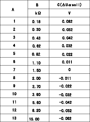
Compensation resistance/compensation voltage comparison
A = Compensation resistor number
B= Compensation resistance
C = Compensation voltage delta U alpha soll
----------
----------
----------
----------
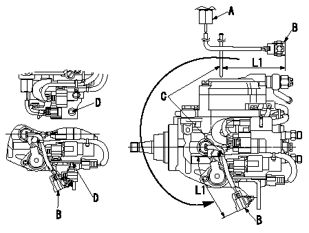
0000001601 HARNESS & CONNECTOR
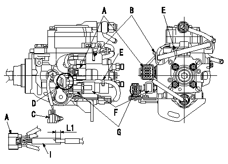
Connector and binder assembly specification
(1)For A's connector, adjust the position of the protective tube to L1 and install.
(2)After assembling the connector and bushing-type clip, fix the FCV harness and the GE cable using the clip B.
(3)Route the harness at D from the front to the T.P.S., to the Q adjustment and then to the T.C.V. in that order.
(4)At the next step, fix C's P/U connector harness using the clip.
A:GE, FCV, TCV and Q adjustment connectors.
B:Binder
C:Speed pickup connector
E:Push type clip
F:Q adjustment resistor
G:T.P.S. Connector
I:Protective tube
----------
----------
L1=10+-5mm
----------
----------
L1=10+-5mm
0000001701 HARNESS & CONNECTOR
P/U Harness position specification
Caution: The P/U connector is not fixed to the bracket.
(1)With the clip L1 from end of the connector, gather and fix the P/U and TPS harness.
(2)After fixing the clip, confirm that the P/U connector can be installed to the bracket installation hole. However, do not fix the connector to the bracket.
A:P/U
B:P/U Connector
C:Binder
D:Connector installation bracket hole
----------
----------
L1=(100mm)
----------
----------
L1=(100mm)
0000001801 HARNESS & CONNECTOR
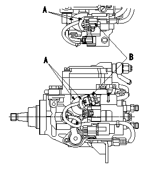
P/U connector temporary fixing specifications
(1)Confirm that the P/U connector can be installed to the bracket's installation hole.
(2)Position the P/U connector and harness between the GE cable and the FCV harness and temporarily fix the connector.
A:Position between the GE cable and the FCV harness.
B:P/U Connector
----------
----------
----------
----------
Information:
Illustration 39 g00367353
Set the drive speed to "Col 4". Place a straight edge across the opening in the shutdown rod and the shutdown rod nut (F). Use a 7/16 inch open end wrench in order to turn the shutdown rod nut (F) counterclockwise until the governor begins to shut down. Once the governor begins to shut down, turn the nut clockwise one full turn.Adjustment Of The Shutdown Device
Note: The electric shutdown device and the pressure shutdown device should be checked prior to the installation, after the installation, and at 1000 hour intervals thereafter.
Failure to test, inspect and maintain these items could result in faulty operation and possible severe engine damage if an emergency shutdown situation occurs.
The electric shutdown is either an Energize-To-Shutoff (ETS) or an Energize-To-Run (ETR). Identify the type of shutdown device in your governor, and make a note of the type of shutdown device.
Visually inspect the pressure shutdown components for signs of burrs, nicks, scoring and/or wear. Repair the components if evidence of a problem exists. Inspect the pressure shutdown gasket. Determine if the gasket is reusable. If necessary, replace the gasket.
Illustration 40 g00367319
(F) Shutdown Rod Nut. (J) Shutdown Rod. (II) Solenoid. (JJ) Jam Nut. (KK) Set Screw. (LL) Shutdown Plunger. (MM) Solenoid Plunger. (NN) Pivot Pin. (PP) Shutdown Lever.
Visually inspect the electric shutdown device and determine if there is any component wear. If the shutdown is an ETS version, pay particular attention to the connection of the shutdown solenoid's plunger and the shutdown lever's link pin.If there is evidence of wear, replace the solenoid. Inspect the gasket on the electric shutdown. Determine if the gasket is reusable. If necessary, replace the gasket.Check the size of spacer on the solenoid plunger in the electric shutdown. Refer to the Service Magazine Article November 19,, "Field Replacement of Spacer to Correct Possible Sticking in Woodward 3161 Governor Electric Shutoff Group".Adjustment Of The Electric Shutdown Solenoid
Energize-To-Shutoff (ETS)
Place the housing of the electric shutdown in a vise. Use copper jaws or shop towels in order to protect the sides of the aluminum die cast housing. Do NOT excessively tighten the vise.Loosen the jam nut (JJ) that holds the solenoid in the electric shutdown's housing. Remove the solenoid coil (II) in order to expose the shutdown plunger (MM) .Note: Loctite 222 is used on the threads of the solenoid coil during manufacturing. In addition, the jam nut is tightened to a torque of 75 N m (55.5 lb ft).
Carefully clean any dirt, metal filings or metal chips from the solenoid plunger and from the cavity in the solenoid coil. Turn the jam nut on the solenoid coil so that the nut will not interfere with the adjustment of the solenoid coil. Reinstall the solenoid coil in the electric shutdown's housing by turning the coil four times.
Hold the housing and the gasket on a
Have questions with 104700-0512?
Group cross 104700-0512 ZEXEL
Mazda
Mazda
104700-0512
9 460 613 193
RF1G13800D
INJECTION-PUMP ASSEMBLY
RF
RF