Information injection-pump assembly
BOSCH
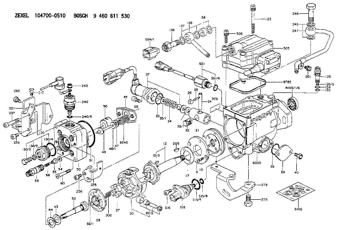
9 460 611 530
9460611530
ZEXEL
104700-0510
1047000510
Rating:
Components :
| 0. | INJECTION-PUMP ASSEMBLY | 104700-0510 |
| 1. | _ | |
| 2. | FUEL INJECTION PUMP | 104600-0510 |
| 3. | NUMBER PLATE | 148636-0800 |
| 4. | _ | |
| 5. | CAPSULE | |
| 6. | ADJUSTING DEVICE | |
| 7. | NOZZLE AND HOLDER ASSY | 105148-1531 |
| 8. | Nozzle and Holder | RF1G 13 H50B |
| 9. | Open Pre:MPa(Kqf/cm2) | 14.7{150} |
| 10. | NOZZLE-HOLDER | 105078-0111 |
| 11. | NOZZLE | 105007-1370 |
Scheme ###:
| 1/6. | [1] | 146601-0700 | PACKING RING |
| 6. | [1] | 146100-0120 | SUPPLY PUMP |
| 9. | [1] | 148103-0400 | COVER |
| 10. | [2] | 139104-0000 | FLAT-HEAD SCREW |
| 12. | [1] | 148200-0920 | DRIVE SHAFT |
| 12/3. | [1] | 146201-0000 | WOODRUFF KEY |
| 17. | [1] | 146204-0000 | PLAIN WASHER |
| 20. | [1] | 148210-0420 | ROLLER SET |
| 24. | [1] | 146303-0000 | BEARING PIN |
| 25. | [1] | 146304-0000 | BEARING PIN |
| 26. | [1] | 146305-0000 | CLAMPING BAND |
| 27. | [1] | 146205-0000 | SLOTTED WASHER |
| 29. | [1] | 146220-4820 | CAM PLATE |
| 30. | [1] | 146600-3000 | O-RING |
| 31. | [1] | 146300-1900 | PUMP PLUNGER |
| 32. | [1] | 146301-0200 | SLIDING PIECE |
| 33. | [1] | 146603-0700 | SHIM D17.5&7.5T0.60 |
| 34. | [1] | 146306-2100 | COMPRESSION SPRING |
| 35/1. | [0] | 146603-0700 | SHIM D17.5&7.5T0.60 |
| 35/1. | [0] | 146603-0800 | SHIM D17.5&7.5T0.70 |
| 35/1. | [0] | 146603-0900 | SHIM D17.5&7.5T0.90 |
| 35/1. | [0] | 146603-1000 | SHIM D17.5&7.5T1.00 |
| 35/1. | [0] | 146603-1100 | SHIM D17.5&7.5T1.20 |
| 35/1. | [0] | 146603-3600 | SHIM D17.5&7.5T2.40 |
| 36. | [1] | 146600-3000 | O-RING |
| 37. | [1] | 479765-1320 | TIMER PISTON SENSOR |
| 38. | [2] | 010206-2040 | HEX-SOCKET-HEAD CAP SCREW |
| 39. | [1] | 146310-0100 | COVER |
| 40. | [2] | 146620-5000 | BLEEDER SCREW |
| 43. | [1] | 146230-0000 | SHIM |
| 44. | [1] | 146230-0100 | PLAIN WASHER |
| 45. | [1] | 146231-0001 | SLOTTED WASHER |
| 47. | [2] | 146233-0000 | SLOTTED WASHER |
| 48/1. | [1] | 146603-0000 | SHIM D17.0&5.2T0.50 |
| 48/1. | [1] | 146603-0100 | SHIM D17.0&5.2T0.80 |
| 48/1. | [1] | 146603-0200 | SHIM D17.0&5.2T1.00 |
| 48/1. | [1] | 146603-0300 | SHIM D17.0&5.2T1.20 |
| 48/1. | [1] | 146603-0400 | SHIM D17.0&5.2T1.50 |
| 48/1. | [1] | 146603-0500 | SHIM D17.0&5.2T1.80 |
| 48/1. | [1] | 146603-0600 | SHIM D17.0&5.2T2.00 |
| 48/1. | [1] | 146690-1400 | SHIM D17&5.2T0.9 |
| 48/1. | [1] | 146690-1500 | SHIM D17&5.2T1.1 |
| 48/1. | [1] | 146690-1600 | SHIM D17&5.2T1.3 |
| 48/1. | [1] | 146690-1700 | SHIM D17&5.2T1.4 |
| 48/1. | [1] | 146690-1800 | SHIM D17&5.2T1.6 |
| 48/1. | [1] | 146690-1900 | SHIM D17&5.2T1.7 |
| 48/1. | [1] | 146690-5800 | SHIM D17&5.2T2.1 |
| 48/1. | [1] | 146690-5900 | SHIM D17&5.2T2.2 |
| 48/1. | [1] | 146690-6000 | SHIM |
| 48/1. | [1] | 146690-6100 | SHIM D17&5.2T2.4 |
| 48/1. | [1] | 146690-6200 | SHIM D17&5.2T2.5 |
| 48/1. | [1] | 146690-6300 | SHIM D17&5.2T2.6 |
| 48/1. | [1] | 146690-6400 | SHIM D17&5.2T2.7 |
| 48/1. | [1] | 146690-6500 | SHIM |
| 48/1. | [1] | 146690-6600 | SHIM |
| 48/1. | [1] | 146690-6700 | SHIM D17&5.2T3.0 |
| 48/1. | [1] | 146690-6800 | SHIM D17&5.2T3.1 |
| 48/1. | [1] | 146690-6900 | SHIM |
| 48/1. | [1] | 146690-7000 | SHIM |
| 48/1. | [1] | 146690-7100 | SHIM |
| 48/1. | [1] | 146690-7200 | SHIM D17&5.2T0.4 |
| 48/1. | [1] | 146690-7300 | SHIM |
| 48/1. | [1] | 146690-7400 | SHIM |
| 48/1. | [1] | 146690-7500 | SHIM |
| 48/1. | [1] | 146690-7800 | SHIM D17&5.2T0.2 |
| 49. | [2] | 146234-0120 | GUIDE PIN |
| 50. | [1] | 146403-8220 | HYDRAULIC HEAD |
| 50. | [1] | 146403-8220 | HYDRAULIC HEAD |
| 50. | [1] | 146403-8220 | HYDRAULIC HEAD |
| 51. | [1] | 146600-0000 | O-RING |
| 52/1. | [1] | 146420-0000 | SHIM D9.5&3.0T1.90 |
| 52/1. | [1] | 146420-0100 | SHIM D9.5&3.0T1.92 |
| 52/1. | [1] | 146420-0200 | SHIM D9.5&3.0T1.94 |
| 52/1. | [1] | 146420-0300 | SHIM D9.5&3.0T1.96 |
| 52/1. | [1] | 146420-0400 | SHIM D9.5&3.0T1.98 |
| 52/1. | [1] | 146420-0500 | SHIM D9.5&3.0T2.00 |
| 52/1. | [1] | 146420-0600 | SHIM D9.5&3.0T2.02 |
| 52/1. | [1] | 146420-0700 | SHIM D9.5&3.0T2.04 |
| 52/1. | [1] | 146420-0800 | SHIM D9.5&3.0T2.06 |
| 52/1. | [1] | 146420-0900 | SHIM D9.5&3.0T2.08 |
| 52/1. | [1] | 146420-1000 | SHIM D9.5&3.0T2.10 |
| 52/1. | [1] | 146420-1100 | SHIM D9.5&3.0T2.12 |
| 52/1. | [1] | 146420-1200 | SHIM D9.5&3.0T2.14 |
| 52/1. | [1] | 146420-1300 | SHIM D9.5&3.0T2.16 |
| 52/1. | [1] | 146420-1400 | SHIM D9.5&3.0T2.18 |
| 52/1. | [1] | 146420-1500 | SHIM D9.5&3.0T2.20 |
| 52/1. | [1] | 146420-1600 | SHIM D9.5&3.0T2.22 |
| 52/1. | [1] | 146420-1700 | SHIM D9.5&3.0T2.24 |
| 52/1. | [1] | 146420-1800 | SHIM D9.5&3.0T2.26 |
| 52/1. | [1] | 146420-1900 | SHIM D9.5&3.0T2.28 |
| 52/1. | [1] | 146420-2000 | SHIM D9.5&3.0T2.30 |
| 52/1. | [1] | 146420-2100 | SHIM D9.5&3.0T2.32 |
| 52/1. | [1] | 146420-2200 | SHIM D9.5&3.0T2.34 |
| 52/1. | [1] | 146420-2300 | SHIM D9.5&3.0T2.36 |
| 52/1. | [1] | 146420-2400 | SHIM D9.5&3.0T2.38 |
| 52/1. | [1] | 146420-2500 | SHIM D9.5&3.0T2.40 |
| 52/1. | [1] | 146420-2600 | SHIM D9.5&3.0T2.42 |
| 52/1. | [1] | 146420-2700 | SHIM D9.5&3.0T2.44 |
| 52/1. | [1] | 146420-2800 | SHIM D9.5&3.0T2.46 |
| 52/1. | [1] | 146420-2900 | SHIM D9.5&3.0T2.48 |
| 52/1. | [1] | 146420-3000 | SHIM D9.5&3.0T2.50 |
| 52/1. | [1] | 146420-3100 | SHIM D9.5&3.0T2.52 |
| 52/1. | [1] | 146420-3200 | SHIM D9.5&3.0T2.54 |
| 52/1. | [1] | 146420-3300 | SHIM D9.5&3.0T2.56 |
| 52/1. | [1] | 146420-3400 | SHIM D9.5&3.0T2.58 |
| 52/1. | [1] | 146420-3500 | SHIM D9.5&3.0T2.60 |
| 52/1. | [1] | 146420-3600 | SHIM D9.5&3.0T2.62 |
| 52/1. | [1] | 146420-3700 | SHIM D9.5&3.0T2.64 |
| 52/1. | [1] | 146420-3800 | SHIM D9.5&3.0T2.66 |
| 52/1. | [1] | 146420-3900 | SHIM D9.5&3.0T2.68 |
| 52/1. | [1] | 146420-4000 | SHIM D9.5&3.0T2.70 |
| 52/1. | [1] | 146420-4100 | SHIM D9.5&3.0T2.72 |
| 52/1. | [1] | 146420-4200 | SHIM D9.5&3.0T2.74 |
| 52/1. | [1] | 146420-4300 | SHIM D9.5&3.0T2.76 |
| 52/1. | [1] | 146420-4400 | SHIM D9.5&3.0T2.78 |
| 52/1. | [1] | 146420-4500 | SHIM D9.5&3.0T2.80 |
| 52/1. | [1] | 146420-4600 | SHIM D9.5&3.0T2.82 |
| 52/1. | [1] | 146420-4700 | SHIM D9.5&3.0T2.84 |
| 52/1. | [1] | 146420-4800 | SHIM D9.5&3.0T2.86 |
| 52/1. | [1] | 146420-4900 | SHIM D9.5&3.0T2.88 |
| 52/1. | [1] | 146420-5000 | SHIM D9.5&3.0T2.90 |
| 52/1. | [1] | 146420-5100 | SHIM D9.5&3.0T1.74 |
| 52/1. | [1] | 146420-5200 | SHIM D9.5&3.0T1.76 |
| 52/1. | [1] | 146420-5300 | SHIM D9.5&3.0T1.78 |
| 52/1. | [1] | 146420-5400 | SHIM D9.5&3.0T1.80 |
| 52/1. | [1] | 146420-5500 | SHIM D9.5&3.0T1.82 |
| 52/1. | [1] | 146420-5600 | SHIM D9.5&3.0T1.84 |
| 52/1. | [1] | 146420-5700 | SHIM D9.5&3.0T1.86 |
| 52/1. | [1] | 146420-5800 | SHIM D9.5&3.0T1.88 |
| 54. | [4] | 146433-0100 | GASKET D12&6.4T1.00 |
| 55. | [4] | 146430-0320 | DELIVERY-VALVE ASSEMBLY |
| 56. | [4] | 146432-0000 | COMPRESSION SPRING |
| 58. | [4] | 146440-0220 | FITTING |
| 60. | [3] | 139106-0100 | FLAT-HEAD SCREW |
| 123. | [1] | 146620-8800 | FLAT-HEAD SCREW |
| 130. | [1] | 146421-1020 | CAPSULE |
| 130/2. | [1] | 139508-0200 | GASKET D11.4&8.2T1 |
| 130/3. | [1] | 146422-0300 | BLEEDER SCREW |
| 130/4. | [1] | 146600-0500 | O-RING |
| 133. | [1] | 146600-0600 | O-RING |
| 134. | [1] | 146600-0700 | O-RING |
| 135. | [1] | 146110-3220 | CONTROL VALVE |
| 135/5. | [1] | 146114-0000 | SPRING WASHER |
| 136. | [1] | 148120-0020 | OVER FLOW VALVE |
| 137. | [3] | 139512-0500 | GASKET |
| 138. | [1] | 146669-0920 | INLET UNION |
| 158. | [1] | 146614-6900 | SPACER BUSHING |
| 200. | [1] | 146206-0100 | COILED SPRING |
| 205. | [1] | 029470-4030 | WOODRUFF KEY |
| 221. | [1] | 148613-2720 | BRACKET |
| 235. | [1] | 148613-2800 | BRACKET |
| 236. | [2] | 146620-2700 | HEX-SOCKET-HEAD CAP SCREW |
| 236. | [2] | 146620-2700 | HEX-SOCKET-HEAD CAP SCREW |
| 237. | [1] | 146620-0200 | HEX-SOCKET-HEAD CAP SCREW |
| 240. | [1] | 146688-0920 | PULLING ELECTROMAGNET |
| 240/8. | [1] | 146600-1700 | O-RING |
| 243. | [1] | 146621-1000 | UNION NUT |
| 245. | [2] | 139512-0500 | GASKET |
| 246. | [1] | 027412-2440 | EYE BOLT |
| 247. | [1] | 146669-1020 | INLET UNION |
| 251. | [1] | 020145-1040 | BLEEDER SCREW |
| 275. | [1] | 148612-1120 | BRACKET |
| 276. | [2] | 010010-1640 | BLEEDER SCREW M10P1.5L16 4T |
| 282. | [1] | 139006-4400 | BLEEDER SCREW |
| 317. | [1] | 139006-5700 | BLEEDER SCREW |
| 504/1. | [1] | 146649-4500 | RESISTER |
| 504/1. | [1] | 146649-4600 | RESISTER |
| 504/1. | [1] | 146649-4700 | RESISTER |
| 504/1. | [1] | 146649-4800 | RESISTER |
| 504/1. | [1] | 146649-4900 | RESISTER |
| 504/1. | [1] | 146649-5000 | RESISTER |
| 504/1. | [1] | 146649-5100 | RESISTER |
| 504/1. | [1] | 146649-5200 | RESISTER |
| 504/1. | [1] | 146649-5300 | RESISTER |
| 504/1. | [1] | 146649-5400 | RESISTER |
| 504/1. | [1] | 146649-5500 | RESISTER |
| 504/1. | [1] | 146649-5600 | RESISTER |
| 504/1. | [1] | 146649-5700 | RESISTER |
| 505. | [1] | 148531-2220 | GOVERNOR;ELECTRIC |
| 506. | [3] | 146620-8900 | FLAT-HEAD SCREW |
| 515. | [1] | 106144-1070 | TIMING CONTROL VALVE |
| 515/8. | [1] | 161440-3800 | O-RING |
| 515/9. | [1] | 161440-3700 | O-RING |
| 516. | [2] | 010206-1440 | HEX-SOCKET-HEAD CAP SCREW M6P1L14 |
| 531. | [1] | 479765-1020 | PULSE GENERATOR |
| 531/6. | [1] | 479773-6500 | O-RING |
| 800S. | [1] | 148009-0620 | PUMP HOUSING |
| 800S/1/6. | [1] | 146601-0700 | PACKING RING |
| 804S. | [1] | 146232-0720 | COMPRESSION SPRING |
| 810S. | [1] | 146600-4620 | REPAIR SET |
| 821S. | [1] | 146210-5820 | ROLLER SET |
| 878S. | [1] | 148600-1300 | SEAL RING |
| 906. | [1] | 148636-0800 | NAMEPLATE |
Include in #2:
104700-0510
as INJECTION-PUMP ASSEMBLY
Cross reference number
BOSCH
9 460 611 530
9460611530
ZEXEL
104700-0510
1047000510
Zexel num
Bosch num
Firm num
Name
Calibration Data:
Adjustment conditions
Test oil
1404 Test oil ISO4113orSAEJ967d
1404 Test oil ISO4113orSAEJ967d
Test oil temperature
degC
45
45
50
Nozzle
105780-0060
Bosch type code
NP-DN0SD1510
Nozzle holder
105780-2150
Opening pressure
MPa
13
13
13.3
Opening pressure
kgf/cm2
133
133
136
Injection pipe
157805-7320
Injection pipe
Inside diameter - outside diameter - length (mm) mm 2-6-450
Inside diameter - outside diameter - length (mm) mm 2-6-450
Joint assembly
157641-4720
Tube assembly
157641-4020
Transfer pump pressure
kPa
20
20
20
Transfer pump pressure
kgf/cm2
0.2
0.2
0.2
Direction of rotation (viewed from drive side)
Right R
Right R
Governor adjustment
Pump speed
r/min
750
750
750
TCV duty (%) F TCV 60Hz
%
100
100
100
U alpha soll
V
2.7
2.7
2.7
Pump chamber pressure
kPa
539.5
510
569
Pump chamber pressure
kgf/cm2
5.5
5.2
5.8
Basic
*
Governor adjustment_02
Pump speed
r/min
100
100
100
TCV duty (%) F TCV 60Hz
%
100
100
100
U alpha soll
V
2.7
2.7
2.7
Pump chamber pressure
kPa
294
294
Pump chamber pressure
kgf/cm2
3
3
Governor adjustment_03
Pump speed
r/min
750
750
750
TCV duty (%) F TCV 60Hz
%
100
100
100
U alpha soll
V
2.7
2.7
2.7
Pump chamber pressure
kPa
539.5
500
579
Pump chamber pressure
kgf/cm2
5.5
5.1
5.9
Governor adjustment_04
Pump speed
r/min
2250
2250
2250
TCV duty (%) F TCV 60Hz
%
100
100
100
U alpha soll
V
2.7
2.7
2.7
Pump chamber pressure
kPa
745
696
794
Pump chamber pressure
kgf/cm2
7.6
7.1
8.1
Boost compensator adjustment
Pump speed
r/min
750
750
750
TCV duty (%) F TCV 60Hz
%
100
100
100
U alpha soll
V
2.7
2.7
2.7
Timer stroke
mm
7
6.8
7.2
Basic
*
Boost compensator adjustment_02
Pump speed
r/min
100
100
100
TCV duty (%) F TCV 60Hz
%
100
100
100
U alpha soll
V
2.7
2.7
2.7
Timer stroke
mm
3.5
1.5
5.5
Boost compensator adjustment_03
Pump speed
r/min
360
360
360
TCV duty (%) F TCV 60Hz
%
100
100
100
U alpha soll
V
2.7
2.7
2.7
Timer stroke
mm
6.9
4.9
8.9
Boost compensator adjustment_04
Pump speed
r/min
750
750
750
TCV duty (%) F TCV 60Hz
%
100
100
100
U alpha soll
V
2.7
2.7
2.7
Timer stroke
mm
7
6.7
7.3
Boost compensator adjustment_05
Pump speed
r/min
750
750
750
TCV duty (%) F TCV 60Hz
%
70
70
70
U alpha soll
V
2.7
2.7
2.7
Timer stroke
mm
3.6
1.6
5.6
Boost compensator adjustment_06
Pump speed
r/min
2250
2250
2250
TCV duty (%) F TCV 60Hz
%
100
100
100
U alpha soll
V
2.7
2.7
2.7
Timer stroke
mm
9.85
9.3
10.4
Boost compensator adjustment_07
Pump speed
r/min
2250
2250
2250
TCV duty (%) F TCV 60Hz
%
0
0
0
U alpha soll
V
2.7
2.7
2.7
Timer stroke
mm
0
0
0
Timer adjustment
Pump speed
r/min
750
750
750
TCV duty (%) F TCV 60Hz
%
0
0
0
U alpha soll
V
2.7
2.7
2.7
Vtps
V
0.51
0.382
0.638
Basic
*
Timer adjustment_02
Pump speed
r/min
750
750
750
TCV duty (%) F TCV 60Hz
%
0
0
0
U alpha soll
V
2.7
2.7
2.7
Vtps
V
0.51
0.382
0.638
Timer adjustment_03
Pump speed
r/min
750
750
750
TCV duty (%) F TCV 60Hz
%
100
100
100
U alpha soll
V
2.7
2.7
2.7
Vtps
V
1.796
1.591
2.001
Speed control lever angle
Pump speed
r/min
1000
1000
1000
TCV duty (%) F TCV 60Hz
%
100
100
100
U alpha soll
V
2.7
2.7
2.7
Overflow quantity
cm3/min
510
380
640
0000000901
Pump speed
r/min
1250
1250
1250
U alpha soll + dU alpha soll
V
2.49
2.49
2.49
TCV duty (%) F TCV 60Hz
%
100
100
100
Average injection quantity
mm3/st.
43.1
42.6
43.6
Difference in delivery
mm3/st.
4
Basic
*
_02
Pump speed
r/min
413
413
413
U alpha soll + dU alpha soll
V
1.87
1.87
1.87
TCV duty (%) F TCV 60Hz
%
100
100
100
Average injection quantity
mm3/st.
7.4
4.4
10.4
Difference in delivery
mm3/st.
1.5
Basic
*
Remarks
Confirmation of difference in delivery
Confirmation of difference in delivery
_03
Pump speed
r/min
2600
2600
2600
U alpha soll + dU alpha soll
V
1.82
1.82
1.82
TCV duty (%) F TCV 60Hz
%
100
100
100
Average injection quantity
mm3/st.
14
11.5
16.5
Difference in delivery
mm3/st.
5
Basic
*
Remarks
Confirmation of difference in delivery
Confirmation of difference in delivery
_04
Pump speed
r/min
100
100
100
U alpha soll + dU alpha soll
V
2.76
2.76
2.76
TCV duty (%) F TCV 60Hz
%
100
100
100
Average injection quantity
mm3/st.
31.7
21.7
41.7
_05
Pump speed
r/min
413
413
413
U alpha soll + dU alpha soll
V
1.87
1.87
1.87
TCV duty (%) F TCV 60Hz
%
100
100
100
Average injection quantity
mm3/st.
7.4
4.4
10.4
_06
Pump speed
r/min
450
450
450
U alpha soll + dU alpha soll
V
1.87
1.87
1.87
TCV duty (%) F TCV 60Hz
%
100
100
100
Average injection quantity
mm3/st.
10.2
7.2
13.2
_07
Pump speed
r/min
500
500
500
U alpha soll + dU alpha soll
V
2.47
2.47
2.47
TCV duty (%) F TCV 60Hz
%
100
100
100
Average injection quantity
mm3/st.
40.9
38.4
43.4
_08
Pump speed
r/min
570
570
570
U alpha soll + dU alpha soll
V
1.87
1.87
1.87
TCV duty (%) F TCV 60Hz
%
100
100
100
Average injection quantity
mm3/st.
6.1
3.1
9.1
_09
Pump speed
r/min
1250
1250
1250
U alpha soll + dU alpha soll
V
2
2
2
TCV duty (%) F TCV 60Hz
%
100
100
100
Average injection quantity
mm3/st.
19.2
16.7
21.7
_10
Pump speed
r/min
1250
1250
1250
U alpha soll + dU alpha soll
V
2.49
2.49
2.49
TCV duty (%) F TCV 60Hz
%
100
100
100
Average injection quantity
mm3/st.
43.1
42.1
44.1
_11
Pump speed
r/min
1500
1500
1500
U alpha soll + dU alpha soll
V
2.42
2.42
2.42
TCV duty (%) F TCV 60Hz
%
100
100
100
Average injection quantity
mm3/st.
39.8
37.3
42.3
_12
Pump speed
r/min
1750
1750
1750
U alpha soll + dU alpha soll
V
2.42
2.42
2.42
TCV duty (%) F TCV 60Hz
%
100
100
100
Average injection quantity
mm3/st.
41.3
38.8
43.8
_13
Pump speed
r/min
2250
2250
2250
U alpha soll + dU alpha soll
V
2.43
2.43
2.43
TCV duty (%) F TCV 60Hz
%
100
100
100
Average injection quantity
mm3/st.
40.5
38
43
_14
Pump speed
r/min
2350
2350
2350
U alpha soll + dU alpha soll
V
2.41
2.41
2.41
TCV duty (%) F TCV 60Hz
%
100
100
100
Average injection quantity
mm3/st.
39.2
36.7
41.7
_15
Pump speed
r/min
2600
2600
2600
U alpha soll + dU alpha soll
V
1
1
1
TCV duty (%) F TCV 60Hz
%
100
100
100
Average injection quantity
mm3/st.
3
_16
Pump speed
r/min
2600
2600
2600
U alpha soll + dU alpha soll
V
1.82
1.82
1.82
TCV duty (%) F TCV 60Hz
%
100
100
100
Average injection quantity
mm3/st.
14
11.5
16.5
Stop lever angle
Pump speed
r/min
413
413
413
U alpha soll + dU alpha soll
V
1.87
1.87
1.87
TCV duty (%) F TCV 60Hz
%
0
0
0
Average injection quantity
cm3/min
0
0
0
Stop lever angle_02
Pump speed
r/min
2350
2350
2350
U alpha soll + dU alpha soll
V
2.41
2.41
2.41
TCV duty (%) F TCV 60Hz
%
100
100
100
Average injection quantity
cm3/min
0
0
0
0000001101
Pump speed
r/min
200
200
200
TCV duty (%) F TCV 60Hz
%
100
100
100
U alpha soll
V
2.7
2.7
2.7
Speed output
N=Measure the actual speed. r/min N+-8
N=Measure the actual speed. r/min N+-8
0000001201
Pump speed
r/min
1250
1250
1250
TCV duty (%) F TCV 60Hz
%
100
100
100
U alpha soll
V
2.49
2.49
2.49
Temperature output
Measure T = actual output temperature degC T+-5
Measure T = actual output temperature degC T+-5
0000001301
Max. applied voltage
V
8
8
8
Test voltage
V
13
12
14
0000001401
K dimension
mm
3.3
3.2
3.4
KF dimension
mm
5.8
5.7
5.9
Pre-stroke
mm
0.1
0.08
0.12
Test data Ex:
Injection timing adjustment Comp. resistor/voltage
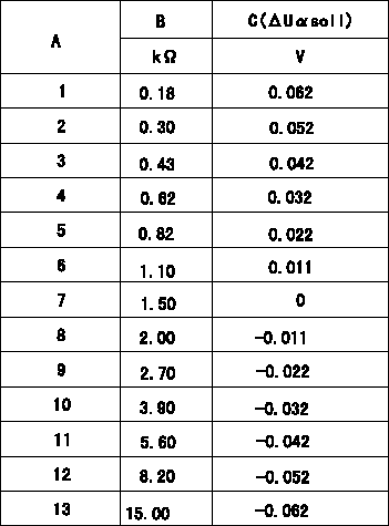
Compensation resistance/compensation voltage comparison
A = Compensation resistor number
B= Compensation resistance
C = Compensation voltage delta U alpha soll
----------
----------
----------
----------
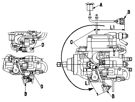
0000001601 HARNESS & CONNECTOR
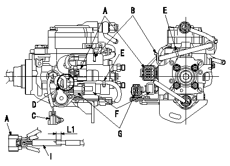
Connector and binder assembly specification
(1)For A's connector, adjust the position of the protective tube to L1 and install.
(2)After assembling the connector and bushing-type clip, fix the FCV harness and the GE cable using the clip B.
(3)Route the harness at D from the front to the T.P.S., to the Q adjustment and then to the T.C.V. in that order.
(4)At the next step, fix C's P/U connector harness using the clip.
A:GE, FCV, TCV and Q adjustment connectors.
B:Binder
C:Speed pickup connector
E:Push type clip
F:Q adjustment resistor
G:T.P.S. Connector
I:Protective tube
----------
----------
L1=10+-5mm
----------
----------
L1=10+-5mm
0000001701 HARNESS & CONNECTOR
P/U Harness position specification
Caution: The P/U connector is not fixed to the bracket.
(1)With the clip L1 from end of the connector, gather and fix the P/U and TPS harness.
(2)After fixing the clip, confirm that the P/U connector can be installed to the bracket installation hole. However, do not fix the connector to the bracket.
A:P/U
B:P/U Connector
C:Binder
D:Connector installation bracket hole
----------
----------
L1=(100mm)
----------
----------
L1=(100mm)
0000001801 HARNESS & CONNECTOR
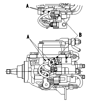
P/U connector temporary fixing specifications
(1)Confirm that the P/U connector can be installed to the bracket's installation hole.
(2)Position the P/U connector and harness between the GE cable and the FCV harness and temporarily fix the connector.
A:Position between the GE cable and the FCV harness.
B:P/U Connector
----------
----------
----------
----------
Information:
General Recommendations and Contamination Control Guidelines for Fuels
Follow all applicable industry standards and all applicable governmental, environmental, and safety guidelines, practices, regulations, and mandates.Note: These general recommendations and guidelines concerning maintenance and care of fuel and fuel storage systems are not intended to be all inclusive. Discuss proper fuel safety and health, handling, and maintenance practices with your fuel supplier. Use of these general recommendations and guidelines does not lessen the engine owners and/or fuel supplier responsibility to follow all industry standard practices for fuel storage and for fuel handling.Note: Where recommendations for draining water and/or sediment and/or debris are stated, dispose of this waste according to all applicable regulations and mandates.Note: Caterpillar filters are designed and built to provide optimal performance and protection of the fuel system components.Clean fuels, as detailed below, are strongly recommended to allow optimal performance and durability of the fuel systems and to reduce power loss, failures, and related down time of engines.Fuels of “ISO 18/16/13” cleanliness levels or cleaner as dispensed into the engine or machine fuel tank should be used. Reduced power, failures and related downtime can result if clean fuels are not used. Fuels of “ISO 18/16/13” are particularly important for new fuel system designs such as Common Rail injection systems and unit injection systems. These new injection system designs utilize higher fuel pressures and are designed with tight clearances between moving parts to meet required stringent emissions regulations. Peak injection pressures in current fuel injection systems may exceed 30,000 psi. Clearances in these systems are less than 5 µm. As a result, particle contaminants as small as 4 µm can cause scoring and scratching of internal pump and injector surfaces and of injector nozzles.Water in the fuel causes cavitation, corrosion of fuel system parts, and provides an environment where microbial growth in the fuel can flourish. Other sources of fuel contamination are soaps, gels, or other compounds that may result from undesirable chemical interactions in the fuels. Gels and other insoluble compounds can also form in biodiesel fuel at low temperatures or if biodiesel is stored for extended periods. An indication of microbial contamination, detrimental fuel additives interactions, or cold temperature gel is very rapid filter plugging of bulk fuel filters or machine fuel filters.To reduce downtime due to contamination, follow these fuel maintenance guidelines in addition to the recommendations given in the "Contamination Control" Chapter in this Special Publication:
Use high-quality fuels per recommended and required specifications (refer to the “Fuel” chapter in this Special Publication).
Do not add new engine oil, waste engine oil or any oil product to the fuel unless the engine is designed and certified to burn diesel engine oil (for example Caterpillar ORS designed for large engines). Engine oils may raise the sulfur level of the fuel and may cause fouling of the fuel system and loss of performance. Engine oils in fuels can also reduce the maintenance intervals of aftertreatment devices in Tier 4 machines.
Use recommended Cat filtration products, including Cat Advanced Efficiency Fuel