Information injection-pump assembly
ZEXEL
104304-4342
1043044342
ISUZU
8944068902
8944068902
Rating:
Cross reference number
ZEXEL
104304-4342
1043044342
ISUZU
8944068902
8944068902
Zexel num
Bosch num
Firm num
Name
Calibration Data:
Adjustment conditions
Test oil
1404 Test oil ISO4113 or {SAEJ967d}
1404 Test oil ISO4113 or {SAEJ967d}
Test oil temperature
degC
40
40
45
Nozzle and nozzle holder
105780-8140
Bosch type code
EF8511/9A
Nozzle
105780-0000
Bosch type code
DN12SD12T
Nozzle holder
105780-2080
Bosch type code
EF8511/9
Opening pressure
MPa
17.2
Opening pressure
kgf/cm2
175
Injection pipe
Outer diameter - inner diameter - length (mm) mm 6-2-600
Outer diameter - inner diameter - length (mm) mm 6-2-600
Tester oil delivery pressure
kPa
157
157
157
Tester oil delivery pressure
kgf/cm2
1.6
1.6
1.6
Direction of rotation (viewed from drive side)
Right R
Right R
Injection timing adjustment
Direction of rotation (viewed from drive side)
Right R
Right R
Injection order
1-3-4-2
Pre-stroke
mm
2.1
2.05
2.15
Rack position
Point A R=A
Point A R=A
Beginning of injection position
Drive side NO.1
Drive side NO.1
Difference between angles 1
Cal 1-3 deg. 90 89.5 90.5
Cal 1-3 deg. 90 89.5 90.5
Difference between angles 2
Cal 1-4 deg. 180 179.5 180.5
Cal 1-4 deg. 180 179.5 180.5
Difference between angles 3
Cyl.1-2 deg. 270 269.5 270.5
Cyl.1-2 deg. 270 269.5 270.5
Injection quantity adjustment
Adjusting point
A
Rack position
8.2
Pump speed
r/min
1000
1000
1000
Average injection quantity
mm3/st.
25.6
23.6
27.6
Max. variation between cylinders
%
0
-4
4
Fixing the lever
*
Injection quantity adjustment_02
Adjusting point
B
Rack position
7.8
Pump speed
r/min
1250
1250
1250
Average injection quantity
mm3/st.
26.4
25.4
27.4
Max. variation between cylinders
%
0
-2.5
2.5
Basic
*
Fixing the lever
*
Injection quantity adjustment_03
Adjusting point
-
Rack position
7.3+-0.5
Pump speed
r/min
375
375
375
Average injection quantity
mm3/st.
7.6
6.6
8.6
Max. variation between cylinders
%
0
-14
14
Fixing the lever
*
Remarks
Adjust only variation between cylinders; adjust governor according to governor specifications.
Adjust only variation between cylinders; adjust governor according to governor specifications.
Injection quantity adjustment_04
Adjusting point
D
Rack position
13+1
Pump speed
r/min
100
100
100
Average injection quantity
mm3/st.
34.4
34.4
Fixing the lever
*
Test data Ex:
Governor adjustment
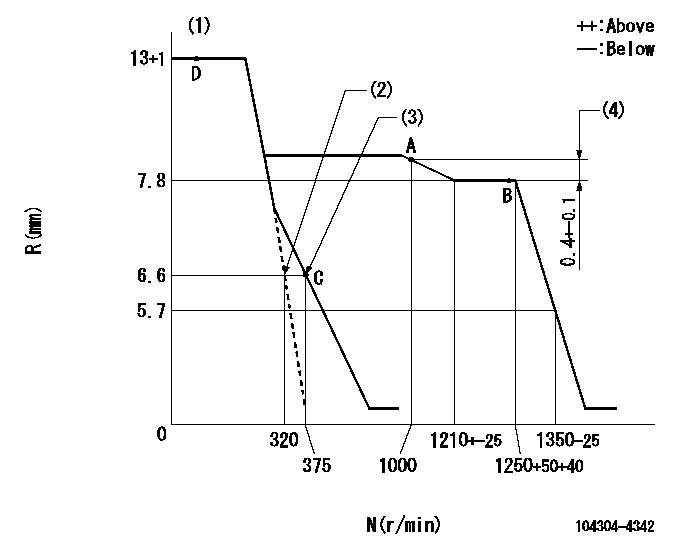
N:Pump speed
R:Rack position (mm)
(1)Torque control stroke: L1
(2)Set the idle spring.
(3)Main spring setting
(4)Rack difference from N = N1
----------
L1=0.4mm N1=1250r/min
----------
----------
L1=0.4mm N1=1250r/min
----------
Speed control lever angle

F:Full speed
I:Idle
(1)Stopper bolt setting
----------
----------
a=7deg+-3deg b=25deg+-6deg
----------
----------
a=7deg+-3deg b=25deg+-6deg
Stop lever angle
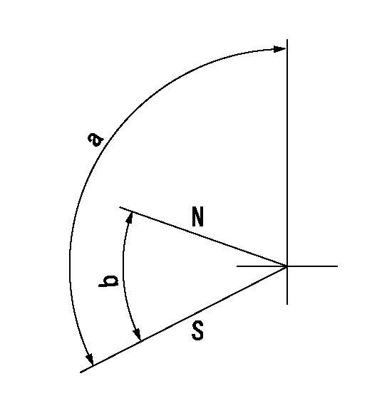
N:Pump normal
S:Stop the pump.
----------
----------
a=100deg+-5deg b=(38deg)
----------
----------
a=100deg+-5deg b=(38deg)
Timing setting

(1)Pump vertical direction
(2)Position of gear's standard threaded hole at No 1 cylinder's beginning of injection
(3)B.T.D.C.: aa
(4)-
----------
aa=17deg
----------
a=(50deg)
----------
aa=17deg
----------
a=(50deg)
Information:
ACTION REQUIRED
New DEF system software is available that reduces the risk of an internal DEF injector leak by improved temperature management. Please update the DEF system software at the next opportunity.
Ensure that all adjustments and repairs that are carried out to the Diesel Emission Fluid (DEF) system are performed by authorized personnel that have the correct training. Before beginning ANY work on the DEF system, refer to Operation and Maintenance Manual, "General Hazard" for safety information.
Before Failure:
Check that the engine software is the latest version before updating the DEF pump software.
If the engine software is not the latest version, update the Engine Software first.
If needed, update the engine software with the latest available in SIS Web.
Flash the DEF Pump ECM with the software listed in the Parts Needed or latest available in SIS Web.
For flash programming of the ECM software, refer to Troubleshooting "ECM Software - Install".
After Failure:
Ensure the appropriate steps have been followed when diagnosing a DEF injector failure. Refer to UENR0662.
If it is determined that replacement of DEF injector is required, refer to Disassembly and Assembly Manual - Diesel Exhaust Fluid Injector - Remove and Install.
After the DEF injector has been replaced, perform the DEF system software update as detailed in the "Before Failure" section above.
SERVICE CLAIM ALLOWANCES
Product smu/age whichever comes first Caterpillar Dealer Suggested Customer Suggested
Parts % Labor Hrs% Parts % Labor Hrs% Parts % Labor Hrs%
*******Group 1*******
0-5000 hrs,
0-60 mo 100.0% 100.0% 0.0% 0.0% 0.0% 0.0%
This is a 0.5-hour job for Group 1
An additional 2 hours are allowed for After failure
Product smu/age whichever comes first Caterpillar Dealer Suggested Customer Suggested
Parts % Labor Hrs% Parts % Labor Hrs% Parts % Labor Hrs%
*******Group 2*******
0-5000 hrs,
0-60 mo 100.0% 100.0% 0.0% 0.0% 0.0% 0.0%
This is a 0.5-hour job for Group 2
An additional 2 hours are allowed for After failure
PARTS DISPOSITION
Handle the parts in accordance with your Warranty Bulletin on warranty parts handling.