Information injection-pump assembly
BOSCH
9 400 616 507
9400616507
ZEXEL
104304-3251
1043043251
ISHIKAWAJIMA-S
131017270
131017270

Rating:
Service parts 104304-3251 INJECTION-PUMP ASSEMBLY:
1.
_
3.
GOVERNOR
5.
AUTOM. ADVANCE MECHANIS
6.
COUPLING PLATE
7.
COUPLING PLATE
8.
_
9.
_
10.
NOZZLE AND HOLDER ASSY
11.
Nozzle and Holder
12.
Open Pre:MPa(Kqf/cm2)
13.
NOZZLE-HOLDER
14.
NOZZLE
15.
NOZZLE SET
Include in #1:
104304-3251
as INJECTION-PUMP ASSEMBLY
Cross reference number
BOSCH
9 400 616 507
9400616507
ZEXEL
104304-3251
1043043251
ISHIKAWAJIMA-S
131017270
131017270
Zexel num
Bosch num
Firm num
Name
104304-3251
9 400 616 507
131017270 ISHIKAWAJIMA-S
INJECTION-PUMP ASSEMBLY
T854B * K 14BX PES4K PE
T854B * K 14BX PES4K PE
Calibration Data:
Adjustment conditions
Test oil
1404 Test oil ISO4113 or {SAEJ967d}
1404 Test oil ISO4113 or {SAEJ967d}
Test oil temperature
degC
40
40
45
Nozzle and nozzle holder
105780-8140
Bosch type code
EF8511/9A
Nozzle
105780-0000
Bosch type code
DN12SD12T
Nozzle holder
105780-2080
Bosch type code
EF8511/9
Opening pressure
MPa
17.2
Opening pressure
kgf/cm2
175
Injection pipe
Outer diameter - inner diameter - length (mm) mm 6-2-600
Outer diameter - inner diameter - length (mm) mm 6-2-600
Tester oil delivery pressure
kPa
157
157
157
Tester oil delivery pressure
kgf/cm2
1.6
1.6
1.6
Direction of rotation (viewed from drive side)
Right R
Right R
Injection timing adjustment
Direction of rotation (viewed from drive side)
Right R
Right R
Injection order
1-3-4-2
Pre-stroke
mm
1.95
1.9
2
Beginning of injection position
Drive side NO.1
Drive side NO.1
Difference between angles 1
Cal 1-3 deg. 90 89.5 90.5
Cal 1-3 deg. 90 89.5 90.5
Difference between angles 2
Cal 1-4 deg. 180 179.5 180.5
Cal 1-4 deg. 180 179.5 180.5
Difference between angles 3
Cyl.1-2 deg. 270 269.5 270.5
Cyl.1-2 deg. 270 269.5 270.5
Injection quantity adjustment
Adjusting point
A
Rack position
R1(10.1)
Pump speed
r/min
800
800
800
Average injection quantity
mm3/st.
41
40
42
Max. variation between cylinders
%
0
-3
3
Basic
*
Fixing the lever
*
Injection quantity adjustment_02
Adjusting point
C
Rack position
5+-0.5
Pump speed
r/min
400
400
400
Average injection quantity
mm3/st.
6
5
7
Max. variation between cylinders
%
0
-14
14
Fixing the lever
*
Test data Ex:
Governor adjustment
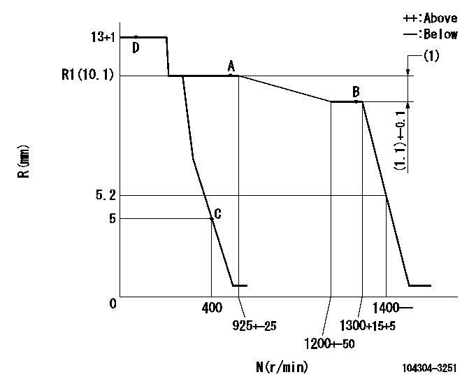
N:Pump speed
R:Rack position (mm)
(1)Rack difference between N = N1 and N = N2
----------
N1=1300r/min N2=800r/min
----------
----------
N1=1300r/min N2=800r/min
----------
Speed control lever angle

F:Full speed
I:Idle
(1)Stopper bolt setting
----------
----------
a=21deg+-3deg b=28deg+-6deg
----------
----------
a=21deg+-3deg b=28deg+-6deg
Stop lever angle

N:Pump normal
S:Stop the pump.
----------
----------
a=10deg+2deg-5deg b=(38deg)
----------
----------
a=10deg+2deg-5deg b=(38deg)
Information:
Do not put oil on the bearings until the bearing clearance has been checked.1. Install bearings (1) in the connecting rods they were removed from. Make sure the tab in each bearing is in alignment with the notch in each connecting rod.2. Install bearings (2) in the cylinder block. Make sure the tab in each bearing is in alignment with the notch in the cylinder block. 3. Install pin (3) in the end of the crankshaft. Install the pin so that it extends a maximum of 6.4 mm (.252 in) above the surface. 4. Install the dowel in the crankshaft that puts gear (4) in the correct position. Install the dowel so that it extends 4.1 0.5 mm (.161 .020 in) above the surface of the crankshaft.5. Heat gear (4) to a maximum temperature of 233° C (451° F). Gear (4) must be installed on the crankshaft with the "V" timing mark toward the outside.6. Install gear (4) on the crankshaft. Make sure the notch in the gear is in alignment with the dowel on the crankshaft. The dimension from the rear face of the gear to the front face of the crankshaft must be 45.54 0.25 mm (1.793 .010 in). 7. Fasten Tooling (A) and a hoist to the crankshaft (5) as shown. Install the crankshaft in the engine. The weight of the crankshaft is approximately 131 kg (290 lb). 8. Make sure that "V" mark (6) on the crankshaft is in alignment with "V" mark (7) on the idler gear. The side of each thrust plate (8) with the words "BLOCK SIDE" must be installed with this side toward the cylinder block.9. Put clean oil on thrust plates (8). Install thrust plates (8) next to the center main bearings. Do not put oil on bearings (9) until the bearing clearances have been checked.10. Put bearings (9) in their original position in crankshaft main bearing caps (10).11. Check the crankshaft main bearing clearance with Plastigage as follows:a. Put a piece of Plastigage between the crankshaft bearing journal surface and bearing (9).b. Install the crankshaft main bearing caps (10) with the arrow on each cap toward the front of cylinder block. Each crankshaft main bearing cap has a number on the bottom surface and must be installed in the same position as the correct number on the left side of the cylinder block.c. Put 2P-2506 Thread Lubricant on the threads of the cap bolts. Install the cap bolts finger tight.d. Tighten the bolts on the tab end of the caps first to a torque of 258 14 N m (190 10 lb ft).e. Tighten the bolts on the other end of the caps to a torque of 258 14 N m (190 10 lb ft).
Do not use an impact wrench to tighten the bolts the additional 120 degrees.
f. Put a mark across the bolt head and cap. Tighten the bolts opposite the tab end of the cap
Do not use an impact wrench to tighten the bolts the additional 120 degrees.
f. Put a mark across the bolt head and cap. Tighten the bolts opposite the tab end of the cap
Have questions with 104304-3251?
Group cross 104304-3251 ZEXEL
Ishikawajima-S
Isuzu
Ishikawajima-S
104304-3251
9 400 616 507
131017270
INJECTION-PUMP ASSEMBLY
T854B
T854B