Information injection-pump assembly
BOSCH
9 400 616 506
9400616506
ZEXEL
104304-3240
1043043240
ISHIKAWAJIMA-S
131017260
131017260

Rating:
Service parts 104304-3240 INJECTION-PUMP ASSEMBLY:
1.
_
3.
GOVERNOR
5.
AUTOM. ADVANCE MECHANIS
6.
COUPLING PLATE
7.
COUPLING PLATE
8.
_
9.
_
10.
NOZZLE AND HOLDER ASSY
11.
Nozzle and Holder
12.
Open Pre:MPa(Kqf/cm2)
13.
NOZZLE-HOLDER
14.
NOZZLE
15.
NOZZLE SET
Include in #1:
104304-3240
as INJECTION-PUMP ASSEMBLY
Cross reference number
BOSCH
9 400 616 506
9400616506
ZEXEL
104304-3240
1043043240
ISHIKAWAJIMA-S
131017260
131017260
Zexel num
Bosch num
Firm num
Name
104304-3240
9 400 616 506
131017260 ISHIKAWAJIMA-S
INJECTION-PUMP ASSEMBLY
T854BT * K
T854BT * K
Calibration Data:
Adjustment conditions
Test oil
1404 Test oil ISO4113 or {SAEJ967d}
1404 Test oil ISO4113 or {SAEJ967d}
Test oil temperature
degC
40
40
45
Nozzle and nozzle holder
105780-8140
Bosch type code
EF8511/9A
Nozzle
105780-0000
Bosch type code
DN12SD12T
Nozzle holder
105780-2080
Bosch type code
EF8511/9
Opening pressure
MPa
17.2
Opening pressure
kgf/cm2
175
Injection pipe
Outer diameter - inner diameter - length (mm) mm 6-2-600
Outer diameter - inner diameter - length (mm) mm 6-2-600
Tester oil delivery pressure
kPa
157
157
157
Tester oil delivery pressure
kgf/cm2
1.6
1.6
1.6
Direction of rotation (viewed from drive side)
Right R
Right R
Injection timing adjustment
Direction of rotation (viewed from drive side)
Right R
Right R
Injection order
1-3-4-2
Pre-stroke
mm
1.95
1.9
2
Beginning of injection position
Drive side NO.1
Drive side NO.1
Difference between angles 1
Cal 1-3 deg. 90 89.5 90.5
Cal 1-3 deg. 90 89.5 90.5
Difference between angles 2
Cal 1-4 deg. 180 179.5 180.5
Cal 1-4 deg. 180 179.5 180.5
Difference between angles 3
Cyl.1-2 deg. 270 269.5 270.5
Cyl.1-2 deg. 270 269.5 270.5
Injection quantity adjustment
Adjusting point
A
Rack position
11.8
Pump speed
r/min
750
750
750
Average injection quantity
mm3/st.
50.5
49.5
51.5
Max. variation between cylinders
%
0
-3
3
Basic
*
Fixing the lever
*
Injection quantity adjustment_02
Adjusting point
C
Rack position
5.8+-0.5
Pump speed
r/min
375
375
375
Average injection quantity
mm3/st.
7.7
6.7
8.7
Max. variation between cylinders
%
0
-14
14
Fixing the rack
*
Test data Ex:
Governor adjustment
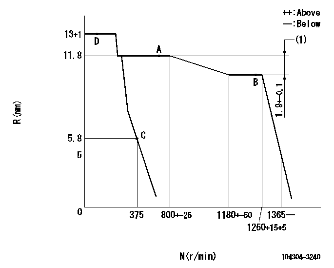
N:Pump speed
R:Rack position (mm)
(1)Rack difference between N = N1 and N = N2
----------
N1=1250r/min N2=750r/min
----------
----------
N1=1250r/min N2=750r/min
----------
Speed control lever angle
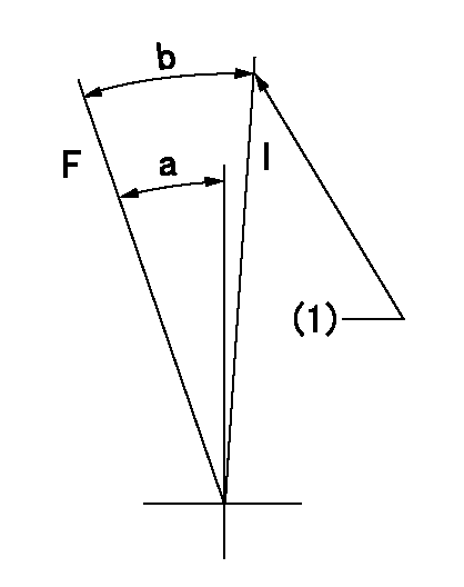
F:Full speed
I:Idle
(1)Stopper bolt setting
----------
----------
a=21deg+-3deg b=25deg+-6deg
----------
----------
a=21deg+-3deg b=25deg+-6deg
Stop lever angle

N:Pump normal
S:Stop the pump.
----------
----------
a=10deg+2deg-5deg b=(38deg)
----------
----------
a=10deg+2deg-5deg b=(38deg)
Information:
Start By:a. remove oil pump1. Check the identification marks on the connecting rods and caps as to their location in the engine. The caps must be installed in original positions in the engine.2. Turn the crankshaft until two of the pistons are at bottom center. 3. Remove connecting rod caps (1) from the connecting rods. Remove the lower half of the bearings from the caps.
Be careful not to damage the crankshaft journals. Do not turn the crankshaft while any of the connecting rod caps are removed.
4. Push the connecting rod away from the crankshaft, and remove the upper half of the bearings from the connecting rods.5. Make sure the surface of the connecting rod where the bearings make contact is clean and free of dirt.
Make sure the tabs on the bearings are in alignment with the notches in the connecting rods and caps.
6. Install the upper half of new bearings in the connecting rods.7. Pull the connecting rod down slowly on the crankshaft.
Make sure the surfaces where the bearings make contact in the caps are clean and free of dirt.
8. Install new bearings (2) in the caps. Make sure the tabs on the bearings are in alignment with the notches in the caps.The serviceman must be very careful to use Plastigage correctly. The following points must be remembered:... Make sure that the backs of the bearings and the bores are clean and dry.... Make sure that the bearing locking tabs are properly seated in their slots.... The crankshaft must be free of oil where the Plastigage touches it.... Put a piece of Plastigage on the crown of the bearing half that is in the cap. Do not allow the Plastigage to extend over the edge of the bearing.... Install the bearing cap using the correct torque-turn specifications. Do not use an impact wrench. Be careful not to dislodge the bearing when the cap is installed.... Do not turn the crankshaft with the Plastigage installed. ... Carefully remove the cap but do not remove the Plastigage. Measure the width of the Plastigage while it is in the bearing cap or on the crankshaft journal. Do this by using the correct scale on the package. Record the measurements.... Remove the Plastigage before installing the cap.When using Plastigage, the readings can sometimes be unclear. For example, all parts of the Plastigage are not the same width. Measure the major widths to make sure that they are within the specification range. Also, experience has shown that when checking clearances tighter than 0.10 mm (.004 in) the readings may be low by 0.013 to 0.025 mm (.0005 to .0010 in). Out-of-round journals can give faulty readings. Also, journal taper may be indicated when one end of the Plastigage is wider that the other.For complete details concerning measuring bearing clearances, see Engine Bearings & Crankshafts, SEBD0531.9. Put 2P-2506 Thread Lubricant on the threads of the bolts in the connecting rods.10. Check the bearing clearance with Plastigage (A) as follows:
When Plastigage is used to check
Have questions with 104304-3240?
Group cross 104304-3240 ZEXEL
Ishikawajima-S
Isuzu
Ishikawajima-S
104304-3240
9 400 616 506
131017260
INJECTION-PUMP ASSEMBLY
T854BT
T854BT