Information injection-pump assembly
BOSCH
9 400 616 504
9400616504
ZEXEL
104304-3210
1043043210
ISHIKAWAJIMA-S
131017170
131017170

Rating:
Cross reference number
BOSCH
9 400 616 504
9400616504
ZEXEL
104304-3210
1043043210
ISHIKAWAJIMA-S
131017170
131017170
Zexel num
Bosch num
Firm num
Name
104304-3210
9 400 616 504
131017170 ISHIKAWAJIMA-S
INJECTION-PUMP ASSEMBLY
T854 * K
T854 * K
Calibration Data:
Adjustment conditions
Test oil
1404 Test oil ISO4113 or {SAEJ967d}
1404 Test oil ISO4113 or {SAEJ967d}
Test oil temperature
degC
40
40
45
Nozzle and nozzle holder
105780-8140
Bosch type code
EF8511/9A
Nozzle
105780-0000
Bosch type code
DN12SD12T
Nozzle holder
105780-2080
Bosch type code
EF8511/9
Opening pressure
MPa
17.2
Opening pressure
kgf/cm2
175
Injection pipe
Outer diameter - inner diameter - length (mm) mm 6-2-600
Outer diameter - inner diameter - length (mm) mm 6-2-600
Tester oil delivery pressure
kPa
157
157
157
Tester oil delivery pressure
kgf/cm2
1.6
1.6
1.6
Direction of rotation (viewed from drive side)
Right R
Right R
Injection timing adjustment
Direction of rotation (viewed from drive side)
Right R
Right R
Injection order
1-3-4-2
Pre-stroke
mm
1.95
1.9
2
Beginning of injection position
Drive side NO.1
Drive side NO.1
Difference between angles 1
Cal 1-3 deg. 90 89.5 90.5
Cal 1-3 deg. 90 89.5 90.5
Difference between angles 2
Cal 1-4 deg. 180 179.5 180.5
Cal 1-4 deg. 180 179.5 180.5
Difference between angles 3
Cyl.1-2 deg. 270 269.5 270.5
Cyl.1-2 deg. 270 269.5 270.5
Injection quantity adjustment
Adjusting point
A
Rack position
10
Pump speed
r/min
750
750
750
Average injection quantity
mm3/st.
39.7
38.7
40.7
Max. variation between cylinders
%
0
-3
3
Basic
*
Fixing the lever
*
Injection quantity adjustment_02
Adjusting point
C
Rack position
5+-0.5
Pump speed
r/min
400
400
400
Average injection quantity
mm3/st.
6
5
7
Max. variation between cylinders
%
0
-14
14
Fixing the lever
*
Test data Ex:
Governor adjustment
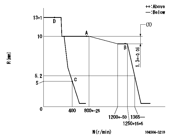
N:Pump speed
R:Rack position (mm)
(1)Rack difference between N = N1 and N = N2
----------
N1=1250r/min N2=750r/min
----------
----------
N1=1250r/min N2=750r/min
----------
Speed control lever angle
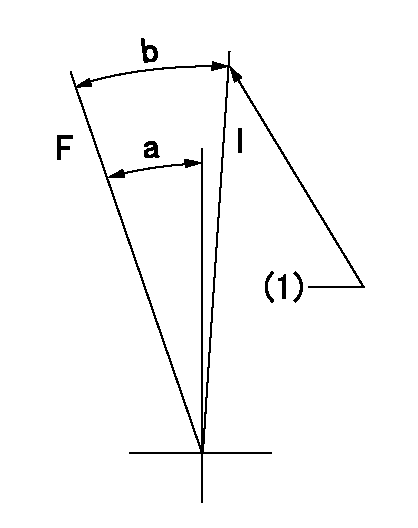
F:Full speed
I:Idle
(1)Stopper bolt setting
----------
----------
a=21deg+-3deg b=25deg+-6deg
----------
----------
a=21deg+-3deg b=25deg+-6deg
Stop lever angle

N:Pump normal
S:Stop the pump.
----------
----------
a=19deg+-3deg b=(38deg)
----------
----------
a=19deg+-3deg b=(38deg)
Information:
Start By:a. remove valve covers
Do not let the tops of the fuel injection nozzles turn when the fuel lines are loosened. The nozzles will be damaged if the top of the nozzles turn in the body.
1. Use Tooling (A) to loosen the nuts on the fuel injection line.2. Remove fuel injection lines (1).3. Disconnect fuel injection line nut (2) from head adapter nut (3).4. Remove adapter nut (3) and the O-ring seal. 5. Remove four bolts (4) that hold rocker arm assembly (5), and remove rocker arm assembly (5).Install Rocker Shaft Assemblies
1. Check the adjustment of the valve bridges. See the topic "Install Push Rods, Valve Lifters & Valve Bridges" in this module. 2. Loosen all the rocker arm adjusting screws on rocker shaft assembly (5).3. Install rocker shaft assembly (5).4. Clean the bolts that hold the rocker shaft assembly. Put 2P-2506 Thread Lubricant on the bolt threads, and install them.5. Be sure the rocker arms and push rods are in alignment before the rocker shaft assembly bolts are tightened.6. Tighten the rocker shaft bolts in the following sequence.a. Tighten bolts (1) through (4) in numerical sequence to a torque of 280 27 N m (210 20 lb ft).b. Tighten bolts (1) through (4) in numerical sequence to a torque of 440 20 N m (320 15 lb ft).c. Tighten bolts (1) through (4) in numerical sequence again to a final torque of 440 20 N m (320 15 lb ft). 7. Install a new O-ring seal on head adapter (7), and put clean engine oil on it.8. Put fuel injection line (8) in position, but do not tighten the nuts.9. Install adapters (7), and connect fuel injection lines (8).10. Connect fuel injection lines (6) to adapters (7).
Do not let the tops of the fuel injection nozzles turn when the fuel lines are tightened. The nozzles will be damaged if the top of the nozzles turn in the body.
11. Use Tooling (A) to tighten the fuel injection line nuts to a torque of 41 7 N m (30 5 lb ft).12. Adjust the valve clearance settings. The clearance for the intake valve is 0.38 mm (.015 in). The clearance for the exhaust valves is 0.76 mm (.030 in). See the topic "Valve Clearance Setting" in Testing & Adjusting.End By:a. install valve coversDisassemble Rocker Shaft Assemblies
Start By:a. remove rocker shaft assemblies 1. Remove retainer (1) from the end of the shaft.2. Remove the washers and rocker arm (2). 3. Use Tool (A) to remove the pin that holds bracket (3) to the rocker arm shaft.4. Remove bracket (3), rocker arm (4) and the spring.5. Remove the remainder of the rocker arms. The center brackets do not have pins.Assemble Rocker Shaft Assemblies
Make sure all parts of the rocker shaft assembly are clean before assembly. 1. Put clean engine oil on shaft (3).2. Install the center springs, rocker arms and bracket.3. Install spring (1), rocker arm (4) and bracket (2).4. Put tape
Have questions with 104304-3210?
Group cross 104304-3210 ZEXEL
Ishikawajima-S
104304-3210
9 400 616 504
131017170
INJECTION-PUMP ASSEMBLY
T854
T854