Information injection-pump assembly
BOSCH
9 400 616 503
9400616503
ZEXEL
104304-3200
1043043200
ISHIKAWAJIMA-S
131017150
131017150

Rating:
Cross reference number
BOSCH
9 400 616 503
9400616503
ZEXEL
104304-3200
1043043200
ISHIKAWAJIMA-S
131017150
131017150
Zexel num
Bosch num
Firm num
Name
104304-3200
9 400 616 503
131017150 ISHIKAWAJIMA-S
INJECTION-PUMP ASSEMBLY
T854 * K 14BX PES4K PE
T854 * K 14BX PES4K PE
Calibration Data:
Adjustment conditions
Test oil
1404 Test oil ISO4113 or {SAEJ967d}
1404 Test oil ISO4113 or {SAEJ967d}
Test oil temperature
degC
40
40
45
Nozzle and nozzle holder
105780-8140
Bosch type code
EF8511/9A
Nozzle
105780-0000
Bosch type code
DN12SD12T
Nozzle holder
105780-2080
Bosch type code
EF8511/9
Opening pressure
MPa
17.2
Opening pressure
kgf/cm2
175
Injection pipe
Outer diameter - inner diameter - length (mm) mm 6-2-600
Outer diameter - inner diameter - length (mm) mm 6-2-600
Tester oil delivery pressure
kPa
157
157
157
Tester oil delivery pressure
kgf/cm2
1.6
1.6
1.6
Direction of rotation (viewed from drive side)
Right R
Right R
Injection timing adjustment
Direction of rotation (viewed from drive side)
Right R
Right R
Injection order
1-3-4-2
Pre-stroke
mm
1.95
1.9
2
Beginning of injection position
Drive side NO.1
Drive side NO.1
Difference between angles 1
Cal 1-3 deg. 90 89.5 90.5
Cal 1-3 deg. 90 89.5 90.5
Difference between angles 2
Cal 1-4 deg. 180 179.5 180.5
Cal 1-4 deg. 180 179.5 180.5
Difference between angles 3
Cyl.1-2 deg. 270 269.5 270.5
Cyl.1-2 deg. 270 269.5 270.5
Injection quantity adjustment
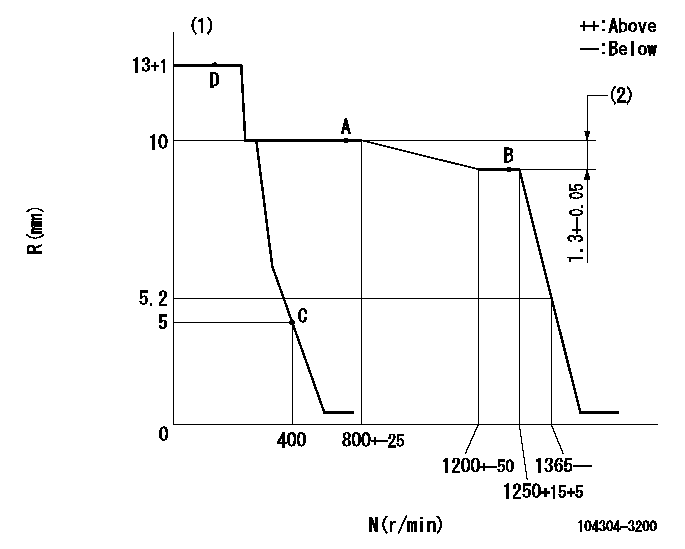
Adjusting point
A
Rack position
10
Pump speed
r/min
750
750
750
Average injection quantity
mm3/st.
39.7
38.7
40.7
Max. variation between cylinders
%
0
-3
3
Basic
*
Fixing the lever
*
Injection quantity adjustment_02
Adjusting point
C
Rack position
5+-0.5
Pump speed
r/min
400
400
400
Average injection quantity
mm3/st.
6
5
7
Max. variation between cylinders
%
0
-14
14
Fixing the lever
*
Test data Ex:
Governor adjustment
N:Pump speed
R:Rack position (mm)
(1)Rack difference between N = N1 and N = N2
----------
N1=1250r/min N2=750r/min
----------
----------
N1=1250r/min N2=750r/min
----------
Speed control lever angle
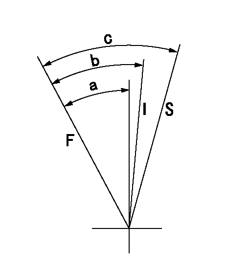
F:Full speed
I:Idle
S:Stop
----------
----------
a=21deg+-3deg b=25deg+-6deg c=(35deg)
----------
----------
a=21deg+-3deg b=25deg+-6deg c=(35deg)
Information:
Start By:a. remove valve covers1. Turn the flywheel with Tool (C) until there is clearance between the rocker arms and valve bridges. 2. Engage Tool (A) with the rocker arm, and move Tool (A) against the valve spring force until push rod (1) can be removed.3. Remove the other push rod for the same cylinder. Mark each push rod so it can be installed in its original position. 4. Use Tool (B) to remove valve lifter (2).5. Remove the other valve lifter for the same cylinder. Mark each valve lifter so it can be installed in its original position. 6. Remove spring (3) from lifter (2).7. Inspect spring (3). See Guideline For Reusable Parts, SEBF8066. 8. Identify the location of each valve bridge (4), then remove them.Install Push Rods, Valve Lifters & Valve Bridges
1. Put clean engine oil on each bridge dowel and the bore of each bridge. Install bridges (1) in their original position.2. Use the following procedure to adjust the valve bridges.a. Put clean SAE 30 Engine Oil in the lubrication passage of the bridge.b. Press straight down on the top contact surface of the bridge with a force of 4.45 to 44.50 N (1 to 10 lb).c. Turn the adjusting screw clockwise until the oil film in the lubrication passage of the bridge moves inward.d. Turn the adjusting screw an additional 20 to 30 degrees (1/3 to 1/2 of a flat on the hex nut).e. Hold the adjusting screw in position, and tighten the locknut to a torque of 26 to 34 N m (19 to 25 lb ft).f. Do this procedure for both bridges. Put clean engine oil on the top contact surface of both bridges. 3. Install spring (3) on valve lifter (2). 4. Fasten Tool (A) to valve lifter (2).5. Immerse valve lifter (2) in clean engine oil; then install it in its original position.6. Install the other valve lifter for the same cylinder. 7. Engage Tool (B) with the rocker arm, and move Tool (B) against the valve spring force until push rods (4) can be installed in their original position.8. Use Tool (C) to turn the flywheel so the remaining push rods can be installed. Be sure there is clearance at the rocker arms and valve bridges before compressing the valve pump.9. Check the valve clearance settings. The clearance for the intake valves is 0.38 mm (.015 in). The clearance for the exhaust valve is 0.76 mm (.030 in). See the topic "Valve Clearance Setting" in Testing & Adjusting.End By:a. install valve covers
1. Put clean engine oil on each bridge dowel and the bore of each bridge. Install bridges (1) in their original position.2. Use the following procedure to adjust the valve bridges.a. Put clean SAE 30 Engine Oil in the lubrication passage of the bridge.b. Press straight down on the top contact surface of the bridge with a force of 4.45 to 44.50 N (1 to 10 lb).c. Turn the adjusting screw clockwise until the oil film in the lubrication passage of the bridge moves inward.d. Turn the adjusting screw an additional 20 to 30 degrees (1/3 to 1/2 of a flat on the hex nut).e. Hold the adjusting screw in position, and tighten the locknut to a torque of 26 to 34 N m (19 to 25 lb ft).f. Do this procedure for both bridges. Put clean engine oil on the top contact surface of both bridges. 3. Install spring (3) on valve lifter (2). 4. Fasten Tool (A) to valve lifter (2).5. Immerse valve lifter (2) in clean engine oil; then install it in its original position.6. Install the other valve lifter for the same cylinder. 7. Engage Tool (B) with the rocker arm, and move Tool (B) against the valve spring force until push rods (4) can be installed in their original position.8. Use Tool (C) to turn the flywheel so the remaining push rods can be installed. Be sure there is clearance at the rocker arms and valve bridges before compressing the valve pump.9. Check the valve clearance settings. The clearance for the intake valves is 0.38 mm (.015 in). The clearance for the exhaust valve is 0.76 mm (.030 in). See the topic "Valve Clearance Setting" in Testing & Adjusting.End By:a. install valve covers
Have questions with 104304-3200?
Group cross 104304-3200 ZEXEL
Ishikawajima-S
104304-3200
9 400 616 503
131017150
INJECTION-PUMP ASSEMBLY
T854
T854