Information injection-pump assembly
ZEXEL
104304-3130
1043043130
ISUZU
5156013831
5156013831

Rating:
Cross reference number
ZEXEL
104304-3130
1043043130
ISUZU
5156013831
5156013831
Zexel num
Bosch num
Firm num
Name
Calibration Data:
Adjustment conditions
Test oil
1404 Test oil ISO4113 or {SAEJ967d}
1404 Test oil ISO4113 or {SAEJ967d}
Test oil temperature
degC
40
40
45
Nozzle and nozzle holder
105780-8140
Bosch type code
EF8511/9A
Nozzle
105780-0000
Bosch type code
DN12SD12T
Nozzle holder
105780-2080
Bosch type code
EF8511/9
Opening pressure
MPa
17.2
Opening pressure
kgf/cm2
175
Injection pipe
Outer diameter - inner diameter - length (mm) mm 6-2-600
Outer diameter - inner diameter - length (mm) mm 6-2-600
Tester oil delivery pressure
kPa
157
157
157
Tester oil delivery pressure
kgf/cm2
1.6
1.6
1.6
Direction of rotation (viewed from drive side)
Right R
Right R
Injection timing adjustment
Direction of rotation (viewed from drive side)
Right R
Right R
Injection order
1-3-4-2
Pre-stroke
mm
2.1
2.05
2.15
Rack position
Point B R=B
Point B R=B
Beginning of injection position
Drive side NO.1
Drive side NO.1
Difference between angles 1
Cal 1-3 deg. 90 89.5 90.5
Cal 1-3 deg. 90 89.5 90.5
Difference between angles 2
Cal 1-4 deg. 180 179.5 180.5
Cal 1-4 deg. 180 179.5 180.5
Difference between angles 3
Cyl.1-2 deg. 270 269.5 270.5
Cyl.1-2 deg. 270 269.5 270.5
Injection quantity adjustment
Adjusting point
A
Rack position
8.9
Pump speed
r/min
700
700
700
Average injection quantity
mm3/st.
25.9
25.4
26.4
Max. variation between cylinders
%
0
-2.5
2.5
Basic
*
Fixing the lever
*
Injection quantity adjustment_02
Adjusting point
C
Rack position
6.8+-0.5
Pump speed
r/min
425
425
425
Average injection quantity
mm3/st.
8.7
7.7
9.7
Max. variation between cylinders
%
0
-14
14
Fixing the lever
*
Remarks
Adjust only variation between cylinders; adjust governor according to governor specifications.
Adjust only variation between cylinders; adjust governor according to governor specifications.
Test data Ex:
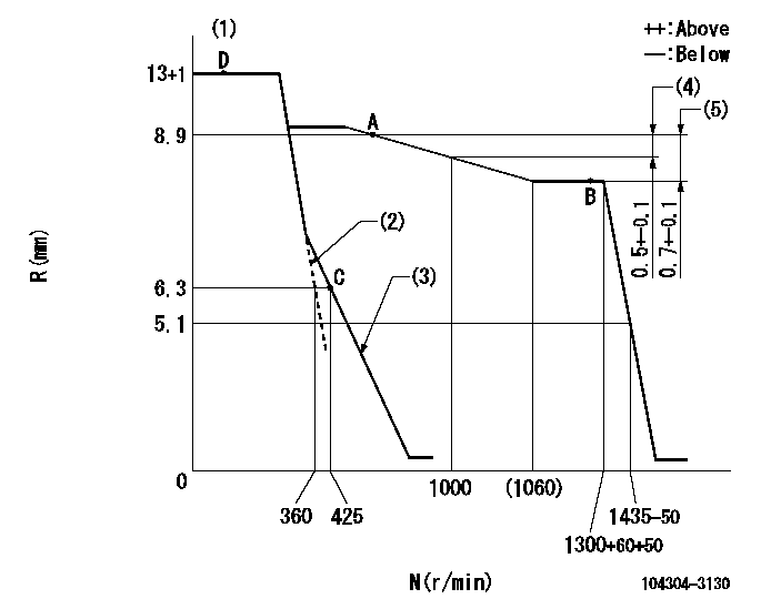
Governor adjustment

N:Pump speed
R:Rack position (mm)
(1)Torque control stroke: L1
(2)Set the idle spring.
(3)Main spring setting
(4)Rack difference between N = N1 and N = N2
(5)Rack difference between N = N3 and N = N4
----------
L1=0.9mm N1=1000r/min N2=700r/min N3=1300r/min N4=700r/min
----------
----------
L1=0.9mm N1=1000r/min N2=700r/min N3=1300r/min N4=700r/min
----------
Speed control lever angle

F:Full speed
I:Idle
----------
----------
a=7deg+-3deg b=28deg+-6deg
----------
----------
a=7deg+-3deg b=28deg+-6deg
Timing setting

(1)Pump vertical direction
(2)Position of gear's standard threaded hole at No 1 cylinder's beginning of injection (same as key groove position)
(3)B.T.D.C.: aa
(4)-
----------
aa=20deg
----------
a=(50deg)
----------
aa=20deg
----------
a=(50deg)
Information:
Typical Example2. Remove eight bolts (3) that fasten pipe (1) to the elbow. Remove four bolts (2) that fasten the elbow to the aftercooler cover. Remove elbow (4).
Typical Example3. Remove bracket (5) from the oil filter tube and the oil level gauge group.
Typical Example4. Remove four bolts (7) from the air inlet elbow. Remove plate (6) and elbow (8). 5. Remove two tubes (10) from the air compressor to the aftercooler.6. Remove elbows (9) from the aftercooler housing.
Typical Example
Put identification on bolts (12) because they are 6.4 mm (.25 in) longer than all other bolts. They must be installed in the same location.
7. Remove bolts (11) and (12) from cover, and remove the cover.
Put identification on bolt (14) because it is 12.7 mm (.50 in) shorter than all the other bolts. It must be installed in the same location. Remove four adapters (15). Put plugs in both holes in the aftercooler core assembly. This will keep coolant out of the engine intake manifold.
8. Remove bolts (13) and (14) that hold the core assembly in position.9. Remove the aftercooler core assembly. 10. Remove air line (17) from the fuel ratio control valve.11. Remove eight bolts (16). Remove housing assembly (18).Install Aftercooler
1. Check all seals and gaskets for damage. If damaged, use new parts for replacement.
All foreign material and dirt must be removed from the gasket surface and inside the housing and intake manifold.
2. Install housing (1) and air line (2) to the fuel control valve. 3. Install four new seals (3) on the core assembly. Put clean glycerin on the O-ring seals. 4. Install core assembly (4) inside the housing. Remove plugs in both holes of the aftercooler core assembly. Install the bolts that fasten the core to housing. Install the bolts in their original location. 5. Put clean engine oil in the bores of the adapters. Install adapters (5). 6. Put cover (6) in position on the aftercooler. Install the two bolts in position (7). These bolts are 6.4 mm (.25 in) longer than all other bolts around the housing. Install the remainder of the bolts around the housing. 7. Install elbows (8). 8. Install two tubes (9) between the air compressor and the aftercooler.
Typical Example9. Install elbow (10) and plate (11) on the aftercooler cover. Install the bracket that is a support for the oil filter tube and the oil level gauge group. Install the oil filter tube and the oil level gauge group.
Typical Example10. Install eight bolts (13) that fasten the pipe to elbow (14). Install the elbow in the turbocharger.11. Install the four bolts that fasten the elbow to aftercooler cover (12).12. Fill the engine with coolant to the correct level. See the Operation & Maintenance Manual.