Information injection-pump assembly
ZEXEL
104303-5181
1043035181
ISEKI
62156000361B
62156000361b

Rating:
Service parts 104303-5181 INJECTION-PUMP ASSEMBLY:
1.
_
3.
GOVERNOR
4.
SUPPLY PUMP
5.
AUTOM. ADVANCE MECHANIS
6.
COUPLING PLATE
7.
COUPLING PLATE
8.
_
9.
_
11.
Nozzle and Holder
6215300-0022
12.
Open Pre:MPa(Kqf/cm2)
20.6{210}
15.
NOZZLE SET
Include in #1:
104303-5181
as INJECTION-PUMP ASSEMBLY
Cross reference number
ZEXEL
104303-5181
1043035181
ISEKI
62156000361B
62156000361b
Zexel num
Bosch num
Firm num
Name
104303-5181
62156000361B ISEKI
INJECTION-PUMP ASSEMBLY
E3AF1 * K
E3AF1 * K
Calibration Data:
Adjustment conditions
Test oil
1404 Test oil ISO4113 or {SAEJ967d}
1404 Test oil ISO4113 or {SAEJ967d}
Test oil temperature
degC
40
40
45
Nozzle and nozzle holder
105780-8140
Bosch type code
EF8511/9A
Nozzle
105780-0000
Bosch type code
DN12SD12T
Nozzle holder
105780-2080
Bosch type code
EF8511/9
Opening pressure
MPa
17.2
Opening pressure
kgf/cm2
175
Injection pipe
Outer diameter - inner diameter - length (mm) mm 6-2-600
Outer diameter - inner diameter - length (mm) mm 6-2-600
Tester oil delivery pressure
kPa
157
157
157
Tester oil delivery pressure
kgf/cm2
1.6
1.6
1.6
Direction of rotation (viewed from drive side)
Right R
Right R
Injection timing adjustment
Direction of rotation (viewed from drive side)
Right R
Right R
Injection order
1-3-2
Pre-stroke
mm
2.8
2.75
2.85
Beginning of injection position
Drive side NO.1
Drive side NO.1
Difference between angles 1
Cal 1-3 deg. 120 119.5 120.5
Cal 1-3 deg. 120 119.5 120.5
Difference between angles 2
Cyl.1-2 deg. 240 239.5 240.5
Cyl.1-2 deg. 240 239.5 240.5
Injection quantity adjustment
Adjusting point
A
Rack position
R1(7.9)
Pump speed
r/min
1250
1250
1250
Average injection quantity
mm3/st.
30.6
29.6
31.6
Max. variation between cylinders
%
0
-2.5
2.5
Basic
*
Fixing the lever
*
Injection quantity adjustment_02
Adjusting point
-
Rack position
6.4+-0.5
Pump speed
r/min
425
425
425
Average injection quantity
mm3/st.
6.6
5.6
7.6
Max. variation between cylinders
%
0
-14
14
Fixing the lever
*
Remarks
Adjust only variation between cylinders; adjust governor according to governor specifications.
Adjust only variation between cylinders; adjust governor according to governor specifications.
Injection quantity adjustment_03
Adjusting point
C
Rack position
11+-0.5
Pump speed
r/min
100
100
100
Average injection quantity
mm3/st.
49
45
53
Fixing the lever
*
Rack limit
*
Test data Ex:
Governor adjustment
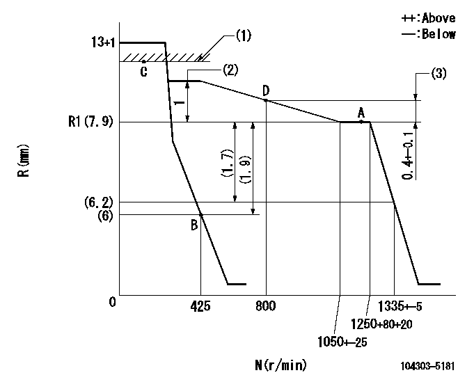
N:Pump speed
R:Rack position (mm)
(1)RACK LIMIT
(2)Torque control stroke
(3)Rack difference between N = N1 and N = N2
----------
N1=1250r/min N2=800r/min
----------
----------
N1=1250r/min N2=800r/min
----------
Speed control lever angle

F:Full speed
I:Idle
(1)Stopper bolt setting
----------
----------
a=12deg+-3deg b=21deg+-6deg
----------
----------
a=12deg+-3deg b=21deg+-6deg
Timing setting

(1)Pump vertical direction
(2)Position of gear mark '00' at No 1 cylinder's beginning of injection
(3)B.T.D.C.: aa
(4)-
----------
aa=18deg
----------
a=(110deg)
----------
aa=18deg
----------
a=(110deg)
Information:
1. Drain the coolant from the cooling system to a level below that of the water pump.2. Remove elbow (1).3. Remove bolts (4) that hold cover (2) to the water pump. Remove bolts (5) that hold elbow (3) to cover (2).4. Remove line (6).5. Remove cover (2). Remove elbow (3). 6. Remove four bolts (7).7. Remove nuts (8) and one bolt (not shown). Remove water pump.Install Water Pump
1. Put the water pump in position on the timing gear cover. Install nuts (8) and one bolt that hold the pump to the timing gear cover.2. Install four bolts (7). 3. Put clean engine oil or glycerin on O-ring seals (9). Install elbow (3). 4. Put cover (2) in position on the water pump. Install bolts (4) that hold the cover to the water pump and bolts (5) that hold elbow (3) to the cover.5. Install elbow (1).6. Install line (6).7. Fill the cooling system to the proper level. See the Operation & Maintenance Manual.Disassemble Water Pump
Start By:a. remove water pump 1. Remove O-ring seal (1) from adapter (2).2. Remove adapter (2) with a screwdriver. Remove the seal from the edge of adapter (2).3. Remove bolt (3) and washer. 4. Remove impeller (4) from the water pump housing with Tooling (A). 5. Remove seal assembly (5). Remove ring and seal (6). 6. Remove the bolt and washer that hold gear (7) on the water pump shaft.7. Remove gear (7) with Tooling (B).8. Remove bolts and retainer (9).9. Remove O-ring seal (8). 10. Remove shaft (10) and bearings as a unit.11. Remove bearing (11), spacer (12) and bearing (13) from shaft (10).12. Remove lip-type seal from the gear side of the water pump. Remove ring and seal from the impeller side of the water pump.Assemble Water Pump
1. Put clean engine oil or glycerin on the lip of seal (1). Install seal (1) as shown with Tooling (A). 2. Install bearing (4), spacer (3) and bearing (5) on shaft (2). Install shaft (2) in the pump housing. 3. Install retainer (7) and O-ring seal (8).4. Install gear (6). Install washer and bolt that hold gear (6) to shaft (2).
Clean water only is permitted for use as a lubricant for assistance at installation. Do not damage or put hands on the wear surface of the carbon ring or the ceramic ring. Install the ceramic ring with the smoothest face of the ring toward the carbon seal assembly.
5. Put ceramic ring (10) in position in the rubber seal (9). Use hand pressure and Tool (11) (which is with the replacement ring) to install the ceramic ring in the housing. 6. Remove the spring from seal assembly (12). Use hand pressure and Tool (11) (which is with the replacement ring) to install the seal assembly. Push seal assembly on the shaft until the seal faces make light contact. 7. Install spring (13) on the seal assembly and impeller (14) on the shaft. Install the bolt and washer on the shaft. Tighten the bolt to a
Have questions with 104303-5181?
Group cross 104303-5181 ZEXEL
Iseki
104303-5181
62156000361B
INJECTION-PUMP ASSEMBLY
E3AF1
E3AF1