Information injection-pump assembly
ZEXEL
104303-5130
1043035130
ISEKI
62156000350A
62156000350a

Rating:
Service parts 104303-5130 INJECTION-PUMP ASSEMBLY:
1.
_
3.
GOVERNOR
4.
SUPPLY PUMP
5.
AUTOM. ADVANCE MECHANIS
6.
COUPLING PLATE
7.
COUPLING PLATE
8.
_
9.
_
11.
Nozzle and Holder
6215300-0022
12.
Open Pre:MPa(Kqf/cm2)
20.6{210}
15.
NOZZLE SET
Include in #1:
104303-5130
as INJECTION-PUMP ASSEMBLY
Cross reference number
ZEXEL
104303-5130
1043035130
ISEKI
62156000350A
62156000350a
Zexel num
Bosch num
Firm num
Name
Calibration Data:
Adjustment conditions
Test oil
1404 Test oil ISO4113 or {SAEJ967d}
1404 Test oil ISO4113 or {SAEJ967d}
Test oil temperature
degC
40
40
45
Nozzle and nozzle holder
105780-8140
Bosch type code
EF8511/9A
Nozzle
105780-0000
Bosch type code
DN12SD12T
Nozzle holder
105780-2080
Bosch type code
EF8511/9
Opening pressure
MPa
17.2
Opening pressure
kgf/cm2
175
Injection pipe
Outer diameter - inner diameter - length (mm) mm 6-2-600
Outer diameter - inner diameter - length (mm) mm 6-2-600
Tester oil delivery pressure
kPa
157
157
157
Tester oil delivery pressure
kgf/cm2
1.6
1.6
1.6
Direction of rotation (viewed from drive side)
Right R
Right R
Injection timing adjustment
Direction of rotation (viewed from drive side)
Right R
Right R
Injection order
1-3-2
Pre-stroke
mm
2.8
2.75
2.85
Beginning of injection position
Drive side NO.1
Drive side NO.1
Difference between angles 1
Cal 1-3 deg. 120 119.5 120.5
Cal 1-3 deg. 120 119.5 120.5
Difference between angles 2
Cyl.1-2 deg. 240 239.5 240.5
Cyl.1-2 deg. 240 239.5 240.5
Injection quantity adjustment
Adjusting point
A
Rack position
R1(8.1)
Pump speed
r/min
1250
1250
1250
Average injection quantity
mm3/st.
32.2
31.2
33.2
Max. variation between cylinders
%
0
-2.5
2.5
Basic
*
Fixing the lever
*
Injection quantity adjustment_02
Adjusting point
-
Rack position
6.4+-0.5
Pump speed
r/min
425
425
425
Average injection quantity
mm3/st.
6.6
5.6
7.6
Max. variation between cylinders
%
0
-14
14
Fixing the lever
*
Remarks
Adjust only variation between cylinders; adjust governor according to governor specifications.
Adjust only variation between cylinders; adjust governor according to governor specifications.
Injection quantity adjustment_03
Adjusting point
C
Rack position
11+-0.5
Pump speed
r/min
100
100
100
Average injection quantity
mm3/st.
49
45
53
Fixing the lever
*
Rack limit
*
Test data Ex:
Governor adjustment
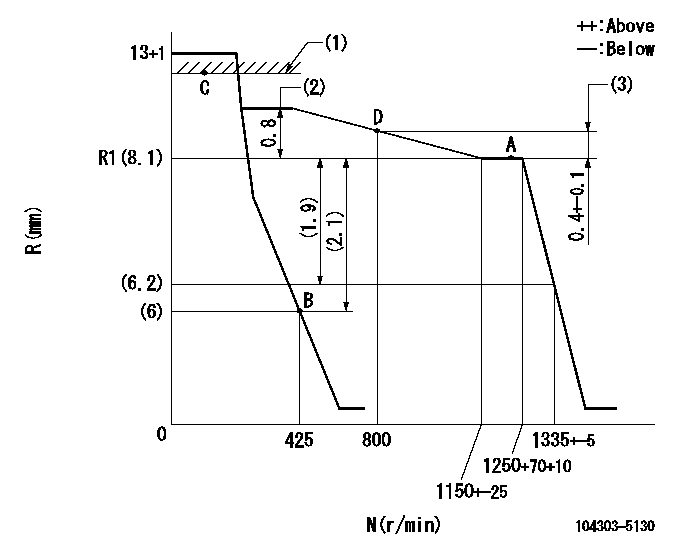
N:Pump speed
R:Rack position (mm)
(1)RACK LIMIT
(2)Torque control stroke
(3)Rack difference between N = N1 and N = N2
----------
N1=1250r/min N2=800r/min
----------
----------
N1=1250r/min N2=800r/min
----------
Speed control lever angle

F:Full speed
I:Idle
(1)Stopper bolt setting
----------
----------
a=12deg+-3deg b=21deg+-6deg
----------
----------
a=12deg+-3deg b=21deg+-6deg
Timing setting

(1)Pump vertical direction
(2)Position of gear mark '00' at No 1 cylinder's beginning of injection
(3)B.T.D.C.: aa
(4)-
----------
aa=18deg
----------
a=(110deg)
----------
aa=18deg
----------
a=(110deg)
Information:
1. Remove the plug from location (1). Install Tool (A) in the hole with the square end down. Move the governor control to the "ON" position until the rack stops against Tool (A). The racks are now in center (zero) position. 2. Disconnect lines (2) from the fuel injection pumps. Remove washers (3). Put caps on all fuel openings.3. Remove bushing (4) with Tool (B).
When injection pumps, spacers and lifters are removed from the injection pump housing, keep the parts of each pump together so they can be installed back in their original location.
4. Remove fuel injection pump with Tool (C).
Be careful when the injection pumps are disassembled. Do not cause damage to the surface on the plunger. The plunger and barrel for each pump are made as a set. Do not put the plunger of one pump in the barrel of another pump. If one part has wear install a complete new pump assembly. Be careful when the plunger is put into the bore of the barrel.
5. Disassemble the fuel injection pump. Remove ring (6). Make a separation of bonnet (5) from the plunger and barrel assembly (7).
Do not remove the gear from the plunger. The gear and plunger are assembled and adjusted at the factory.
6. Remove the plunger and gear segment, washer and spring from the barrel.7. Remove the ring, spring, collar and valve from the barrel. 8. Remove spacer (8) from the pump bore.Install Fuel Injection Pumps
Make sure the fuel racks are in the center (zero) position before the fuel injection pumps are installed. 1. Put plunger (10), washer (5) and spring (9) in position on barrel (4). Put check valve assembly (7), spring (3) and collar (8) in position in bonnet (6). Connect bonnet (6) and barrel (4) together with ring (2). Keep seal (1) with bonnet for use at installation. 2. Put spacer (13) into position in the pump housing bore. Make sure the correct spacer is with each pump.3. Put the space in gear segment (11) in alignment with the groove in barrel (4). 4. Put the injection pump straight down into the housing bore so the space in gear segment (11) is in alignment with pin (12) and the groove in barrel (4) is in alignment with dowel (14). Use Tool (C) to install the pump. 5. Install the seal and bushing (15) in the pump housing bore. If the pump is in the correct position, bushing (15) will turn into the threads of the pump housing with the fingers until it is even with the housing. Tighten bushing (15) to a torque of 205 14 Nm (150 10 lb ft) with Tool (B).6. Install washers (16).7. Connect the fuel lines to the injection pumps and tighten fuel line nuts to a torque of 40 7 Nm (30 5 lb ft) with Tool (D).8. Check for correct installation of the injection pumps with the engine stopped. See the topic "Installation of Injection Pump" in the Systems