Information injection-pump assembly
ZEXEL
104303-5120
1043035120
ISEKI
62156000340A
62156000340a

Rating:
Service parts 104303-5120 INJECTION-PUMP ASSEMBLY:
1.
_
3.
GOVERNOR
4.
SUPPLY PUMP
5.
AUTOM. ADVANCE MECHANIS
6.
COUPLING PLATE
7.
COUPLING PLATE
8.
_
9.
_
11.
Nozzle and Holder
6215300-0022
12.
Open Pre:MPa(Kqf/cm2)
20.6{210}
15.
NOZZLE SET
Include in #1:
104303-5120
as INJECTION-PUMP ASSEMBLY
Cross reference number
ZEXEL
104303-5120
1043035120
ISEKI
62156000340A
62156000340a
Zexel num
Bosch num
Firm num
Name
Calibration Data:
Adjustment conditions
Test oil
1404 Test oil ISO4113 or {SAEJ967d}
1404 Test oil ISO4113 or {SAEJ967d}
Test oil temperature
degC
40
40
45
Nozzle and nozzle holder
105780-8140
Bosch type code
EF8511/9A
Nozzle
105780-0000
Bosch type code
DN12SD12T
Nozzle holder
105780-2080
Bosch type code
EF8511/9
Opening pressure
MPa
17.2
Opening pressure
kgf/cm2
175
Injection pipe
Outer diameter - inner diameter - length (mm) mm 6-2-600
Outer diameter - inner diameter - length (mm) mm 6-2-600
Tester oil delivery pressure
kPa
157
157
157
Tester oil delivery pressure
kgf/cm2
1.6
1.6
1.6
Direction of rotation (viewed from drive side)
Right R
Right R
Injection timing adjustment
Direction of rotation (viewed from drive side)
Right R
Right R
Injection order
1-3-2
Pre-stroke
mm
2.8
2.75
2.85
Beginning of injection position
Drive side NO.1
Drive side NO.1
Difference between angles 1
Cal 1-3 deg. 120 119.5 120.5
Cal 1-3 deg. 120 119.5 120.5
Difference between angles 2
Cyl.1-2 deg. 240 239.5 240.5
Cyl.1-2 deg. 240 239.5 240.5
Injection quantity adjustment
Adjusting point
A
Rack position
8.3
Pump speed
r/min
1250
1250
1250
Average injection quantity
mm3/st.
35
34
36
Max. variation between cylinders
%
0
-2.5
2.5
Basic
*
Fixing the lever
*
Injection quantity adjustment_02
Adjusting point
-
Rack position
6.4+-0.5
Pump speed
r/min
425
425
425
Average injection quantity
mm3/st.
6.6
5.6
7.6
Max. variation between cylinders
%
0
-14
14
Fixing the lever
*
Remarks
Adjust only variation between cylinders; adjust governor according to governor specifications.
Adjust only variation between cylinders; adjust governor according to governor specifications.
Injection quantity adjustment_03
Adjusting point
C
Rack position
11+-0.5
Pump speed
r/min
100
100
100
Average injection quantity
mm3/st.
49
45
53
Fixing the lever
*
Rack limit
*
Test data Ex:
Governor adjustment
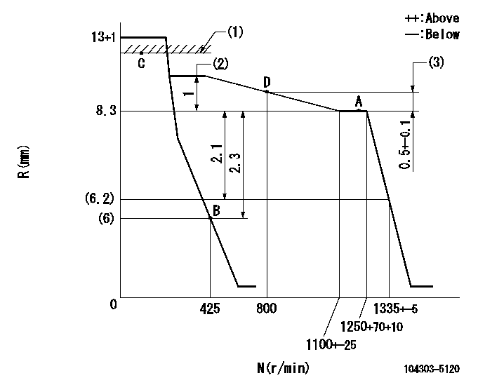
N:Pump speed
R:Rack position (mm)
(1)RACK LIMIT
(2)Torque control stroke
(3)Rack difference between N = N1 and N = N2
----------
N1=1250r/min N2=800r/min
----------
----------
N1=1250r/min N2=800r/min
----------
Speed control lever angle

F:Full speed
I:Idle
(1)Stopper bolt setting
----------
----------
a=12deg+-3deg b=21deg+-6deg
----------
----------
a=12deg+-3deg b=21deg+-6deg
Timing setting

(1)Pump vertical direction
(2)Position of gear mark '00' at No 1 cylinder's beginning of injection
(3)B.T.D.C.: aa
(4)-
----------
aa=18deg
----------
a=(110deg)
----------
aa=18deg
----------
a=(110deg)
Information:
1. Disconnect fuel lines (1) from fuel transfer pump (3). Remove bolts (2). Remove fuel transfer pump (3). Remove gasket from fuel transfer pump.2. Install a new gasket on fuel transfer pump (3). Install fuel transfer pump on rear plate with the bolts (2) that hold it. Connect fuel lines (1) to the fuel transfer pump.Disassemble Fuel Transfer Pump
Start By:a. remove fuel transfer pump 1. Remove tachometer drive (3) from transfer pump cover (4).2. Remove bolts (1). Make a separation between cover (4) and pump body (2). 3. Remove lip-type seal (6) from the cover. Remove plug (5), seal, spring and plunger (bypass valve) from the cover. 4. Remove nut (10) from shaft (7). Remove gear (9) and key (11).5. Remove shaft (7) and gear (8) as a unit. Remove gear (8) from drive shaft (7) with a press.6. Remove idler gear (12). 7. Remove bushing (14), two lip-type seals and the bottom bearing from pump body (1).8. Remove check valve (13). Assemble Fuel Transfer Pump
1. Install bushing (4) in body (3) with Tooling (B). The bushing must not be extended above the (gear) surface of the body.2. Install the check valve in the body with Tooling (A).3. Install lip-type seal (5) with Tooling (C). Install the seal until it is 24.6 0.5 mm (97 .02) from the bottom surface of body (3) and with the lip toward bushing (4) as shown.4. Install lip-type seal (6) with Tooling (D). Install the seal until it is 14.2 0.5 mm (.56 .02 in) from the bottom surface of body (3) and with the lip away from seal (5) as shown.5. Install bearing (7) in body (3) with Tooling (E). The bearing must be even with the surface of the pump body. 6. Heat gear (8) to a maximum temperature of 316°C (600°F). Install gear (8) on shaft (11) until dimension (X) is 49.71 0.25 mm (1.957 0.10 in).7. Install the drive shaft and gear in body (3). Install key, gear (10) and nut (9). Tighten the nut to a torque of 28 7 N m (22 5 lb ft).8. Install idler gear (12) in body (3).9. Install lip-type seal (2) with Tooling (C). Install the seal until it is 3.8 0.5 mm (.15 .02 in) from the top surface of cover (1) with the lip toward the inside as shown. 10. Install plunger (14) (bypass valve), spring (15), seal plug (13) in pump cover (1). Tighten plug (13) to a torque of 28 4 N m (27 3 lb ft).11. Put 7M-7260 Liquid Gasket Material on the surface of cover (1). Install cover (1) on pump body.
Do not let the liquid gasket enter the pump.
The drive shaft must turn freely after the bolts that hold the transfer pump together are tightened.12. Install tachometer drive on transfer pump cover (1).End By:a. install fuel transfer pump