Information injection-pump assembly
ZEXEL
104303-5100
1043035100
ISEKI
62156000213E
62156000213e

Rating:
Service parts 104303-5100 INJECTION-PUMP ASSEMBLY:
1.
_
3.
GOVERNOR
5.
AUTOM. ADVANCE MECHANIS
6.
COUPLING PLATE
7.
COUPLING PLATE
8.
_
9.
_
11.
Nozzle and Holder
6215300-0022
12.
Open Pre:MPa(Kqf/cm2)
20.6{210}
15.
NOZZLE SET
Include in #1:
104303-5100
as INJECTION-PUMP ASSEMBLY
Cross reference number
ZEXEL
104303-5100
1043035100
ISEKI
62156000213E
62156000213e
Zexel num
Bosch num
Firm num
Name
Calibration Data:
Adjustment conditions
Test oil
1404 Test oil ISO4113 or {SAEJ967d}
1404 Test oil ISO4113 or {SAEJ967d}
Test oil temperature
degC
40
40
45
Nozzle and nozzle holder
105780-8140
Bosch type code
EF8511/9A
Nozzle
105780-0000
Bosch type code
DN12SD12T
Nozzle holder
105780-2080
Bosch type code
EF8511/9
Opening pressure
MPa
17.2
Opening pressure
kgf/cm2
175
Injection pipe
Outer diameter - inner diameter - length (mm) mm 6-2-600
Outer diameter - inner diameter - length (mm) mm 6-2-600
Tester oil delivery pressure
kPa
157
157
157
Tester oil delivery pressure
kgf/cm2
1.6
1.6
1.6
Direction of rotation (viewed from drive side)
Right R
Right R
Injection timing adjustment
Direction of rotation (viewed from drive side)
Right R
Right R
Injection order
1-3-2
Pre-stroke
mm
2.8
2.75
2.85
Beginning of injection position
Drive side NO.1
Drive side NO.1
Difference between angles 1
Cal 1-3 deg. 120 119.5 120.5
Cal 1-3 deg. 120 119.5 120.5
Difference between angles 2
Cyl.1-2 deg. 240 239.5 240.5
Cyl.1-2 deg. 240 239.5 240.5
Injection quantity adjustment
Adjusting point
A
Rack position
7.7
Pump speed
r/min
1250
1250
1250
Average injection quantity
mm3/st.
30.5
29.5
31.5
Max. variation between cylinders
%
0
-2.5
2.5
Basic
*
Fixing the lever
*
Injection quantity adjustment_02
Adjusting point
-
Rack position
6.4+-0.5
Pump speed
r/min
425
425
425
Average injection quantity
mm3/st.
6.6
5.6
7.6
Max. variation between cylinders
%
0
-14
14
Fixing the lever
*
Remarks
Adjust only variation between cylinders; adjust governor according to governor specifications.
Adjust only variation between cylinders; adjust governor according to governor specifications.
Injection quantity adjustment_03
Adjusting point
C
Rack position
11+-0.5
Pump speed
r/min
100
100
100
Average injection quantity
mm3/st.
49
45
53
Fixing the lever
*
Rack limit
*
Test data Ex:
Governor adjustment
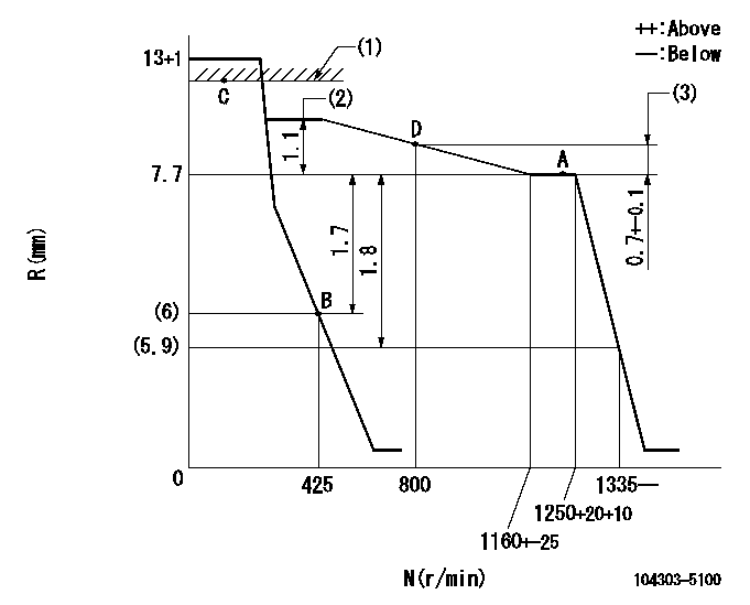
N:Pump speed
R:Rack position (mm)
(1)RACK LIMIT
(2)Torque control stroke
(3)Rack difference between N = N1 and N = N2
----------
N1=1250r/min N2=800r/min
----------
----------
N1=1250r/min N2=800r/min
----------
Speed control lever angle

F:Full speed
I:Idle
(1)Stopper bolt setting
----------
----------
a=12deg+-3deg b=21deg+-6deg
----------
----------
a=12deg+-3deg b=21deg+-6deg
Timing setting

(1)Pump vertical direction
(2)Position of gear mark '00' at No 1 cylinder's beginning of injection
(3)B.T.D.C.: aa
(4)-
----------
aa=18deg
----------
a=(110deg)
----------
aa=18deg
----------
a=(110deg)
Information:
Start By:a. remove vibration damper and pulley 1. Use a punch or Tool (A) to put a hole in seal (1). Use Tool (A) to remove seal (1) from the timing gear cover. When a replacement of the front seal is made, a replacement of the wear sleeve is to be made also. 2. Put Tool (B) in position in the seal bore as shown.3. Install Tool (C) between Tool (B) and the wear sleeve. Turn Tool (C) until the edge of the tool makes a flat place (crease) in the wear sleeve. Do this in two or more places until the wear sleeve is loose.4. Remove Tool (B) and the wear sleeve by hand.Install Crankshaft Front Seal & Wear Sleeve
The wear sleeve and seal must be installed at the same time.1. Install the crankshaft front seal and wear sleeve with Tool (A) as follows: a. Clean and make a preparation of the wear sleeve inside diameter and crankshaft outside diameter with 6V-1541 Quick Cure Primer. Make an application of 9S-3265 Retaining Compound to crankshaft outside diameter and wear sleeve inside diameter before the wear sleeve is installed on the crankshaft.b. Install locator (1) and the bolts on the front of the crankshaft.c. The wear sleeve and seal come as a set with the seal already installed on the wear sleeve. Make sure the lip of the seal is toward the inside of the engine as shown and the outside diameter bevel of the wear sleeve is toward the outside of the engine.d. Put the wear sleeve and seal in position on locator (1). e. Put installer (2) in position on locator (1).f. Put clean engine oil on the face of nut (3) and its contact area on installer (2). Install nut (3) on stud of locator (1).g. Tighten nut (3) until the inside surface of installer (2) comes in contact with locator (1).h. Remove Tool (A) and check the wear sleeve and seal for correct installation.End By:a. install vibration damper and pulley
The wear sleeve and seal must be installed at the same time.1. Install the crankshaft front seal and wear sleeve with Tool (A) as follows: a. Clean and make a preparation of the wear sleeve inside diameter and crankshaft outside diameter with 6V-1541 Quick Cure Primer. Make an application of 9S-3265 Retaining Compound to crankshaft outside diameter and wear sleeve inside diameter before the wear sleeve is installed on the crankshaft.b. Install locator (1) and the bolts on the front of the crankshaft.c. The wear sleeve and seal come as a set with the seal already installed on the wear sleeve. Make sure the lip of the seal is toward the inside of the engine as shown and the outside diameter bevel of the wear sleeve is toward the outside of the engine.d. Put the wear sleeve and seal in position on locator (1). e. Put installer (2) in position on locator (1).f. Put clean engine oil on the face of nut (3) and its contact area on installer (2). Install nut (3) on stud of locator (1).g. Tighten nut (3) until the inside surface of installer (2) comes in contact with locator (1).h. Remove Tool (A) and check the wear sleeve and seal for correct installation.End By:a. install vibration damper and pulley