Information injection-pump assembly
BOSCH
9 400 616 479
9400616479
ZEXEL
104303-3560
1043033560
ISEKI
62156000970B
62156000970b
Rating:
Service parts 104303-3560 INJECTION-PUMP ASSEMBLY:
1.
_
3.
GOVERNOR
4.
SUPPLY PUMP
5.
AUTOM. ADVANCE MECHANIS
6.
COUPLING PLATE
7.
COUPLING PLATE
8.
_
9.
_
11.
Nozzle and Holder
12.
Open Pre:MPa(Kqf/cm2)
11.8{120}

15.
NOZZLE SET
Include in #1:
104303-3560
as INJECTION-PUMP ASSEMBLY
Cross reference number
BOSCH
9 400 616 479
9400616479
ZEXEL
104303-3560
1043033560
ISEKI
62156000970B
62156000970b
Zexel num
Bosch num
Firm num
Name
104303-3560
9 400 616 479
62156000970B ISEKI
INJECTION-PUMP ASSEMBLY
E3AD1 * K 14BV INJECTION PUMP ASSY PES3K PE
E3AD1 * K 14BV INJECTION PUMP ASSY PES3K PE
Calibration Data:
Adjustment conditions
Test oil
1404 Test oil ISO4113 or {SAEJ967d}
1404 Test oil ISO4113 or {SAEJ967d}
Test oil temperature
degC
40
40
45
Nozzle and nozzle holder
105780-8140
Bosch type code
EF8511/9A
Nozzle
105780-0000
Bosch type code
DN12SD12T
Nozzle holder
105780-2080
Bosch type code
EF8511/9
Opening pressure
MPa
17.2
Opening pressure
kgf/cm2
175
Injection pipe
Outer diameter - inner diameter - length (mm) mm 6-2-600
Outer diameter - inner diameter - length (mm) mm 6-2-600
Tester oil delivery pressure
kPa
157
157
157
Tester oil delivery pressure
kgf/cm2
1.6
1.6
1.6
Direction of rotation (viewed from drive side)
Right R
Right R
Injection timing adjustment
Direction of rotation (viewed from drive side)
Right R
Right R
Injection order
1-3-2
Pre-stroke
mm
2.1
2.05
2.15
Beginning of injection position
Drive side NO.1
Drive side NO.1
Difference between angles 1
Cal 1-3 deg. 120 119.5 120.5
Cal 1-3 deg. 120 119.5 120.5
Difference between angles 2
Cyl.1-2 deg. 240 239.5 240.5
Cyl.1-2 deg. 240 239.5 240.5
Injection quantity adjustment
Adjusting point
A
Rack position
9.2
Pump speed
r/min
1300
1300
1300
Average injection quantity
mm3/st.
38
37
39
Max. variation between cylinders
%
0
-2.5
2.5
Basic
*
Fixing the lever
*
Injection quantity adjustment_02
Adjusting point
-
Rack position
6.4+-0.5
Pump speed
r/min
425
425
425
Average injection quantity
mm3/st.
6.5
5.5
7.5
Max. variation between cylinders
%
0
-14
14
Fixing the lever
*
Remarks
Adjust only variation between cylinders; adjust governor according to governor specifications.
Adjust only variation between cylinders; adjust governor according to governor specifications.
Injection quantity adjustment_03
Adjusting point
C
Rack position
13+1
Pump speed
r/min
100
100
100
Average injection quantity
mm3/st.
40
40
Fixing the lever
*
Test data Ex:
Governor adjustment
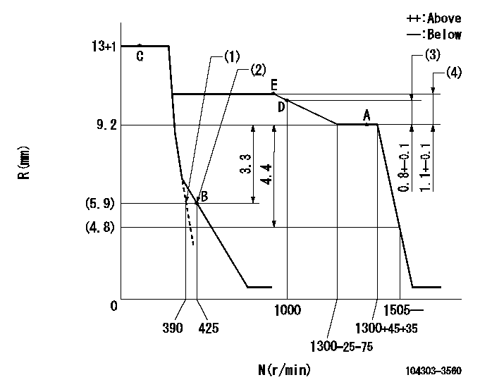
N:Pump speed
R:Rack position (mm)
(1)Set the idle spring.
(2)Main spring setting
(3)Rack difference between N = N1 and N = N2
(4)Rack difference between N = N3 and N = N4
----------
N1=1300r/min N2=1000r/min N3=1300r/min N4=700r/min
----------
----------
N1=1300r/min N2=1000r/min N3=1300r/min N4=700r/min
----------
Speed control lever angle

F:Full speed
I:Idle
(1)Stopper bolt setting
----------
----------
a=7deg+-3deg b=(32deg)+-6deg
----------
----------
a=7deg+-3deg b=(32deg)+-6deg
Stop lever angle

N:Pump normal
S:Stop the pump.
----------
----------
a=10deg+-1deg b=(38deg)
----------
----------
a=10deg+-1deg b=(38deg)
Timing setting

(1)Pump vertical direction
(2)Position of gear mark '00' at No 1 cylinder's beginning of injection
(3)B.T.D.C.: aa
(4)-
----------
aa=18deg
----------
a=(110deg)
----------
aa=18deg
----------
a=(110deg)
Information:
1. Remove bolts (1) and the washers that hold rocker shaft assembly (2) in position.2. Remove rocker shaft assembly (2). Remove the O-ring seal from the rear rocker arm support bracket.3. Put identification marks on push rods (3) as to their location in the engine. Remove the push rods.Install Rocker Shaft Assembly & Push Rods
1. Install push rods (1). Make sure they are in their original location in the engine and in position in the valve lifters.
Loosen the adjusting screws on the rocker arms. This will prevent a bent valve or push rod during installation of the rocker shaft assembly.
2. Install a new O-ring seal in the rear rocker arm support bracket. Put 2P2506 Thread Lubricant on all of the bolts that hold the rocker shaft assembly in position except for the bolt that goes through the rear rocker arm support bracket.3. Put rocker shaft assembly (2) in position on the engine. Make sure the dowels in the support bracket are in alignment with the dowel holes in the cylinder head. Make sure the rocker arms are engaged with the push rods.4. Install the bolts and washers that hold the rocker shaft assembly in position. Tighten them until they are finger tight.
3304 Engine Sequence
3306 Engine Sequence5. Tighten the bolts that hold the rocker shaft as follows:a. Tighten the bolts in number sequence to a torque of 156 N m (115 lb ft).b. Tighten the bolts in number sequence to a torque of 250 17 N m (185 13 lb ft).c. Tighten the bolts again in number sequence to a torque of 250 17 N m (185 13 lb ft).6. See "Valve Clearance Setting" in Testing & Adjusting. Make an adjustment to the valves so the intake valves have 0.38 mm (.015 in) clearance and the exhaust valves have 0.64 mm (.025 in) clearance. Tighten the locknuts for the adjusting screws to a torque of 29 7 N m (21 5 lb ft).End By:a. install valve cover
Have questions with 104303-3560?
Group cross 104303-3560 ZEXEL
Iseki
104303-3560
9 400 616 479
62156000970B
INJECTION-PUMP ASSEMBLY
E3AD1
E3AD1