Information injection-pump assembly
BOSCH
9 400 616 478
9400616478
ZEXEL
104303-3550
1043033550
ISEKI
62156000960B
62156000960b

Rating:
Service parts 104303-3550 INJECTION-PUMP ASSEMBLY:
1.
_
3.
GOVERNOR
4.
SUPPLY PUMP
5.
AUTOM. ADVANCE MECHANIS
6.
COUPLING PLATE
7.
COUPLING PLATE
8.
_
9.
_
11.
Nozzle and Holder
12.
Open Pre:MPa(Kqf/cm2)
11.8{120}

15.
NOZZLE SET
Include in #1:
104303-3550
as INJECTION-PUMP ASSEMBLY
Cross reference number
BOSCH
9 400 616 478
9400616478
ZEXEL
104303-3550
1043033550
ISEKI
62156000960B
62156000960b
Zexel num
Bosch num
Firm num
Name
104303-3550
9 400 616 478
62156000960B ISEKI
INJECTION-PUMP ASSEMBLY
E3AD1 * K
E3AD1 * K
Calibration Data:
Adjustment conditions
Test oil
1404 Test oil ISO4113 or {SAEJ967d}
1404 Test oil ISO4113 or {SAEJ967d}
Test oil temperature
degC
40
40
45
Nozzle and nozzle holder
105780-8140
Bosch type code
EF8511/9A
Nozzle
105780-0000
Bosch type code
DN12SD12T
Nozzle holder
105780-2080
Bosch type code
EF8511/9
Opening pressure
MPa
17.2
Opening pressure
kgf/cm2
175
Injection pipe
Outer diameter - inner diameter - length (mm) mm 6-2-600
Outer diameter - inner diameter - length (mm) mm 6-2-600
Tester oil delivery pressure
kPa
157
157
157
Tester oil delivery pressure
kgf/cm2
1.6
1.6
1.6
Direction of rotation (viewed from drive side)
Right R
Right R
Injection timing adjustment
Direction of rotation (viewed from drive side)
Right R
Right R
Injection order
1-3-2
Pre-stroke
mm
2.1
2.05
2.15
Beginning of injection position
Drive side NO.1
Drive side NO.1
Difference between angles 1
Cal 1-3 deg. 120 119.5 120.5
Cal 1-3 deg. 120 119.5 120.5
Difference between angles 2
Cyl.1-2 deg. 240 239.5 240.5
Cyl.1-2 deg. 240 239.5 240.5
Injection quantity adjustment
Adjusting point
A
Rack position
9.5
Pump speed
r/min
1300
1300
1300
Average injection quantity
mm3/st.
39.2
38.2
40.2
Max. variation between cylinders
%
0
-2.5
2.5
Basic
*
Fixing the lever
*
Injection quantity adjustment_02
Adjusting point
-
Rack position
6.4+-0.5
Pump speed
r/min
425
425
425
Average injection quantity
mm3/st.
6.5
5.5
7.5
Max. variation between cylinders
%
0
-14
14
Fixing the lever
*
Remarks
Adjust only variation between cylinders; adjust governor according to governor specifications.
Adjust only variation between cylinders; adjust governor according to governor specifications.
Injection quantity adjustment_03
Adjusting point
C
Rack position
13+1
Pump speed
r/min
100
100
100
Average injection quantity
mm3/st.
40
40
Fixing the lever
*
Test data Ex:
Governor adjustment
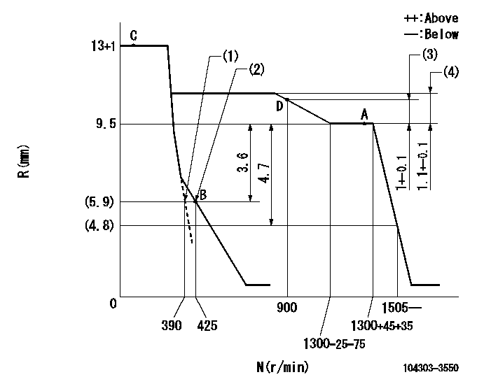
N:Pump speed
R:Rack position (mm)
(1)Set the idle spring.
(2)Main spring setting
(3)Rack difference between N = N1 and N = N2
(4)Rack difference between N = N3 and N = N4
----------
N1=1300r/min N2=900r/min N3=1300r/min N4=800r/min
----------
----------
N1=1300r/min N2=900r/min N3=1300r/min N4=800r/min
----------
Speed control lever angle

F:Full speed
I:Idle
(1)Stopper bolt setting
----------
----------
a=7deg+-3deg b=(32deg)+-6deg
----------
----------
a=7deg+-3deg b=(32deg)+-6deg
Stop lever angle

N:Pump normal
S:Stop the pump.
----------
----------
a=10deg+-1deg b=(38deg)
----------
----------
a=10deg+-1deg b=(38deg)
Timing setting

(1)Pump vertical direction
(2)Position of gear mark '00' at No 1 cylinder's beginning of injection
(3)B.T.D.C.: aa
(4)-
----------
aa=18deg
----------
a=(110deg)
----------
aa=18deg
----------
a=(110deg)
Information:
2. Remove pipe (1) and the gasket between aftercooler cover (2) and the turbocharger. If necessary, remove the O-ring seals from the pipe.3. Remove the bolts and clamps that hold tube assemblies (3) to each end of the aftercooler. Remove tube assemblies (3) from each end of the aftercooler. If necessary, remove the O-ring seals from the tube assemblies. An O-ring seal on each end of the aftercooler core holds the adapters in position.4. Remove adapters (4) and the gaskets from each end of the aftercooler.5. Remove all bolts (5) that hold aftercooler cover (2) in position. Remove the aftercooler cover and gasket from the engine. 6. Remove aftercooler core (6) and the gasket from the engine. If necessary, remove the O-ring seals from the aftercooler core. Two of the bolts that hold the aftercooler housing in position are on the inside of the aftercooler housing.7. Remove the bolts and spacers that hold aftercooler housing (7) to the engine. Make a note of the location of the spacers. Remove the aftercooler housing and gaskets from the engine.Install Aftercooler
Inspect all O-ring seals and gaskets, and make replacements if necessary. 1. Put the gaskets and aftercooler housing (1) in position on the engine. Install the bolts and spacers that hold the aftercooler housing.2. Install the O-ring seals on the aftercooler core, and put a thin layer of clean engine oil on them. Put the gasket and aftercooler core (2) in position on the engine. 3. Put the gasket and aftercooler cover (3) in position. Install the bolts that hold the aftercooler cover. Force may be required to push the adapters around the O-ring seals on the aftercooler core. Make sure the O-ring seals stay in position on the aftercooler core.4. Put a thin layer of clean engine oil in the bores of adapters (4). Install a gasket and adapter on each end of the aftercooler core. 5. Install the O-ring seals on tube assemblies (5), and put a thin layer of clean engine oil on them. Put the tube assemblies in position on each end of the aftercooler, and install the bolts and clamps that hold them.6. Install the O-ring seals on pipe (6), and put a thin layer of clean engine oil on them. Put the pipe and gasket in position between the aftercooler and the turbocharger. Install the bolts that hold it.7. Fill the radiator with coolant to the correct level. See the Operation & Maintenance Manual.
Inspect all O-ring seals and gaskets, and make replacements if necessary. 1. Put the gaskets and aftercooler housing (1) in position on the engine. Install the bolts and spacers that hold the aftercooler housing.2. Install the O-ring seals on the aftercooler core, and put a thin layer of clean engine oil on them. Put the gasket and aftercooler core (2) in position on the engine. 3. Put the gasket and aftercooler cover (3) in position. Install the bolts that hold the aftercooler cover. Force may be required to push the adapters around the O-ring seals on the aftercooler core. Make sure the O-ring seals stay in position on the aftercooler core.4. Put a thin layer of clean engine oil in the bores of adapters (4). Install a gasket and adapter on each end of the aftercooler core. 5. Install the O-ring seals on tube assemblies (5), and put a thin layer of clean engine oil on them. Put the tube assemblies in position on each end of the aftercooler, and install the bolts and clamps that hold them.6. Install the O-ring seals on pipe (6), and put a thin layer of clean engine oil on them. Put the pipe and gasket in position between the aftercooler and the turbocharger. Install the bolts that hold it.7. Fill the radiator with coolant to the correct level. See the Operation & Maintenance Manual.
Have questions with 104303-3550?
Group cross 104303-3550 ZEXEL
Iseki
104303-3550
9 400 616 478
62156000960B
INJECTION-PUMP ASSEMBLY
E3AD1
E3AD1