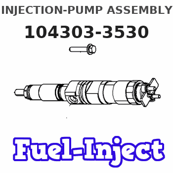
Information injection-pump assembly
BOSCH
9 400 616 476
9400616476
ZEXEL
104303-3530
1043033530
ISEKI
62156000860
62156000860
Rating:
Service parts 104303-3530 INJECTION-PUMP ASSEMBLY:
1.
_
3.
GOVERNOR
4.
SUPPLY PUMP
5.
AUTOM. ADVANCE MECHANIS
6.
COUPLING PLATE
7.
COUPLING PLATE
8.
_
9.
_
11.
Nozzle and Holder
12.
Open Pre:MPa(Kqf/cm2)
11.8{120}

15.
NOZZLE SET
Include in #1:
104303-3530
as INJECTION-PUMP ASSEMBLY
Cross reference number
BOSCH
9 400 616 476
9400616476
ZEXEL
104303-3530
1043033530
ISEKI
62156000860
62156000860
Zexel num
Bosch num
Firm num
Name
104303-3530
9 400 616 476
62156000860 ISEKI
INJECTION-PUMP ASSEMBLY
E3AD1 * K
E3AD1 * K
Calibration Data:
Adjustment conditions
Test oil
1404 Test oil ISO4113 or {SAEJ967d}
1404 Test oil ISO4113 or {SAEJ967d}
Test oil temperature
degC
40
40
45
Nozzle and nozzle holder
105780-8140
Bosch type code
EF8511/9A
Nozzle
105780-0000
Bosch type code
DN12SD12T
Nozzle holder
105780-2080
Bosch type code
EF8511/9
Opening pressure
MPa
17.2
Opening pressure
kgf/cm2
175
Injection pipe
Outer diameter - inner diameter - length (mm) mm 6-2-600
Outer diameter - inner diameter - length (mm) mm 6-2-600
Tester oil delivery pressure
kPa
157
157
157
Tester oil delivery pressure
kgf/cm2
1.6
1.6
1.6
Direction of rotation (viewed from drive side)
Left L
Left L
Injection timing adjustment
Direction of rotation (viewed from drive side)
Left L
Left L
Injection order
1-3-2
Pre-stroke
mm
2.1
2.05
2.15
Beginning of injection position
Drive side NO.1
Drive side NO.1
Difference between angles 1
Cal 1-3 deg. 120 119.5 120.5
Cal 1-3 deg. 120 119.5 120.5
Difference between angles 2
Cyl.1-2 deg. 240 239.5 240.5
Cyl.1-2 deg. 240 239.5 240.5
Injection quantity adjustment
Adjusting point
A
Rack position
8.1
Pump speed
r/min
1200
1200
1200
Average injection quantity
mm3/st.
33.2
32.2
34.2
Max. variation between cylinders
%
0
-2.5
2.5
Basic
*
Fixing the lever
*
Injection quantity adjustment_02
Adjusting point
-
Rack position
5.9+-0.5
Pump speed
r/min
575
575
575
Average injection quantity
mm3/st.
9
8
10
Max. variation between cylinders
%
0
-14
14
Fixing the lever
*
Remarks
Adjust only variation between cylinders; adjust governor according to governor specifications.
Adjust only variation between cylinders; adjust governor according to governor specifications.
Injection quantity adjustment_03
Adjusting point
C
Rack position
13+1
Pump speed
r/min
100
100
100
Average injection quantity
mm3/st.
36
36
Fixing the lever
*
Test data Ex:
Governor adjustment

N:Pump speed
R:Rack position (mm)
(1)Set the idle spring.
(2)Main spring setting
(3)Rack difference from N = N1
(4)Rack difference between N = N2 and N = N3
----------
N1=1200r/min N2=1200r/min N3=400r/min
----------
----------
N1=1200r/min N2=1200r/min N3=400r/min
----------
Speed control lever angle
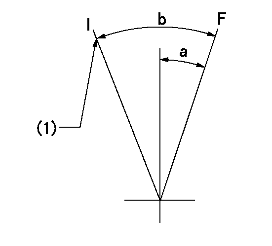
F:Full speed
I:Idle
(1)Stopper bolt setting
----------
----------
a=15deg+-3deg b=24deg+-6deg
----------
----------
a=15deg+-3deg b=24deg+-6deg
Stop lever angle
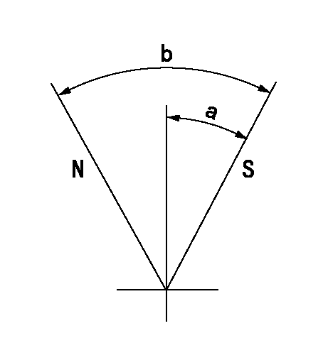
N:Pump normal
S:Stop the pump.
----------
----------
a=10deg+-1deg b=(38deg)
----------
----------
a=10deg+-1deg b=(38deg)
Timing setting

(1)Pump vertical direction
(2)Position of gear mark 'Z' at No 1 cylinder's beginning of injection
(3)B.T.D.C.: aa
(4)-
----------
aa=18deg
----------
a=(120deg)
----------
aa=18deg
----------
a=(120deg)
Information:
3306 Engine Shown1. Turn the fuel supply line valve to the "OFF" position.2. Remove the clamp that holds fuel drain line (1) to the fuel transfer pump. Remove fuel lines (4) and (5).3. Remove bolts (2) and fuel transfer pump (3) from the fuel injection pump housing. Remove the O-ring seal from the fuel transfer pump if necessary.4. Make sure the O-ring seal is in position on the fuel transfer pump. Put the fuel transfer pump in position on the fuel injection pump housing. Install bolts (2) that hold the fuel transfer pump to the fuel injection pump housing.5. Install the clamp that holds fuel drain line (1) to the fuel transfer pump. Install fuel line (4) between the fuel transfer pump and the fuel filter base. Install fuel line (5) between the fuel transfer pump and the fuel priming pump.6. Turn the fuel supply line valve to the "ON" position.Disassemble Fuel Transfer Pump
Start By:a. remove fuel transfer pump
Cover (1) is under spring force. To prevent possible personal injury, carefully remove bolts (2) and cover (1).
1. Remove bolts (2) and cover (1) from the housing. 2. Remove O-ring seals (3) and (4) from the cover.3. Remove valve assembly (5) from the cover. 4. Remove spring (6) from the housing. 5. Remove piston (12) from sleeve (10). Remove washer (15), valve assembly (14) and seal (13) from piston (12).6. Remove sleeve (10) from housing (7). Remove O-ring seal (11) from the sleeve.7. Remove guide and tappet assembly (9) and seal (8) from housing (7). 8. Remove two screws (16), cover (17) and the seal from housing (7). 9. Remove valve assembly (18) from housing (7).Assemble Fuel Transfer Pump
Be sure all parts of the fuel transfer pump are clean before assembly.
1. Install valve assembly (2) in housing (1) as shown. 2. Put clean diesel fuel on seal (2). Put seal (3) in position on cover (4) as shown. Put cover (4) on housing (1). Install the screws that hold the cover. 3. Put clean diesel fuel on seal (5). Put seal (5) and guide and tappet assembly (6) in position in housing (1).4. Put clean diesel fuel on O-ring seal (8). Put O-ring seal (8) in position on sleeve (7). Install sleeve (7) in housing (1).5. Install piston (9) in sleeve (7).6. Put clean diesel fuel on seal (10). Put seal (10), valve assembly (11) and washer (12) in position in piston (7). 7. Put clean diesel fuel on O-ring seals (13) and (14). Put the O-ring seals and valve assembly (15) in position in cover (16) as shown. 8. Put spring (17) and cover (16) in position on housing (1). Install the bolts that hold the spring and cover.End By:a. install fuel transfer pump
Have questions with 104303-3530?
Group cross 104303-3530 ZEXEL
Iseki
104303-3530
9 400 616 476
62156000860
INJECTION-PUMP ASSEMBLY
E3AD1
E3AD1