Information injection-pump assembly
BOSCH
9 400 616 475
9400616475
ZEXEL
104303-3520
1043033520
ISEKI
62156000680A
62156000680a

Rating:
Service parts 104303-3520 INJECTION-PUMP ASSEMBLY:
1.
_
3.
GOVERNOR
4.
SUPPLY PUMP
5.
AUTOM. ADVANCE MECHANIS
6.
COUPLING PLATE
7.
COUPLING PLATE
8.
_
9.
_
11.
Nozzle and Holder
12.
Open Pre:MPa(Kqf/cm2)
11.8{120}

15.
NOZZLE SET
Include in #1:
104303-3520
as INJECTION-PUMP ASSEMBLY
Cross reference number
BOSCH
9 400 616 475
9400616475
ZEXEL
104303-3520
1043033520
ISEKI
62156000680A
62156000680a
Zexel num
Bosch num
Firm num
Name
104303-3520
9 400 616 475
62156000680A ISEKI
INJECTION-PUMP ASSEMBLY
E3AD1 K 14BV INJECTION PUMP ASSY PES3K PE
E3AD1 K 14BV INJECTION PUMP ASSY PES3K PE
Calibration Data:
Adjustment conditions
Test oil
1404 Test oil ISO4113 or {SAEJ967d}
1404 Test oil ISO4113 or {SAEJ967d}
Test oil temperature
degC
40
40
45
Nozzle and nozzle holder
105780-8140
Bosch type code
EF8511/9A
Nozzle
105780-0000
Bosch type code
DN12SD12T
Nozzle holder
105780-2080
Bosch type code
EF8511/9
Opening pressure
MPa
17.2
Opening pressure
kgf/cm2
175
Injection pipe
Outer diameter - inner diameter - length (mm) mm 6-2-600
Outer diameter - inner diameter - length (mm) mm 6-2-600
Tester oil delivery pressure
kPa
157
157
157
Tester oil delivery pressure
kgf/cm2
1.6
1.6
1.6
Direction of rotation (viewed from drive side)
Left L
Left L
Injection timing adjustment
Direction of rotation (viewed from drive side)
Left L
Left L
Injection order
1-3-2
Pre-stroke
mm
2.1
2.05
2.15
Beginning of injection position
Drive side NO.1
Drive side NO.1
Difference between angles 1
Cal 1-3 deg. 120 119.5 120.5
Cal 1-3 deg. 120 119.5 120.5
Difference between angles 2
Cyl.1-2 deg. 240 239.5 240.5
Cyl.1-2 deg. 240 239.5 240.5
Injection quantity adjustment
Adjusting point
A
Rack position
8.8
Pump speed
r/min
1400
1400
1400
Average injection quantity
mm3/st.
39.8
38.8
40.8
Max. variation between cylinders
%
0
-2.5
2.5
Basic
*
Fixing the lever
*
Injection quantity adjustment_02
Adjusting point
-
Rack position
6.1+-0.5
Pump speed
r/min
475
475
475
Average injection quantity
mm3/st.
9
8
10
Max. variation between cylinders
%
0
-14
14
Fixing the lever
*
Remarks
Adjust only variation between cylinders; adjust governor according to governor specifications.
Adjust only variation between cylinders; adjust governor according to governor specifications.
Injection quantity adjustment_03
Adjusting point
C
Rack position
13+1
Pump speed
r/min
100
100
100
Average injection quantity
mm3/st.
36
36
Fixing the lever
*
Test data Ex:
Governor adjustment
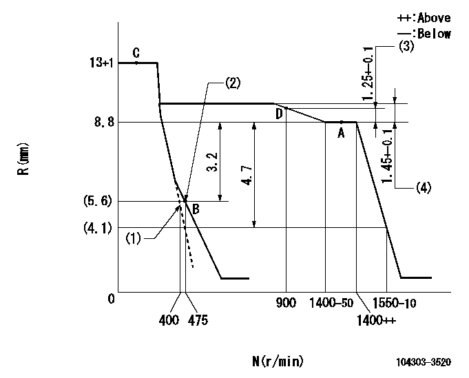
N:Pump speed
R:Rack position (mm)
(1)Set the idle spring.
(2)Main spring setting
(3)Rack difference from N = N1
(4)Rack difference between N = N2 and N = N3
----------
N1=1400r/min N2=1400r/min N3=500r/min
----------
----------
N1=1400r/min N2=1400r/min N3=500r/min
----------
Speed control lever angle
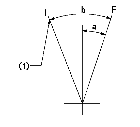
F:Full speed
I:Idle
(1)Stopper bolt setting
----------
----------
a=15deg+-3deg b=28deg+-6deg
----------
----------
a=15deg+-3deg b=28deg+-6deg
Stop lever angle
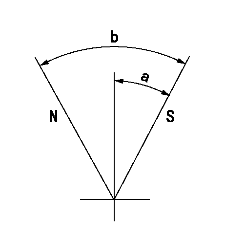
N:Pump normal
S:Stop the pump.
----------
----------
a=10deg+-1deg b=(38deg)
----------
----------
a=10deg+-1deg b=(38deg)
Timing setting

(1)Pump vertical direction
(2)Position of gear mark 'Z' at No 1 cylinder's beginning of injection
(3)B.T.D.C.: aa
(4)-
----------
aa=18deg
----------
a=(120deg)
----------
aa=18deg
----------
a=(120deg)
Information:
Start By:a. disassemble governorb. remove fuel injection pumps 1. Remove cover (1) from the fuel injection pump housing. 2. Remove rack (2) from the fuel injection pump housing.
If the original lifters are to be installed in the fuel injection pump housing, put identification marks on them as to their location in the housing.
3. Remove lifters (3) from the fuel injection pump housing. 4. Put the fuel injection pump housing on end on blocks, and use Tool (A) to remove snap ring (4) from the camshaft. 5. Use a soft hammer to push the camshaft toward the governor end of the fuel injection pump housing to loosen washer (5) on the camshaft. Remove washer (5). 6. Remove camshaft (6) from the fuel injection pump housing. 7. Remove bearings (7) from the drive end of the fuel injection pump housing. 8. Remove bearings (8) from the governor end of the fuel injection pump housing.Assemble Fuel Injection Pump Housing
Be sure all oil passages are clear and put clean engine oil on all parts before assembly.1. Use Tool (A) to install bearing (2) in the governor end of the fuel injection pump housing with joint (3) toward the top of the fuel injection pump housing. Install the bearing so it is 0.25 0.20 mm (.010 0.008 in) below the surface of the housing.2. Use Tool (A) to install bearing (1) in the governor end of the fuel injection pump housing so it is 7.16 0.13 mm (0.282 0.005 in) below the surface of the housing. 3. Use Tool (A) to install bearing (4) in the drive end of the fuel injection pump housing with the joint in the bearing toward the top of the fuel injection pump housing. Install the bearing so it is 1.00 0.25 mm (0.039 0.010 in) below the surface of the housing. 4. Install plate assembly (6) of Tool (C) on the drive end of the fuel injection pump housing to install the bearing for the rack. Use clean grease to hold the new rack bearing on driver (5) of Tool (C). Install the driver and bearing in plate assembly (6) with the groove in the driver in alignment with the pin in the plate. Use a hammer to push the bearing into position. The bearing will be installed to the correct depth when the shoulder of the driver is against plate assembly (6).5. Remove Tool (C) from the fuel injection pump housing. The rack bearing must be installed so it is 0.25 0.25 mm (0.010 0.010 in) below the surface of the housing. 6. Install camshaft (7) in the fuel injection pump housing.7. Put the fuel injection pump housing on end, and put a block under the camshaft. 8. Put washer (9) over the end of the camshaft, and use Tool (A) and a spacer (8) that has an inside diameter of 38.1 mm (1.5 in) and a length of 31.75 mm (1.25 in) to push the washer
Have questions with 104303-3520?
Group cross 104303-3520 ZEXEL
Iseki
104303-3520
9 400 616 475
62156000680A
INJECTION-PUMP ASSEMBLY
E3AD1
E3AD1