Information injection-pump assembly
ZEXEL
104303-3450
1043033450
ISEKI
62156000182D
62156000182d
Rating:
Service parts 104303-3450 INJECTION-PUMP ASSEMBLY:
1.
_
3.
GOVERNOR
5.
AUTOM. ADVANCE MECHANIS
6.
COUPLING PLATE
7.
COUPLING PLATE
8.
_
9.
_
11.
Nozzle and Holder
6515300-1100E
12.
Open Pre:MPa(Kqf/cm2)
11.8{120}

15.
NOZZLE SET
Include in #1:
104303-3450
as INJECTION-PUMP ASSEMBLY
Cross reference number
ZEXEL
104303-3450
1043033450
ISEKI
62156000182D
62156000182d
Zexel num
Bosch num
Firm num
Name
Calibration Data:
Adjustment conditions
Test oil
1404 Test oil ISO4113 or {SAEJ967d}
1404 Test oil ISO4113 or {SAEJ967d}
Test oil temperature
degC
40
40
45
Nozzle and nozzle holder
105780-8140
Bosch type code
EF8511/9A
Nozzle
105780-0000
Bosch type code
DN12SD12T
Nozzle holder
105780-2080
Bosch type code
EF8511/9
Opening pressure
MPa
17.2
Opening pressure
kgf/cm2
175
Injection pipe
Outer diameter - inner diameter - length (mm) mm 6-2-600
Outer diameter - inner diameter - length (mm) mm 6-2-600
Tester oil delivery pressure
kPa
157
157
157
Tester oil delivery pressure
kgf/cm2
1.6
1.6
1.6
Direction of rotation (viewed from drive side)
Left L
Left L
Injection timing adjustment
Direction of rotation (viewed from drive side)
Left L
Left L
Injection order
1-3-2
Pre-stroke
mm
2.1
2.05
2.15
Beginning of injection position
Drive side NO.1
Drive side NO.1
Difference between angles 1
Cal 1-3 deg. 120 119.5 120.5
Cal 1-3 deg. 120 119.5 120.5
Difference between angles 2
Cyl.1-2 deg. 240 239.5 240.5
Cyl.1-2 deg. 240 239.5 240.5
Injection quantity adjustment
Adjusting point
A
Rack position
8.5
Pump speed
r/min
1300
1300
1300
Average injection quantity
mm3/st.
35.6
34.6
36.6
Max. variation between cylinders
%
0
-2.5
2.5
Basic
*
Fixing the lever
*
Injection quantity adjustment_02
Adjusting point
-
Rack position
5.9+-0.5
Pump speed
r/min
575
575
575
Average injection quantity
mm3/st.
9
8
10
Max. variation between cylinders
%
0
-14
14
Fixing the lever
*
Remarks
Adjust only variation between cylinders; adjust governor according to governor specifications.
Adjust only variation between cylinders; adjust governor according to governor specifications.
Injection quantity adjustment_03
Adjusting point
C
Rack position
13+1
Pump speed
r/min
100
100
100
Average injection quantity
mm3/st.
36
36
Fixing the lever
*
Test data Ex:
Governor adjustment
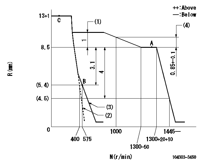
N:Pump speed
R:Rack position (mm)
(1)Torque control stroke
(2)Set the idle spring.
(3)Main spring setting
(4)Rack difference between N = N1 and N = N2
----------
N1=1300r/min N2=1000r/min
----------
----------
N1=1300r/min N2=1000r/min
----------
Speed control lever angle
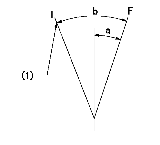
F:Full speed
I:Idle
(1)Stopper bolt setting
----------
----------
a=15deg+-3deg b=31deg+-6deg
----------
----------
a=15deg+-3deg b=31deg+-6deg
Stop lever angle
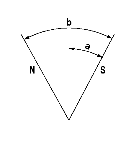
N:Pump normal
S:Stop the pump.
----------
----------
a=10deg+-1deg b=(38deg)
----------
----------
a=10deg+-1deg b=(38deg)
Timing setting

(1)Pump vertical direction
(2)Position of gear mark 'Z' at No 1 cylinder's beginning of injection
(3)B.T.D.C.: aa
(4)-
----------
aa=18deg
----------
a=(120deg)
----------
aa=18deg
----------
a=(120deg)
Information:
Start By:a. remove timing gear coverb. remove fuel injection pump housing and governor 1. Remove four bolts (2), plate (3) and idler gear (1). 2. If the camshaft is not going to be removed, use Tool (A) to remove camshaft gear (4).
Do not turn the crankshaft with the camshaft gear removed. Damage can be caused to the pistons and valves or both.
3. Remove bolts (5) that hold timing gear plate (6) to the cylinder block.4. Remove timing gear plate (6). 5. Use Tool (B) to remove the bearing from the idler gear. The following steps are for the installation of the timing gears and plate.6. Install a new gasket on the timing gear plate.7. Put timing gear plate (6) in position on the cylinder block and install the bolts that hold the timing gear plate to the cylinder block.8. Heat camshaft gear (4) to a maximum temperature of 205° C (400° F) for no longer than three hours and install it on the camshaft.9. Use Tool (B) and install the bearing in the idler gear. Set the gear on the front face (face with the timing marks). Drive the bearing from the rear face toward the front face of the gear. Install the bearing to a depth of 1.5 0.5 mm (.06 .02 in) below the rear face of the idler gear.10. Install the idler gear, plate and bolts. Be sure No. 1 cylinder is at top center on the compression stroke. Install the idler gear so "V" mark (7) on the idler gear is in alignment with the "V" mark on the crankshaft gear. "K" marks (8) on the camshaft gear can be seen at the outer edges of the idler gear.End By:a. install fuel injection pump housing and governorb. install timing gear cover