Information injection-pump assembly
BOSCH
9 400 616 438
9400616438
ZEXEL
104303-2500
1043032500
ISHIKAWAJIMA-S
131017030
131017030
Rating:
Service parts 104303-2500 INJECTION-PUMP ASSEMBLY:
1.
_
3.
GOVERNOR
5.
AUTOM. ADVANCE MECHANIS
6.
COUPLING PLATE
7.
COUPLING PLATE
8.
_
9.
_
11.
Nozzle and Holder
13140 61 32
12.
Open Pre:MPa(Kqf/cm2)
11.8{120}

15.
NOZZLE SET
Include in #1:
104303-2500
as INJECTION-PUMP ASSEMBLY
Cross reference number
BOSCH
9 400 616 438
9400616438
ZEXEL
104303-2500
1043032500
ISHIKAWAJIMA-S
131017030
131017030
Zexel num
Bosch num
Firm num
Name
104303-2500
9 400 616 438
131017030 ISHIKAWAJIMA-S
INJECTION-PUMP ASSEMBLY
H843 * K 14BV PES3K PE
H843 * K 14BV PES3K PE
Calibration Data:
Adjustment conditions
Test oil
1404 Test oil ISO4113 or {SAEJ967d}
1404 Test oil ISO4113 or {SAEJ967d}
Test oil temperature
degC
40
40
45
Nozzle and nozzle holder
105780-8140
Bosch type code
EF8511/9A
Nozzle
105780-0000
Bosch type code
DN12SD12T
Nozzle holder
105780-2080
Bosch type code
EF8511/9
Opening pressure
MPa
17.2
Opening pressure
kgf/cm2
175
Injection pipe
Outer diameter - inner diameter - length (mm) mm 6-2-600
Outer diameter - inner diameter - length (mm) mm 6-2-600
Tester oil delivery pressure
kPa
157
157
157
Tester oil delivery pressure
kgf/cm2
1.6
1.6
1.6
Direction of rotation (viewed from drive side)
Right R
Right R
Injection timing adjustment
Direction of rotation (viewed from drive side)
Right R
Right R
Injection order
1-2-3
Pre-stroke
mm
1.95
1.9
2
Beginning of injection position
Drive side NO.1
Drive side NO.1
Difference between angles 1
Cyl.1-2 deg. 120 119.5 120.5
Cyl.1-2 deg. 120 119.5 120.5
Difference between angles 2
Cal 1-3 deg. 240 239.5 240.5
Cal 1-3 deg. 240 239.5 240.5
Injection quantity adjustment
Adjusting point
A
Rack position
7.8
Pump speed
r/min
750
750
750
Average injection quantity
mm3/st.
27.8
26.8
28.8
Max. variation between cylinders
%
0
-3
3
Basic
*
Fixing the lever
*
Injection quantity adjustment_02
Adjusting point
B
Rack position
7.4
Pump speed
r/min
1350
1350
1350
Average injection quantity
mm3/st.
29.8
25.8
33.8
Max. variation between cylinders
%
0
-4
4
Fixing the lever
*
Injection quantity adjustment_03
Adjusting point
C
Rack position
4.5+-0.5
Pump speed
r/min
375
375
375
Average injection quantity
mm3/st.
8.5
7.5
9.5
Max. variation between cylinders
%
0
-14
14
Fixing the lever
*
Remarks
Adjust only variation between cylinders; adjust governor according to governor specifications.
Adjust only variation between cylinders; adjust governor according to governor specifications.
Injection quantity adjustment_04
Adjusting point
D
Rack position
13+1
Pump speed
r/min
100
100
100
Average injection quantity
mm3/st.
45
45
Fixing the lever
*
Test data Ex:
Governor adjustment
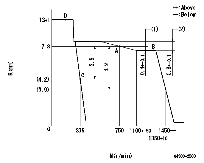
N:Pump speed
R:Rack position (mm)
(1)Rack difference between N = N1 and N = N2
(2)Rack difference between N = N3 and N = N4
----------
N1=1350r/min N2=750r/min N3=1350r/min N4=500r/min
----------
----------
N1=1350r/min N2=750r/min N3=1350r/min N4=500r/min
----------
Speed control lever angle
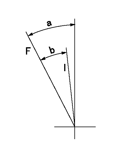
F:Full speed
I:Idle
----------
----------
a=39deg+-3deg b=37deg+-6deg
----------
----------
a=39deg+-3deg b=37deg+-6deg
Stop lever angle

N:Pump normal
S:Stop the pump.
----------
----------
a=(0deg) b=(38deg)
----------
----------
a=(0deg) b=(38deg)
Timing setting

(1)Pump vertical direction
(2)Pump's key groove position at No. 1 cylinder's beginning of injection.
(3)-
(4)-
----------
----------
a=(40deg)
----------
----------
a=(40deg)
Information:
Governor Linkage Adjustment
(1) Rod. (2) Nut. (3) Control lever. (4) Lever. (5) Pin. (6) High idle stop. (7) Locknut. (8) Low idle stop. (9) Locknut. (10) Decelerator treadle. (11) Floor plate. (12) Accelerator treadle. (13) Lever. (14) Rod. (15) Locknut. (16) Lever. (17) Locknut. (A) 9.7 mm (.38 in). (B) 4.8 mm (.19 in). (C) 38.1 mm (1.50 in). (D) 60.5 3.0 mm (2.38 .12 in). DO NOT USE control lever (3), or decelerator treadle (10) to shut OFF the engine.To shut engine OFF, pull up on accelerator treadle (12).1. Tighten nut (2) just enough so position of control lever (3) is not affected by the operation of the accelerator treadle (12) and decelerator treadle (10).2. With the parking brake ON and engine stopped, BE SURE disconnect switch is OFF.3. Remove pin (5).4. Loosen LOW IDLE stop (8) and HIGH IDLE stop (6) so they do not touch lever (13).5. Move control lever (3) to LOW IDLE position.6. Turn LOW IDLE stop (8) until it touches lever (13) and tighten locknut (9).7. Adjust length of rod (14) so distance from top of lever (16) to bottom of floor plate (11) is (C) 38.1 mm (1.50 in) as shown.8. Loosen locknut (15) and adjust length of rod so top of decelerator treadle (10) is (B) 4.8 mm (.19 in) above floor plate (11) as shown. If machine is equipped with a thick floor insulation pad, (used with enclosed cab), adjust decelerator treadle (10) so top of treadle is (A) 9.7 mm (.38 in) above top of floor plate and tighten locknut (15).9. Move control lever (3) to HIGH IDLE position.10. Turn HIGH IDLE stop (6) until it touches lever (13) and tighten locknut (7).11. Loosen locknut (17) and adjust accelerator treadle (12) so that distance from bottom of plate on treadle to top of floor plate (11) is (D) 60.5 3.0 mm (2.38 .12 in) as shown.12. Move lever (4) to HIGH IDLE position and adjust length of rod (1) so pin (5) can be installed.13. Install pin (5).
DO NOT adjust the linkage so the treadle can be used to shut off the engine. If the operator is in a standing position and places a foot on the treadle, the engine could be unexpectedly shut off, creating a situation where the machine can be difficult to control.
518 Skidder
1. Move governor shaft (3) to SHUT OFF position and install lever (2) on shaft (3) at angle (A).2. Adjust length of rod (5) so stop (4) on pedal (1) is at dimension (B) from the floor plate.Angle (A) ... 35 5°Dimension (B) ... 67 1 mm (2.64 .01 in)3. Tighten nut (6) ... 12 4 N m (9 3 lb ft)D5H
1. Move governor lever (2) to high idle and install spring (6). Move governor lever (2) to vertical position and adjust stop bolt (3) to contact lever (2), back off one turn and lock.2. Position lever (9) on the splined governor shaft
Have questions with 104303-2500?
Group cross 104303-2500 ZEXEL
Ishikawajima-S
104303-2500
9 400 616 438
131017030
INJECTION-PUMP ASSEMBLY
H843
H843